By: Natalie Arevalo (Design & Manufacturing Engineer)
Approved By: Lucas Gutierrez (Project Manager)
Discussion
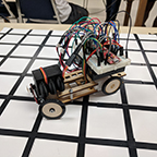
Various modifications were done to the original chassis to be able to complete the mission proposed the customer. Major modifications were done to the wooden chassis to make it compatible with the 5.03 3DoT board. Openings on the top part of the chassis were made so that all of the ports and headers could be accessed. In addition, another opening was made to be able to place the battery into the 3DoT board. Furthermore, an opening in between the GM6 motor placing was made to have the wires of the motors and their encoders be brought up and over the top part of the chassis to plug into the board. Another piece was cut out of the top part of the chassis to allow for the servo to be able to be raised and lowered as it was connected to the front axle. Additionally, six 3mm holes were strategically placed in which dawls would be later glued into. Three of these holes and the respective dawls were set aside for an anchoring point for the servo holder. The other three holes and their dawls were used to hold up 1.5×1.5 in platform to become a phone holder. Two more 5mm holes were also placed in the back to become zip tie holders to keep wires secured. Finally, openings were made for the motor encoders adjacent to the existing openings for the motors
The bottom part of the chassis also had several modifications done to it as well. Matching opening were made adjacent to the existing openings for the motors as it was done with the top part. Openings were also made for the Bluetooth module on the bottom of the 3DoT board and for the header for the IR/color shield. Two 5mm holes were made in the middle of the part place a zip tie that would be used to secure the wires from the IR/color shield. In addition to these holes, two 3mm holes were made in the front of the part for the placement of the front axle. Finally, on both the top and the bottom parts of the chassis, 3mm holes were made along the sides of the chassis to replace the wooden tabs with plastic spacers with screws and nuts to keep the two pieces separated.
Now, several parts were also molded and 3D printed as part of the hardware design. More specifically, the front axle and the servo holder were designed and 3D printed. The front axle was modeled after the axle of the sand buggy and was scaled down to fit our design. The front rack of this axle had tabs added to it as place to where the proximity sensor would be attached. The other parts that make up the attachment point for the wheel and then to the front rack were super glued to be over a little more than 90 degrees. The front axle was assembled together using screws and nuts and the proximity sensor was attached in the same way. To continue, the servo holder was designed to look like an engine block. The design included hollow motor heads as well as a hollow block that allowed the servo to be placed inside and then raised or lowered as needed to be attached to the front axle. On the right side of the of the servo holder, tabs were also added to hold the wires of the proximity sensor out of the way.
Some final modifications that were done in the hardware design involve the wheels and the mounting of the IR/color shield. The wheels in the front had plastic sleeve placed through their point of attachment where a screw was slid thought and then screwed into the front axle. The back wheels’ points of attachment were changed from a round circle into a ‘D’ shape to press fit into the ‘D’ shaped axle of the dual shaft motors. As for the mounting of the IR/color shield was made with a piece of female header and ribbon cable. The piece of the female header and the ribbon cable were hot glued together. This unit was then hot glued to the bottom of the chassis so that when the IR/color shield would be connected it would be as far forward as possible.
