Author: EthanT

  • Bezier Curves

    Bezier Curves

    [av_one_full first min_height=” vertical_alignment=” space=” custom_margin=” margin=’0px’ padding=’0px’ border=” border_color=” radius=’0px’ background_color=” src=” background_position=’top left’ background_repeat=’no-repeat’ animation=”]

    [av_textblock size=’35’ font_color=” color=” av-medium-font-size=” av-small-font-size=” av-mini-font-size=” admin_preview_bg=”]
    Proposal Bot/Spring/2020
    [/av_textblock]

    [av_hr class=’default’ height=’50’ shadow=’no-shadow’ position=’center’ custom_border=’av-border-thin’ custom_width=’50px’ custom_border_color=” custom_margin_top=’30px’ custom_margin_bottom=’30px’ icon_select=’yes’ custom_icon_color=” icon=’ue808′ font=’entypo-fontello’ admin_preview_bg=”]

    [av_textblock size=’30’ font_color=’custom’ color=” av-medium-font-size=” av-small-font-size=” av-mini-font-size=” admin_preview_bg=”]
    Bezier Curves
    [/av_textblock]

    [av_textblock size=” font_color=’custom’ color=’#bfbfbf’ av-medium-font-size=” av-small-font-size=” av-mini-font-size=” admin_preview_bg=”]
    Author: Tyler Galgas

    [/av_textblock]

    [av_hr class=’short’ height=’50’ shadow=’no-shadow’ position=’left’ custom_border=’av-border-thin’ custom_width=’50px’ custom_border_color=” custom_margin_top=’30px’ custom_margin_bottom=’30px’ icon_select=’yes’ custom_icon_color=” icon=’ue808′ font=’entypo-fontello’ admin_preview_bg=”]

    [av_heading tag=’h1′ padding=’10’ heading=’Introduction ‘ color=” style=” custom_font=” size=” subheading_active=” subheading_size=’15’ custom_class=” admin_preview_bg=” av-desktop-hide=” av-medium-hide=” av-small-hide=” av-mini-hide=” av-medium-font-size-title=” av-small-font-size-title=” av-mini-font-size-title=” av-medium-font-size=” av-small-font-size=” av-mini-font-size=”][/av_heading]

    [av_textblock size=” font_color=” color=” av-medium-font-size=” av-small-font-size=” av-mini-font-size=” admin_preview_bg=”]
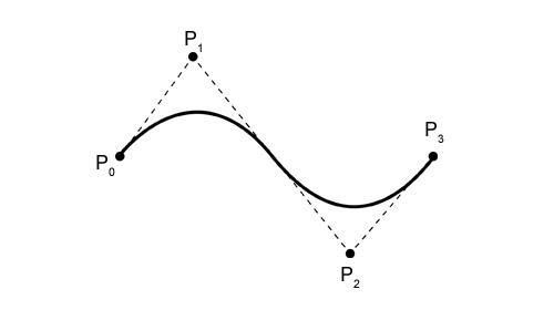
    Bezier curve is the name given to the parametric curve controlled by a set of points. Used often in computer graphics, animations and fonts, Quadratic Bezier curves are composited together to form a sequence of curves.
    [/av_textblock]

    [av_heading tag=’h1′ padding=’10’ heading=’Properties’ color=” style=” custom_font=” size=” subheading_active=” subheading_size=’15’ custom_class=” admin_preview_bg=” av-desktop-hide=” av-medium-hide=” av-small-hide=” av-mini-hide=” av-medium-font-size-title=” av-small-font-size-title=” av-mini-font-size-title=” av-medium-font-size=” av-small-font-size=” av-mini-font-size=”]
    Stuff we will put here woohoo…
    [/av_heading]

    [av_textblock size=” font_color=” color=” av-medium-font-size=” av-small-font-size=” av-mini-font-size=” admin_preview_bg=”]
    As defined by Pierre Bezier

    1. The Bezier curve is always constrained to a polygon called a convex hull determined by it’s control points.
    2. The shape of the curve generally follows the shape of the polygon; the first and last points of the curve fall on the first and last points of the polygon.
    3. The degree of the polynomial is the number of control points minus one.
    4. The order of the polynomial is equal to the number of control points.
    5. Bezier curves exhibit the variation diminishing property; the curves are smoother than the polygon defined by the control points.

    [/av_textblock]

    [av_heading tag=’h2′ padding=’10’ heading=’Parametric Equation of a Bezier Curve’ color=” style=’blockquote modern-quote’ custom_font=” size=” subheading_active=” subheading_size=’15’ custom_class=” admin_preview_bg=” av-desktop-hide=” av-medium-hide=” av-small-hide=” av-mini-hide=” av-medium-font-size-title=” av-small-font-size-title=” av-mini-font-size-title=” av-medium-font-size=” av-small-font-size=” av-mini-font-size=”][/av_heading]

    [av_textblock size=” font_color=” color=” av-medium-font-size=” av-small-font-size=” av-mini-font-size=” admin_preview_bg=”]

    Where,

    • p(t) = any point falling on the Bezier curve
    • Bi= ith control point of the Bezier curve
    • n= degree of curve
    • Jn,i(t)= blending function = C(n,i)ti(1-t)n-i where C(n,i) =n!/i!(n-i)!

    [/av_textblock]

    [av_heading tag=’h1′ padding=’10’ heading=’Composite Bezier Curves’ color=” style=” custom_font=” size=” subheading_active=” subheading_size=’15’ custom_class=” admin_preview_bg=” av-desktop-hide=” av-medium-hide=” av-small-hide=” av-mini-hide=” av-medium-font-size-title=” av-small-font-size-title=” av-mini-font-size-title=” av-medium-font-size=” av-small-font-size=” av-mini-font-size=”][/av_heading]

    [av_textblock size=” font_color=” color=” av-medium-font-size=” av-small-font-size=” av-mini-font-size=” admin_preview_bg=”]
    By using a series of Bezier control cages, tangent points can be stitched together and formed into a composite that resembles a curved drawing. This can be used for modeling anything that needs to be displayed or drawn in a curved/cursive fashion.
    [/av_textblock]

    [av_heading tag=’h1′ padding=’10’ heading=’Conclusion’ color=” style=” custom_font=” size=” subheading_active=” subheading_size=’15’ custom_class=” admin_preview_bg=” av-desktop-hide=” av-medium-hide=” av-small-hide=” av-mini-hide=” av-medium-font-size-title=” av-small-font-size-title=” av-mini-font-size-title=” av-medium-font-size=” av-small-font-size=” av-mini-font-size=”][/av_heading]

    [av_textblock size=” font_color=” color=” av-medium-font-size=” av-small-font-size=” av-mini-font-size=” admin_preview_bg=”]
    Through stitching together tangent vector points with their contained Bezier curve, letters could be fashioned in cursive on Proposal Bot.
    [/av_textblock]

    [av_heading tag=’h1′ padding=’10’ heading=’References/Resources’ color=” style=” custom_font=” size=” subheading_active=” subheading_size=’15’ custom_class=” admin_preview_bg=” av-desktop-hide=” av-medium-hide=” av-small-hide=” av-mini-hide=” av-medium-font-size-title=” av-small-font-size-title=” av-mini-font-size-title=” av-medium-font-size=” av-small-font-size=” av-mini-font-size=”][/av_heading]

    [av_textblock size=” font_color=” color=” av-medium-font-size=” av-small-font-size=” av-mini-font-size=” admin_preview_bg=”]

    1. https://www.gatevidyalay.com/bezier-curve-in-computer-graphics-examples/

    [/av_textblock]

    [/av_one_full]

  • Omnidirectional Motion Analysis

    Omnidirectional Motion Analysis

    [av_one_full first min_height=” vertical_alignment=” space=” custom_margin=” margin=’0px’ padding=’0px’ border=” border_color=” radius=’0px’ background_color=” src=” background_position=’top left’ background_repeat=’no-repeat’ animation=”]

    [av_textblock size=’35’ font_color=” color=” av-medium-font-size=” av-small-font-size=” av-mini-font-size=” admin_preview_bg=”]
    Proposal Bot/Spring/2020
    [/av_textblock]

    [av_hr class=’default’ height=’50’ shadow=’no-shadow’ position=’center’ custom_border=’av-border-thin’ custom_width=’50px’ custom_border_color=” custom_margin_top=’30px’ custom_margin_bottom=’30px’ icon_select=’yes’ custom_icon_color=” icon=’ue808′ font=’entypo-fontello’ admin_preview_bg=”]

    [av_textblock size=’30’ font_color=’custom’ color=” av-medium-font-size=” av-small-font-size=” av-mini-font-size=” admin_preview_bg=”]
    Omnidirectional Motion Analysis
    [/av_textblock]

    [av_textblock size=” font_color=’custom’ color=’#bfbfbf’ av-medium-font-size=” av-small-font-size=” av-mini-font-size=” admin_preview_bg=”]
    Author/s: Tyler Galgas

    [/av_textblock]

    [av_hr class=’short’ height=’50’ shadow=’no-shadow’ position=’left’ custom_border=’av-border-thin’ custom_width=’50px’ custom_border_color=” custom_margin_top=’30px’ custom_margin_bottom=’30px’ icon_select=’yes’ custom_icon_color=” icon=’ue808′ font=’entypo-fontello’ admin_preview_bg=”]

    [av_heading tag=’h1′ padding=’10’ heading=’Introduction ‘ color=” style=” custom_font=” size=” subheading_active=” subheading_size=’15’ custom_class=” admin_preview_bg=” av-desktop-hide=” av-medium-hide=” av-small-hide=” av-mini-hide=” av-medium-font-size-title=” av-small-font-size-title=” av-mini-font-size-title=” av-medium-font-size=” av-small-font-size=” av-mini-font-size=”][/av_heading]

    [av_textblock size=” font_color=” color=” av-medium-font-size=” av-small-font-size=” av-mini-font-size=” admin_preview_bg=”]
    Omni directional movement allows for the path of Proposal Bot to move diagonally and side ways, along with forwards and backwards.
    [/av_textblock]

    [av_heading tag=’h1′ padding=’10’ heading=’Mecanum Wheels’ color=” style=” custom_font=” size=” subheading_active=” subheading_size=’15’ custom_class=” admin_preview_bg=” av-desktop-hide=” av-medium-hide=” av-small-hide=” av-mini-hide=” av-medium-font-size-title=” av-small-font-size-title=” av-mini-font-size-title=” av-medium-font-size=” av-small-font-size=” av-mini-font-size=”]
    Stuff we will put here woohoo…
    [/av_heading]

    [av_textblock size=” font_color=” color=” av-medium-font-size=” av-small-font-size=” av-mini-font-size=” admin_preview_bg=”]

    Mecanum wheels are a tireless wheel that instead uses a series of external rollers around the entirety of the rim. Each wheel moves independently with its own powertrain, which allows for movement in a vectored path by utilizing diagonal forces
    [/av_textblock]

    [av_heading tag=’h2′ padding=’10’ heading=’How They Work’ color=” style=’blockquote modern-quote’ custom_font=” size=” subheading_active=” subheading_size=’15’ custom_class=” admin_preview_bg=” av-desktop-hide=” av-medium-hide=” av-small-hide=” av-mini-hide=” av-medium-font-size-title=” av-small-font-size-title=” av-mini-font-size-title=” av-medium-font-size=” av-small-font-size=” av-mini-font-size=”][/av_heading]

    [av_textblock size=” font_color=” color=” av-medium-font-size=” av-small-font-size=” av-mini-font-size=” admin_preview_bg=”]

    All 4 wheels in the same direction results in forward/backward movements since longitudinal force vectors add up but the transverse vectors cancel each other out. The rollers are positioned at a 45 degree angle to the axis of rotation of the wheel. By applying the force at an angle to the robot, the magnitude of the force vectors can be controlled which allows the robot to traverse in any direction while staying in a constant compass position.
    [/av_textblock]

    [av_heading tag=’h1′ padding=’10’ heading=’Conclusion’ color=” style=” custom_font=” size=” subheading_active=” subheading_size=’15’ custom_class=” admin_preview_bg=” av-desktop-hide=” av-medium-hide=” av-small-hide=” av-mini-hide=” av-medium-font-size-title=” av-small-font-size-title=” av-mini-font-size-title=” av-medium-font-size=” av-small-font-size=” av-mini-font-size=”][/av_heading]

    [av_textblock size=” font_color=” color=” av-medium-font-size=” av-small-font-size=” av-mini-font-size=” admin_preview_bg=”]

    Through coding and control in the Artxterra app, Proposal Bot is capable to move in an omnidirectional motion which allows for free range of movement when writing out “M-A-R-R-Y  M-E ”
    [/av_textblock]

    [av_heading tag=’h1′ padding=’10’ heading=’References/Resources’ color=” style=” custom_font=” size=” subheading_active=” subheading_size=’15’ custom_class=” admin_preview_bg=” av-desktop-hide=” av-medium-hide=” av-small-hide=” av-mini-hide=” av-medium-font-size-title=” av-small-font-size-title=” av-mini-font-size-title=” av-medium-font-size=” av-small-font-size=” av-mini-font-size=”][/av_heading]

    [av_textblock size=” font_color=” color=” av-medium-font-size=” av-small-font-size=” av-mini-font-size=” admin_preview_bg=”]

    1. https://www.roboteq.com/index.php/component/easyblog/entry/driving-mecanum-wheels-omnidirectional-robots?Itemid=1208
    2. https://howtomechatronics.com/projects/arduino-mecanum-wheels-robot/

    [/av_textblock]

    [/av_one_full]

  • HC-05 Bluetooth Module Analysis

    HC-05 Bluetooth Module Analysis

    [av_one_full first min_height=” vertical_alignment=” space=” custom_margin=” margin=’0px’ padding=’0px’ border=” border_color=” radius=’0px’ background_color=” src=” background_position=’top left’ background_repeat=’no-repeat’ animation=”]

    [av_textblock size=’35’ font_color=” color=” av-medium-font-size=” av-small-font-size=” av-mini-font-size=” admin_preview_bg=”]
    Proposal Bot/Spring/2020
    [/av_textblock]

    [av_hr class=’default’ height=’50’ shadow=’no-shadow’ position=’center’ custom_border=’av-border-thin’ custom_width=’50px’ custom_border_color=” custom_margin_top=’30px’ custom_margin_bottom=’30px’ icon_select=’yes’ custom_icon_color=” icon=’ue808′ font=’entypo-fontello’ admin_preview_bg=”]

    [av_textblock size=’30’ font_color=’custom’ color=” av-medium-font-size=” av-small-font-size=” av-mini-font-size=” admin_preview_bg=”]
    HC-05 Bluetooth Module Analysis
    [/av_textblock]

    [av_textblock size=” font_color=’custom’ color=’#bfbfbf’ av-medium-font-size=” av-small-font-size=” av-mini-font-size=” admin_preview_bg=”]
    Author: Ethan Thiessa

    [/av_textblock]

    [av_hr class=’short’ height=’50’ shadow=’no-shadow’ position=’left’ custom_border=’av-border-thin’ custom_width=’50px’ custom_border_color=” custom_margin_top=’30px’ custom_margin_bottom=’30px’ icon_select=’yes’ custom_icon_color=” icon=’ue808′ font=’entypo-fontello’ admin_preview_bg=”]

    [av_textblock size=” font_color=” color=”]

    [/av_textblock]

    [av_heading tag=’h1′ padding=’10’ heading=’Introduction ‘ color=” style=” custom_font=” size=” subheading_active=” subheading_size=’15’ custom_class=” admin_preview_bg=” av-desktop-hide=” av-medium-hide=” av-small-hide=” av-mini-hide=” av-medium-font-size-title=” av-small-font-size-title=” av-mini-font-size-title=” av-medium-font-size=” av-small-font-size=” av-mini-font-size=”][/av_heading]

    [av_textblock size=” font_color=” color=” av-medium-font-size=” av-small-font-size=” av-mini-font-size=” admin_preview_bg=”]

    Figure 1. HC-05 Bluetooth Module Diagrams

    This HC-05 Bluetooth module, made by DSD Tech, has two types of modes: Configuration mode and Transparent mode. In configuration mode, the enable pin is connected to a 3.3V power source which allows you to use the button on the device to turn it on or off. In transparent Mode, the enable pin is floated and the AT command is not responsive.

    The HC-05 Bluetooth module has 6 pins: enable, Vcc, Ground, Tx, Rx, and State, and Vcc can be powered from 3.3V – 6V. For our project, enable and state are floated, Vcc and ground are connected to the Arduino Uno’s 5V supply and ground, and TX and RX from the module are connected to the Arduino’s RX and TX serial pins accordingly. 

    Explanation of RX and TX:

    The RX and TX pins on the Arduino Uno are used to receive (RX) and transmit (TX) TTL serial data. When using serial communication at TTL (Transistor-Transistor Logic) level the logic level will always be between 0V and Vcc. With this in mind, the logic high (1) is represented by Vcc and the logic low (0) is represented by 0V.
    [/av_textblock]

    [av_heading tag=’h1′ padding=’10’ heading=’ATmega328P Voltage Logic Characteristics’ color=” style=” custom_font=” size=” subheading_active=” subheading_size=’15’ custom_class=” admin_preview_bg=” av-desktop-hide=” av-medium-hide=” av-small-hide=” av-mini-hide=” av-medium-font-size-title=” av-small-font-size-title=” av-mini-font-size-title=” av-medium-font-size=” av-small-font-size=” av-mini-font-size=”]
    Stuff we will put here woohoo…
    [/av_heading]

    [av_textblock size=” font_color=” color=” av-medium-font-size=” av-small-font-size=” av-mini-font-size=” admin_preview_bg=”]

    Figure 2. ATmega328P Input and output Logic Voltage characteristics

    When we look at the ATmega328P Input and output logic voltage characteristics, we see that the minimum input high voltage of the Arduino is VIH = 0.6VCC when VCC is between 2.7V-5.5V. The minimum output high voltage that the Arduino can transmit is VOH = 4.1V when VCC is at 5V

    Therefore,

    Min. VIH = 0.6*Vcc = 0.6*5 = 3V                  Min. VOH = 4.1V
    [/av_textblock]

    [av_heading tag=’h2′ padding=’10’ heading=’HC-05 Logic Voltage Characteristics’ color=” style=’blockquote modern-quote’ custom_font=” size=” subheading_active=” subheading_size=’15’ custom_class=” admin_preview_bg=” av-desktop-hide=” av-medium-hide=” av-small-hide=” av-mini-hide=” av-medium-font-size-title=” av-small-font-size-title=” av-mini-font-size-title=” av-medium-font-size=” av-small-font-size=” av-mini-font-size=”][/av_heading]

    [av_textblock size=” font_color=” color=” av-medium-font-size=” av-small-font-size=” av-mini-font-size=” admin_preview_bg=”]
    Below is the circuit schematic for the HC-05 from DSD Tech. From the datasheet, the HC-05 module can be powered from 3.3V-6V but has a 3.3V logic level voltage. This 3.3V logic level is obtained via an on-chip linear regulator on the Bluetooth module that converts the Vcc voltage to a regulated 3.3V. From DSD Tech’s datasheet, they claim that the logic voltage from the linear regulator ranges from (3.1V~4.2V) with the current in pairing in the range of 30~40mA. 

    Figure 3. HC-05 Circuit Schematic
    Figure 4-5. Datasheet of ITead Studio & REYAX

    Comparing Other Companies HC-05 Bluetooth Module

    To see if DSD Tech’s claim of their absolute ratings of the logic voltage of their chip were valid I looked at other companies who make the same Bluetooth module. Looking at two different companies, ITead Studio and REYAX, their on board linear regulators had the same characteristics of DSD Tech’s module with ITead Studio having a slightly better minimum voltage of 3.15V.
    [/av_textblock]

    [av_heading tag=’h1′ padding=’10’ heading=’Why do we need a resistor voltage divider on the Arduino TX line to HC-05 RX pin?’ color=” style=” custom_font=” size=” subheading_active=” subheading_size=’15’ custom_class=” admin_preview_bg=” av-desktop-hide=” av-medium-hide=” av-small-hide=” av-mini-hide=” av-medium-font-size-title=” av-small-font-size-title=” av-mini-font-size-title=” av-medium-font-size=” av-small-font-size=” av-mini-font-size=”][/av_heading]

    [av_textblock size=” font_color=” color=” av-medium-font-size=” av-small-font-size=” av-mini-font-size=” admin_preview_bg=”]
    Given:

    Arduino:

    Min VIH = 3V                VIH = Input high Logic Voltage

    Min VOH = 4.1V            VOH= Output high Logic Voltage

    HC-05:

    Max VIH = 4.2V

    Min VOH = 3.1V         

    When we look at the minimum output high logic voltage that the Arduino can transmit to the HC-05, we see that the minimum output of the Arduino is VOH= 4.1V compared to the max input that the HC-05 can receive at VIH = 4.2V. Since the minimum input voltage of the Arduino is only 100mV more than the max input of the HC-05, there is a high chance that the HC-05 can be damaged when the Arduino TX is connected directly to the HC-05 RX. To avoid this damage, a resistor voltage divider from the Arduino TX pin to the HC-05 RX pin is needed to lower the 5V Vcc from the Arduino power to a 3.3V logic, so that data can be transferred safely to the Bluetooth Module. 
    [/av_textblock]

    [av_heading tag=’h2′ padding=’10’ heading=’Why do we not need a voltage divider on the HC-05 TX line to Arduino RX pin?’ color=” style=’blockquote modern-quote’ custom_font=” size=” subheading_active=” subheading_size=’15’ custom_class=” admin_preview_bg=” av-desktop-hide=” av-medium-hide=” av-small-hide=” av-mini-hide=” av-medium-font-size-title=” av-small-font-size-title=” av-mini-font-size-title=” av-medium-font-size=” av-small-font-size=” av-mini-font-size=”][/av_heading]

    [av_textblock size=” font_color=” color=” av-medium-font-size=” av-small-font-size=” av-mini-font-size=” admin_preview_bg=”]
    A voltage divider is not needed between the HC-05 TX line to Arduino RX because the minimum high logic voltage that the Arduino can receive is  VIH = 3V and the HC-05 will always be able to supply enough voltage since the minimum logic output that the HC-05 can transmit is VOH = 3.1V. With the typical VOH of the HC-05 being 3.3V, there should not be a problem with the Arduino registering the Bluetooth’s transmitted data as a logic high(1).
    [/av_textblock]

    [av_heading tag=’h1′ padding=’10’ heading=’Conclusion’ color=” style=” custom_font=” size=” subheading_active=” subheading_size=’15’ custom_class=” admin_preview_bg=” av-desktop-hide=” av-medium-hide=” av-small-hide=” av-mini-hide=” av-medium-font-size-title=” av-small-font-size-title=” av-mini-font-size-title=” av-medium-font-size=” av-small-font-size=” av-mini-font-size=”][/av_heading]

    [av_textblock size=” font_color=” color=” av-medium-font-size=” av-small-font-size=” av-mini-font-size=” admin_preview_bg=”]
    In conclusion, the HC-05 should be able to communicate with the Arduino without issue, given that we use a resistor divider on the Arduino TX pin to the HC-05 RX pin to set the voltage to 3.3V. As far as using this Bluetooth module for our project, the Bluetooth module uses Bluetooth 2.0 technology which is compatible with Android phones but not with IOS given that the module would have to use the current Bluetooth 4.0 technology. Since we are using an Android phone to run the ArxRobot application, the Bluetooth module will not have issues communicating to the phone to run the app.
    [/av_textblock]

    [av_heading tag=’h1′ padding=’10’ heading=’References/Resources’ color=” style=” custom_font=” size=” subheading_active=” subheading_size=’15’ custom_class=” admin_preview_bg=” av-desktop-hide=” av-medium-hide=” av-small-hide=” av-mini-hide=” av-medium-font-size-title=” av-small-font-size-title=” av-mini-font-size-title=” av-medium-font-size=” av-small-font-size=” av-mini-font-size=”][/av_heading]

    [av_textblock size=” font_color=” color=” av-medium-font-size=” av-small-font-size=” av-mini-font-size=” admin_preview_bg=”]

    1. http://www.dsdtech-global.com/2017/08/hc-05-datasheet-and-how-to-enter-at.html
    2. https://www.electronicaestudio.com/docs/istd016A.pdf
    3. http://cesaretopia.com/wp-content/uploads/2017/03/Modulo-Bt.pdf

    [/av_textblock]

    [/av_one_full]

  • Buck Converter Analysis

    Buck Converter Analysis

    [av_one_full first min_height=” vertical_alignment=” space=” custom_margin=” margin=’0px’ padding=’0px’ border=” border_color=” radius=’0px’ background_color=” src=” background_position=’top left’ background_repeat=’no-repeat’ animation=”]

    [av_textblock size=’35’ font_color=” color=” av-medium-font-size=” av-small-font-size=” av-mini-font-size=” admin_preview_bg=”]
    Proposal Bot/Spring/2020
    [/av_textblock]

    [av_hr class=’default’ height=’50’ shadow=’no-shadow’ position=’center’ custom_border=’av-border-thin’ custom_width=’50px’ custom_border_color=” custom_margin_top=’30px’ custom_margin_bottom=’30px’ icon_select=’yes’ custom_icon_color=” icon=’ue808′ font=’entypo-fontello’ admin_preview_bg=”]

    [av_textblock size=’30’ font_color=’custom’ color=” av-medium-font-size=” av-small-font-size=” av-mini-font-size=” admin_preview_bg=”]
    Buck Converter Analysis
    [/av_textblock]

    [av_textblock size=” font_color=’custom’ color=’#bfbfbf’ av-medium-font-size=” av-small-font-size=” av-mini-font-size=” admin_preview_bg=”]
    Author: Ethan Thiessa

    [/av_textblock]

    [av_hr class=’short’ height=’50’ shadow=’no-shadow’ position=’left’ custom_border=’av-border-thin’ custom_width=’50px’ custom_border_color=” custom_margin_top=’30px’ custom_margin_bottom=’30px’ icon_select=’yes’ custom_icon_color=” icon=’ue808′ font=’entypo-fontello’ admin_preview_bg=”]

    [av_textblock size=” font_color=” color=”]

    [/av_textblock]

    [av_heading tag=’h1′ padding=’10’ heading=’Introduction ‘ color=” style=” custom_font=” size=” subheading_active=” subheading_size=’15’ custom_class=” admin_preview_bg=” av-desktop-hide=” av-medium-hide=” av-small-hide=” av-mini-hide=” av-medium-font-size-title=” av-small-font-size-title=” av-mini-font-size-title=” av-medium-font-size=” av-small-font-size=” av-mini-font-size=”][/av_heading]

    [av_textblock size=” font_color=” color=” av-medium-font-size=” av-small-font-size=” av-mini-font-size=” admin_preview_bg=”]
    To operate our buck converter, I chose an LM2596 simple switcher 3A step down voltage regulator where the datasheet can be found here. The LM2596 can take input voltages up to 40V and output voltages down to 1.2V – 37V with a 3A output load current. The LM2596 can be used in four configurations with an output of 3.3V, 5V, 12V, and adjustable voltage output. 
    [/av_textblock]

    [av_heading tag=’h1′ padding=’10’ heading=’Electrical Characteristics of LM2596′ color=” style=” custom_font=” size=” subheading_active=” subheading_size=’15’ custom_class=” admin_preview_bg=” av-desktop-hide=” av-medium-hide=” av-small-hide=” av-mini-hide=” av-medium-font-size-title=” av-small-font-size-title=” av-mini-font-size-title=” av-medium-font-size=” av-small-font-size=” av-mini-font-size=”]
    Stuff we will put here woohoo…
    [/av_heading]

    [av_textblock size=” font_color=” color=” av-medium-font-size=” av-small-font-size=” av-mini-font-size=” admin_preview_bg=”]

    Figure 1. Electrical Characteristics for adjustable voltage regulator

    As seen from the datasheet above, using the adjustable voltage version of the LM2596, they were able to get a typical 73% power efficiency when the input was 12V and the output was 3V with a 3A load current. The efficiency and performance of the voltage regulator are affected by the external components used such as the diode rectifier, inductor, and input and output capacitors, which makes choosing the external components crucial to a well-performing voltage regulator.

    Figure 2. 11.1V Lithium Battery

    For our project we are using an 11.1V lithium-ion battery to provide enough current to power the 4 stepper motors for the wheels that need a minimum of 8.5V and approximately 600mA- 1000mA to run. The battery we are using is rated at 3S 2200mAh 45C, so the theoretical max current draw is 2200mA * 45C = 99A. This is more than enough current to power our four stepper motors and two servos for the actuation of the ring box and pen plotter.
    [/av_textblock]

    [av_heading tag=’h2′ padding=’10’ heading=’Buck Converter Design’ color=” style=’blockquote modern-quote’ custom_font=” size=” subheading_active=” subheading_size=’15’ custom_class=” admin_preview_bg=” av-desktop-hide=” av-medium-hide=” av-small-hide=” av-mini-hide=” av-medium-font-size-title=” av-small-font-size-title=” av-mini-font-size-title=” av-medium-font-size=” av-small-font-size=” av-mini-font-size=”][/av_heading]

    [av_textblock size=” font_color=” color=” av-medium-font-size=” av-small-font-size=” av-mini-font-size=” admin_preview_bg=”]

    Figure 3. LM2596 Adjustable Voltage configuration

    The circuit configuration for the LM2596 that was used for the Proposal Bot PCB was found on ElecCircuit.com. In this configuration of the buck converter, we have three different capacitors, a diode, an inductor, and two resistors forming a voltage divider. 

    Input and Output Filter Capacitors (C1 and C2)

    The input filter capacitor (C1) is used on the power rails of the input of the LM2596, in order to lower the voltage transients going into the voltage regulator along with supplying the switching currents required by the regulator. We are using a fairly large 470uF electrolytic capacitor to filter out unwanted frequencies from our lithium battery power supply. This capacitor is also responsible for eliminating glitch power, which can dissipate 20%-70% of the total power. Removal of these glitches will allow the regulator to have steady switching activity.

    The output filter capacitor (C2) is used on the power rails of the output of the LM2596. This capacitor is used to further smooth out the DC voltage on the output of the voltage regulator in order to get a steady output voltage. For our project, we are using a 220uF electrolytic capacitor in order to achieve a steady output voltage for our servo motors.

    Feedforward Capacitor (C3)

    The C3 capacitor is used as a feedforward capacitor which is placed across the high-side feedback resistor. This feedforward capacitor adds an extra pole and zero to the control loop, which can improve the phase margin and bandwidth of the regulator circuit. This is a commonly used method to improve the stability and bandwidth of a power supply to obtain a more efficient control system. For our project, we are using a 3.3nF ceramic capacitor to achieve a more stable system.

    Shottky Rectifier Diode (D1)

    The D1 Schottky rectifier diode is placed along the output of the LM2596 and the ground rail of the buck converter. The diode is going to act as a catch diode for the LM2596. With the maximum current rating being 1.2 times greater than the max load current, it should be able to withstand a continuous output short. The reverse voltage of the diode should be at least 1.25 times the maximum input voltage. For our design, we used an SBR1045 super barrier diode which has a max current rating of 10A and a max reverse voltage of 32V. This is more than enough for our design to power our motors and keep the LM2596 running efficiently.

    Calculations

    Design:

    Max Current Draw: 1.2A

    Max Voltage: 11.1V

    Diode Characteristics Needed:

    Max Current Rating: 1.2*1.2A = 1.44A

    Max Reverse Voltage: 1.25*11.1V = 13.88V

    SBR1045 Diode:

    Max Current Rating: 10A

    Max Reverse Voltage: 32V

    Inductor (L1)

    The inductor for this design is placed on the ouput of the LM2596 to help with energy conversion for the linear regulator. There is a couple of equations used to help us pick the best Inductor for our design. The first equation below is used to calculate the inductor Volt x Microsecond [V x µs} constant.

    Calculating Constant:

    Then to calculate the inductance needed we can rearrange the equation below knowing that the current rating we want for our inductor needs to be 1.15 * ILoad.

    Calculating Inductance:

    As seen from the calculation above, the optimum inductance for our design is 82uH. We decided to go with a 68uH inductor, as they are more prevalent and it still fulfills the requirements of our design.

    Voltage Divider Resistors (R1 and R2)

    The two resistors on the output of the LM2596 are used to program the output voltage on the LM2596. 

    The equation to choose the correct resistor pair is shown above, where Vref = 1.23V is the minimum output voltage of the LM2596. From the LM2596 datasheet, R1 should be chosen to be between 1k ohms and 5k ohms. After choosing R1, you can use the equation below to calculate the resistance needed to obtain your desired output voltage for the buck converter.

    For our design, we needed a 6V output for our Buck converter to power our servo motors. To obtain this output voltage we would use the equation above to calculate R2. Using this equation and choosing 5k ohms for R1 we obtain R2 = 5k*(6V/1.23V – 1.0) = 19,390 ohms. Since a resistor with that ohm rating is hard to obtain we used R2 = 20k ohms to obtain the desired output.

    Using these two resistors the theoretical output for our buck converter should be 

    This output is within 0.2V of our desired output voltage, so we can accept the output.
    [/av_textblock]

    [av_heading tag=’h1′ padding=’10’ heading=’Measured Input/Output Voltages on PCB’ color=” style=” custom_font=” size=” subheading_active=” subheading_size=’15’ custom_class=” admin_preview_bg=” av-desktop-hide=” av-medium-hide=” av-small-hide=” av-mini-hide=” av-medium-font-size-title=” av-small-font-size-title=” av-mini-font-size-title=” av-medium-font-size=” av-small-font-size=” av-mini-font-size=”][/av_heading]

    [av_textblock size=” font_color=” color=” av-medium-font-size=” av-small-font-size=” av-mini-font-size=” admin_preview_bg=”]

    Figure 4. Measured Input Voltage
    Figure 5. Measured Output Voltage

    As seen from the figures above, the measured input voltage going into the LM2596 measured to be 11.13V, 30mV higher than the normal voltage, and the output measured to be 6.08V which is 70mV lower than the theoretical output voltage. This output works in our favor as it is now closer to 6V, but deviates slightly from the theoretical output voltage.
    [/av_textblock]

    [av_heading tag=’h1′ padding=’10’ heading=’Conclusion’ color=” style=” custom_font=” size=” subheading_active=” subheading_size=’15’ custom_class=” admin_preview_bg=” av-desktop-hide=” av-medium-hide=” av-small-hide=” av-mini-hide=” av-medium-font-size-title=” av-small-font-size-title=” av-mini-font-size-title=” av-medium-font-size=” av-small-font-size=” av-mini-font-size=”][/av_heading]

    [av_textblock size=” font_color=” color=” av-medium-font-size=” av-small-font-size=” av-mini-font-size=” admin_preview_bg=”]
    In conclusion, with the components chosen for this buck converter configuration, we were able to obtain an output voltage that is within 100mV of our desired output voltage to power our servo motors. For future reference, an output voltage of 5.5V would be more desirable for powering servos, since it gives you a better range of servos you can use for your project. With the 6V configuration, you are limited to using bigger servo motors that can handle 6V, since most small servo motors have a max rating of 6V. A variable resistor for R2 would’ve been a better design for this buck converter configuration, allowing the user to adjust the output voltage to fit the parameters of their requirements. 
    [/av_textblock]

    [av_heading tag=’h1′ padding=’10’ heading=’References/Resources’ color=” style=” custom_font=” size=” subheading_active=” subheading_size=’15’ custom_class=” admin_preview_bg=” av-desktop-hide=” av-medium-hide=” av-small-hide=” av-mini-hide=” av-medium-font-size-title=” av-small-font-size-title=” av-mini-font-size-title=” av-medium-font-size=” av-small-font-size=” av-mini-font-size=”][/av_heading]

    [av_textblock size=” font_color=” color=” av-medium-font-size=” av-small-font-size=” av-mini-font-size=” admin_preview_bg=”]

    1. https://www.onsemi.com/pub/Collateral/LM2596-D.PDF
    2. https://www.eleccircuit.com/regulator-switching-dc-to-dc-step-down-voltage-with-lm2596/

    [/av_textblock]

    [/av_one_full]

  • Proposal Bot: PCB Design

    Proposal Bot: PCB Design

    [av_one_full first min_height=” vertical_alignment=” space=” custom_margin=” margin=’0px’ padding=’0px’ border=” border_color=” radius=’0px’ background_color=” src=” background_position=’top left’ background_repeat=’no-repeat’ animation=”]

    [av_textblock size=’35’ font_color=” color=” av-medium-font-size=” av-small-font-size=” av-mini-font-size=” admin_preview_bg=”]
    Proposal Bot/Spring/2020
    [/av_textblock]

    [av_hr class=’default’ height=’50’ shadow=’no-shadow’ position=’center’ custom_border=’av-border-thin’ custom_width=’50px’ custom_border_color=” custom_margin_top=’30px’ custom_margin_bottom=’30px’ icon_select=’yes’ custom_icon_color=” icon=’ue808′ font=’entypo-fontello’ admin_preview_bg=”]

    [av_textblock size=’30’ font_color=’custom’ color=” av-medium-font-size=” av-small-font-size=” av-mini-font-size=” admin_preview_bg=”]
    Proposal Bot PCB Design
    [/av_textblock]

    [av_textblock size=” font_color=’custom’ color=’#bfbfbf’ av-medium-font-size=” av-small-font-size=” av-mini-font-size=” admin_preview_bg=”]
    Author: Ethan Thiessa

    [/av_textblock]

    [av_hr class=’short’ height=’50’ shadow=’no-shadow’ position=’left’ custom_border=’av-border-thin’ custom_width=’50px’ custom_border_color=” custom_margin_top=’30px’ custom_margin_bottom=’30px’ icon_select=’yes’ custom_icon_color=” icon=’ue808′ font=’entypo-fontello’ admin_preview_bg=”]

    [av_textblock size=” font_color=” color=”]

    [/av_textblock]

    [av_heading tag=’h1′ padding=’10’ heading=’Introduction ‘ color=” style=” custom_font=” size=” subheading_active=” subheading_size=’15’ custom_class=” admin_preview_bg=” av-desktop-hide=” av-medium-hide=” av-small-hide=” av-mini-hide=” av-medium-font-size-title=” av-small-font-size-title=” av-mini-font-size-title=” av-medium-font-size=” av-small-font-size=” av-mini-font-size=”][/av_heading]

    [av_textblock size=” font_color=” color=” av-medium-font-size=” av-small-font-size=” av-mini-font-size=” admin_preview_bg=”]
    This is the PCB design for our motor controller shield for Proposal Bot. This shield is designed with 4 stepper motor drivers, a buck converter, and a Bluetooth module. The purpose of this shield design is to control all four stepper motors with the motor controllers along with utilizing a buck converter to step down the 11.1V lithium ion battery, used to power the stepper motors, to 6V, so that we can power two servo motors used to control the ring box motion and up and down response of the pen plotter. This design also utilizes a Bluetooth module that can be used, so that the Proposal Bot movement can also be controlled using the Arxterra App.
    [/av_textblock]

    [av_heading tag=’h1′ padding=’10’ heading=’Preliminary Circuit Diagram’ color=” style=” custom_font=” size=” subheading_active=” subheading_size=’15’ custom_class=” admin_preview_bg=” av-desktop-hide=” av-medium-hide=” av-small-hide=” av-mini-hide=” av-medium-font-size-title=” av-small-font-size-title=” av-mini-font-size-title=” av-medium-font-size=” av-small-font-size=” av-mini-font-size=”]
    Stuff we will put here woohoo…
    [/av_heading]

    [av_textblock size=” font_color=” color=” av-medium-font-size=” av-small-font-size=” av-mini-font-size=” admin_preview_bg=”]
    Before I designed the PCB schematic, I laid out all the parts used in a simple circuit diagram to show how all the connections are made and what each component controls. Since the 3-Dot was not really feasible for Proposal Bot because of its size and the amount of motors that need to be controlled, an Arduino Uno is used to control the motor driver shield. Because the 3-dot wasn’t used, we have to incorporate a Bluetooth module, so that the arduino can communicate with the Arxterra app to control the motion of Proposal Bot. In order to add some complexity to the PCB design, we added a buck converter to take the 11.1V from the lithium ion battery and step it down to 6V to control the servo motors. The buck converter is used to get high current to the servo motors and to avoid using an extra power supply to power these motors.

    Figure 1. Circuit Diagram

    [/av_textblock]

    [av_heading tag=’h2′ padding=’10’ heading=’PCB Schematic’ color=” style=’blockquote modern-quote’ custom_font=” size=” subheading_active=” subheading_size=’15’ custom_class=” admin_preview_bg=” av-desktop-hide=” av-medium-hide=” av-small-hide=” av-mini-hide=” av-medium-font-size-title=” av-small-font-size-title=” av-mini-font-size-title=” av-medium-font-size=” av-small-font-size=” av-mini-font-size=”][/av_heading]

    [av_textblock size=” font_color=” color=” av-medium-font-size=” av-small-font-size=” av-mini-font-size=” admin_preview_bg=”]
    The first schematic is the Motor driver schematic utizlizing the Pololu DRV8825 motor driver carriers. the motor drivers’ main power is from the 11.1V lithium ion battery that is connected via the two terminal block labeled PWR-1 and PWR-2. The 11.1V power supply is connected to VMOT on the motor drivers, which is protected by 100uF capacitors. The RST and SLP connections on the motor driver are connected to a female header that will be connected to the arduino’s 5V power supply in order to power the logic in the motor drivers. The step and direction pins are also connected to the female headers in order for the arduino to connect to those headers to control the motors speed and direction. Finally the B2, B1, A1, and A2 pins are connected to a female header, so that the stepper motors can be easily connected to the motor drivers.

    Figure 2. Motor Driver Schematic

    The buck converter utilizes a LM2596, a 3A step down voltage regulator in the surface mount package, to step down the 11.1V from the lithium ion battery to 6V. This step down is achieved from the voltage divider from R1 and R2 where R2 = R1{(Vout/Vref)-1}. The output of the buck converter is two 6v outputs that are connected to female headers for the servo motors to easily connect to. The buck converter is used in this design instead of a more simple linear regulator or another external power supply for a few reasons. Because we are using motor driver carriers that are easily connected using headers we had to add some complexity to our circuit design. For this reason we used a buck converter so that we can add intricacy to the design along with fulfill the design requirement of having a surface mount part. If we were to simplify the circuit, a linear regulator would be the better choice to conserve more space or another external power supply could be added to power the servo motors with the tradeoff of weight and size of Proposal Bot.

    Figure 3. Buck Converter Schematic

    [/av_textblock]

    [av_heading tag=’h1′ padding=’10’ heading=’References/Resources’ color=” style=” custom_font=” size=” subheading_active=” subheading_size=’15’ custom_class=” admin_preview_bg=” av-desktop-hide=” av-medium-hide=” av-small-hide=” av-mini-hide=” av-medium-font-size-title=” av-small-font-size-title=” av-mini-font-size-title=” av-medium-font-size=” av-small-font-size=” av-mini-font-size=”][/av_heading]

    [av_textblock size=” font_color=” color=” av-medium-font-size=” av-small-font-size=” av-mini-font-size=” admin_preview_bg=”]

    1. http://www.ti.com/lit/ds/symlink/lm2596.pdf
    2. https://www.eleccircuit.com/regulator-switching-dc-to-dc-step-down-voltage-with-lm2596/

    [/av_textblock]

    [/av_one_full]