Author: Lucas Gutierrez

  • Read from EEPROM

    Read from EEPROM

    By: Matt Shellhammer (Electronics & Control Engineer)

    Approved by: Lucas Gutierrez (Project Manager)

    Table of Contents

    Introduction

    When in play back mode the robots will be reading data that was previously stored in EEPROM while being controlled by the Arxterra App. What is being read from EEPROM is the direction that the robot was facing and the turn that the robot took at every decision point. This will allow the robot autonomously navigate throughout the maze since it will have the decision stored for every decision point throughout the robots path. For rooms such as hallways, corners, and a dead end the robot will always choose the same turn value so that does not require reading from EEPROM.

    Methodology

    This software is developed to read data about direction and turn value every time a decision is made (room types 1, 2, and 4). It stores reads the data from EEPROM starting again at the address 0x0000. Every time the robot reaches a decision point, it will read the turn and direction value for that decision point and then use that to make its decision. The software in subroutines.ino file is the same as the subroutines.ino file in the blog post “Write to EEPROM”. The software specific to read EEPROM is in orange text within the EEPROM_Write.ino file below.

    The roomType subroutine determines what room you’re in using “hitWall”, “rightHit”, and “leftHit”. “hitWall” ands the room value with a byte value from hit_table that is determined by the direction of the robot. The result will either be true or false depending if the robot is facing a wall or not. Then “rightHit” and “leftHit” just turns the robot and then implements hitWall again within the subroutines and determines if there’s a wall on the right and the left of the robot. This is then used to determine when a decision is required and when direction and turn must be read from EEPROM.

    Data is read as follows:

    Address Value
    0x0000 Direction (decision 1)
    0x0001 Turn (decision 1)
    0x0002 Direction (decision 2)
    0x0003 Turn (decision 2)
    0x0004 Direction (decision 3)

    Software

    EEPROM_Write.ino (MAIN SETUP & LOOP)

    ////////////////////////////////////////////////////////////////
    //  Name     : EEPROM Read maze data                          //
    //  Author   : Matt Shellhammer                               //
    //  Date     : 2 December, 2017                               //
    //  Version  : 1.0                                            //
    ////////////////////////////////////////////////////////////////
    
    #define __PROG_TYPES_COMPAT__ // __PROG_TYPES_COMPAT__
    #include <avr/pgmspace.h>
    #include <Robot3DoTBoard.h>
    #include <EEPROM.h>
    #include <Wire.h>
    #include <Servo.h>
    #include "maze.h"
    
    void setup() {
      Serial.begin(9600);
      delay(5000);
    }
    
    void loop() {
      static uint16_t EEPROM_Idx = 0x0000;    // first EEPROM index is 0x0000
      static uint8_t type = 0;                // initially outside of the maze
      static bool decision;                   // create a variable called decision
      static myRobot_t robot_inst;            // create an instance of myRobot_t called robot_inst
    
      // No decision to be made when in a Hallway or outside of the maze (go straight)
      if ((type == 0)||(type == 5)){decision = false;robot_inst.turn = 0x00;}
      // No decision to be made when in a left corner (turn left)
      if (type == 3){decision = false;robot_inst.turn = 0x10;}
      // No decision to be made when in a right corner (turn right)
      if (type == 6){decision = false;robot_inst.turn = 0x01;}
      // No decision to be made when at a dead end (turn around)
      if (type == 7){decision = false;robot_inst.turn = 0x11;}
      else{decision = true;}
    
      // Call read data to EEPROM when at a decision point
      if ((decision == true)&&(EEPROM_Idx < 0x400)){
        // Call Arxterra custom command to request a turn value
        // Store dir facing and turn value
        uint8_t temp_dir = EEPROM_read(EEPROM_Idx);EEPROM_Idx++;
    //    if (temp_dir != robot_inst.dir){//ERROR: Do something}
        robot_inst.turn = EEPROM_read(EEPROM_Idx);EEPROM_Idx++;
      }
        robot_inst = enterRoom(robot_inst); // Update robot_inst
        type = roomType(robot_inst);        // Determine room type
    }

    maze.h (Structure, array, and variable definitions)

    struct coord_t{
      uint8_t row = 0x13; // Robot is initially outside of the maze
      uint8_t col = 0x00; // Robot is initially outside of the maze
    };
    
    struct myRobot_t{
      uint8_t dir = 0x03;   // Robot is initially facing north
      uint8_t turn = 0x00;  // First action is no turn
      coord_t maze;
      uint8_t room = 0x00;  // Initial room is empty
      uint8_t bees = 0x00;  // No bees present
    };
    
    const uint8_t hit_table[] PROGMEM =
      {0x08,  // South (dir == 0b00)
       0x02,  // East (dir == 0b01)
       0x04,  // West (dir == 0b10)
       0x01}; // North (dir == 0b11)
    
    //Compass   S     E     W     N
    //dir       00    01    10    11
    const uint8_t turn_table[] PROGMEM =
              {0b00, 0b01, 0b10, 0b11, // 00 no turn
               0b10, 0b00, 0b11, 0b01, // 01 turn right
               0b01, 0b11, 0b00, 0b10, // 10 turn left
               0b11, 0b10, 0b01, 0b00  // 11 turn around
               };
    
    //  row   col   dir
    const int8_t map_table[] PROGMEM =
        {1  ,  0, // 00
         0  ,  1, // 01
         0  , -1, // 10
        -1  ,  0  // 11
        };
    
    const int maze_length = 399;
    const uint8_t theMaze[] PROGMEM =
    // 00  01   02   03   04   05   06   07   08   09   0A   0B   0C   0D   0E   0F   10   11   12   13   14
    {0x05,0x09,0x09,0x09,0x09,0x09,0x01,0x03,0x05,0x09,0x09,0x09,0x09,0x09,0x09,0x09,0x29,0x09,0x09,0x09,0x02,  // 00
     0x0C,0x09,0x09,0x03,0x05,0x09,0x0A,0x06,0x06,0x05,0x09,0x09,0x09,0x09,0x09,0x09,0x09,0x03,0x05,0x03,0x06,  // 01
     0x05,0x09,0x0B,0x06,0x06,0x05,0x09,0x0A,0x06,0x0C,0x09,0x09,0x09,0x09,0x09,0x01,0x0B,0x0C,0x0A,0x06,0x06,  // 02
     0x06,0x0D,0x09,0x0A,0x06,0x06,0x05,0x03,0x0C,0x09,0x09,0x03,0x05,0x09,0x09,0x0A,0x05,0x09,0x09,0x08,0x02,  // 03
     0x06,0x05,0x09,0x09,0x0A,0x06,0x06,0x0C,0x09,0x09,0x09,0x0A,0x0C,0x09,0x09,0x03,0x06,0x05,0x09,0x09,0x0A,  // 04
     0x06,0x0C,0x03,0x05,0x09,0x02,0x06,0x05,0x09,0x09,0x09,0x09,0x09,0x09,0x03,0x06,0x06,0x0C,0x03,0x05,0x03,  // 05
     0x06,0x05,0x0A,0x0C,0x03,0x06,0x06,0x06,0x05,0x01,0x03,0x07,0x05,0x03,0x06,0x06,0x06,0x05,0x0A,0x06,0x06,  // 06
     0x06,0x0C,0x09,0x03,0x0E,0x0C,0x08,0x02,0x06,0x06,0x06,0x06,0x06,0x06,0x0C,0x02,0x06,0x0C,0x09,0x02,0x06,  // 07
     0x06,0x05,0x0B,0x0C,0x09,0x09,0x09,0x08,0x02,0x06,0x06,0x06,0x06,0x0C,0x09,0x0A,0x04,0x09,0x0B,0x06,0x06,  // 08
     0x0C,0x08,0x09,0x09,0x09,0x09,0x01,0x01,0x02,0x06,0x0C,0x08,0x08,0x09,0x01,0x09,0x08,0x09,0x03,0x06,0x06,  // 09
     0x05,0x01,0x09,0x09,0x0B,0x07,0x06,0x04,0x02,0x0C,0x09,0x09,0x09,0x03,0x04,0x09,0x03,0x07,0x06,0x06,0x06,  // 0A
     0x06,0x0C,0x09,0x09,0x09,0x02,0x06,0x04,0x02,0x0D,0x09,0x09,0x09,0x0A,0x0C,0x03,0x06,0x06,0x06,0x06,0x06,  // 0B
     0x06,0x05,0x09,0x09,0x09,0x0A,0x06,0x0C,0x0A,0x05,0x09,0x09,0x09,0x09,0x03,0x06,0x06,0x06,0x06,0x06,0x06,  // 0C
     0x06,0x0C,0x09,0x09,0x09,0x03,0x04,0x09,0x09,0x08,0x0B,0x05,0x03,0x05,0x0A,0x06,0x06,0x06,0x06,0x06,0x06,  // 0D
     0x04,0x09,0x09,0x09,0x09,0x08,0x02,0x05,0x01,0x09,0x03,0x06,0x06,0x06,0x05,0x0A,0x0E,0x06,0x06,0x06,0x06,  // 0E
     0x06,0x05,0x09,0x09,0x09,0x09,0x0A,0x0E,0x06,0x07,0x06,0x06,0x06,0x06,0x06,0x05,0x09,0x0A,0x06,0x06,0x06,  // 0F
     0x06,0x0C,0x09,0x09,0x09,0x09,0x09,0x09,0x0A,0x06,0x06,0x06,0x06,0x0E,0x0E,0x06,0x05,0x09,0x0A,0x06,0x06,  // 10
     0x04,0x09,0x09,0x09,0x09,0x09,0x09,0x09,0x09,0x0A,0x0C,0x0A,0x06,0x05,0x09,0x0A,0x06,0x0D,0x09,0x0A,0x06,  // 11
     0x04,0x09,0x09,0x09,0x09,0x09,0x09,0x09,0x09,0x09,0x09,0x09,0x08,0x08,0x09,0x09,0x08,0x09,0x09,0x09,0x0A,  // 12
    };

    subroutines.ino

    /*
     * Write data to EEPROM, NOTE: interrupts are disabled while writing
     * @param uiAddress 16 bit interger pointing to the address of the data to write
     * @param ucData 8 bit value signifying the data being written
     */
    
    void EEPROM_write(uint16_t uiAddress, uint8_t ucData) {
      /*Store SREG value before we disable Interrupts*/
      char SREG_save = SREG;
      noInterrupts();
      /* Wait for completion of any Flash Write
            Note:Only necessary if Flash Memory Manipulation is taking place */
      while(SPMCSR &(1<<SPMEN));
      /* Wait for completion of previous write */
      while(EECR & (1<<EEPE));
      /* Set up address and Data Registers */
      EEAR = uiAddress;
      EEDR = ucData;
      /* Write logical one to EEMPE */
      EECR |= (1<<EEMPE);
      /* Start eeprom write by setting EEPE */
      EECR |= (1<<EEPE);
      /*Restore the SREG value*/
      SREG = SREG_save;
    }
    
    /*
     * Read data from EEPROM, NOTE: interrupts are disabled while writing
     * @param uiAddress 16 bit interger pointing to the address of the data to read
     * @return 8 bit value signifying the data that was read
     */
    
    uint8_t EEPROM_read(uint16_t uiAddress) {
      /*Store SREG value before we disable Interrupts*/
      char SREG_save = SREG;
      noInterrupts();
      /* Wait for completion of any Flash Write
            Note:Only necessary if Flash Memory Manipulation is taking place */
      while(SPMCSR &(1<<SPMEN));
      /* Wait for completion of previous write */
      while(EECR & (1<<EEPE));
      /* Set up address register */
      EEAR = uiAddress;
      /* Start eeprom read by writing EERE */
      EECR |= (1<<EERE);
      /*Restore the SREG value*/
      SREG = SREG_save;
      /* Return data from Data Register */
      return EEDR;
    }
    
    myRobot_t enterRoom(myRobot_t robot){
      robot = turnInMaze(robot);
      robot = stepInMaze(robot);
      robot = roomInMaze(robot);
      return robot;
    }
    
    // Returns updated direction based on current direction and turn value
    // values returned in robot structure
    myRobot_t turnInMaze(myRobot_t robot){
      // index = 4*turn_val + dir_val
      uint8_t index = (robot.turn << 2) + robot.dir;
      robot.dir = pgm_read_byte_near(turn_table + index);
      return robot;
    }
    
    // Returns updated row and column values after taking a step in current direction
    // values returned in robot structure
    myRobot_t stepInMaze(myRobot_t robot){
      // index = 2*robot.dir
      uint8_t index = (robot.dir << 1);
      robot.maze.row += pgm_read_byte_near(map_table + index);      // Add either -1, 0, or 1 to current row value
      robot.maze.col += pgm_read_byte_near(map_table + index + 1);  // Add either -1, 0, or 1 to current column value
      return robot;
    }
    
    // Returns updated room and bees values using current row and column values
    // values returned in robot structure
    myRobot_t roomInMaze(myRobot_t robot){
      // index = 21*robot.maze.row + robot.maze.col
      uint16_t index = (21*robot.maze.row) + robot.maze.col;
      uint8_t maze_val = pgm_read_byte_near(theMaze + index);
      robot.room = maze_val & 0x0F;                   // clear upper nibble and store as the room value
      uint8_t temp_bees = (maze_val & 0xF0) >> 4;     // clear lower nibble and store as the temp bees value
      robot.bees += temp_bees;                        // add temp_bees to curret bees value
      return robot;
    }
    
    // Room Type subroutine
    uint8_t roomType(myRobot_t robot){
      bool leftWall = leftHit(robot);       // Test if hiting left wall
      bool hit = hitWall(robot);            // Test if facing wall
      bool rightWall = rightHit(robot);     // Test if hiting right wall
      uint8_t room = (uint8_t(leftWall) << 2)|(uint8_t(hit) << 1)|uint8_t(rightWall);   // Convert to room type
      return room;
    }
    
    // Returns true if there is a wall and false if there is no wall
    bool hitWall(myRobot_t robot){
      // index = dir_val
      robot = roomInMaze(robot);                                    // Determine room value
      uint8_t wallVal = pgm_read_byte_near(hit_table + robot.dir);  // Determine wall bit based on direction
      uint8_t outVal = bool(wallVal & robot.room);                  // Clear all bits other than the wall robot is facing
      if (outVal == 0){return false;}                               // If the robot is not hiting a wall outVal will equal zero
      else {return true;}                                           // and the subroutine will return false, else it returns true.
    }
    
    // Returns true if there is a wall and false if there is no wall
    // on the right side of the robot
    bool rightHit(myRobot_t robot){
      robot.turn = 0x01;          // Modify turn value to turn right
      robot = turnInMaze(robot);  // Call turnInMaze to turn the robot (virtually)
      bool hit = hitWall(robot);  // Test hit wall
      return hit;
    }
    
    // Returns true if there is a wall and false if there is no wall
    // on the left side of the robot
    bool leftHit(myRobot_t robot){
      robot.turn = 0x02;          // Modify turn value to turn left
      robot = turnInMaze(robot);  // Call turnInMaze to turn the robot (virtually)
      bool hit = hitWall(robot);  // Test hit wall
      return hit;
    }

    References

    http://www.abc.net.au/news/image/2647380-3×2-940×627.jpg

  • Write to EEPROM

    Write to EEPROM


    By: Matt Shellhammer (Electronics & Control Engineer)

    Approved by: Lucas Gutierrez (Project Manager)

    Table of Contents

    Introduction

    When in RC mode the robots will be controlled to travel through the maze with the Arxterra App through Bluetooth wireless communications. The robots are then required to memorize the path traveled and then repeat this path in playback mode. To make this possible information about the path must be saved while traveling through the maze. The information that will be saved is direction and turn so we know what direction the robot was facing and what direction it turned at each decision point. This data will be stored in EEPROM and then eventually read to implement playback mode.

    Methodology

    This software is developed to store data about direction and turn value every time a decision is made (room types 1, 2, and 4). It stores data into the EEPROM starting at address 0x0000. Every time a decision is made it stores the direction, increments the counter, stores the turn value decided on, and then increments the counter again for the next time a decision is made. This storage method decided upon is limited to 512 decisions since the address range of EEPROM is 0x0000 to 0x03FF, 1 KB, and we store two bytes for every decision therefore only 512 decisions can be stored within EEPROM.

    Data Stored as follows:

    Address Value
    0x0000

    Direction (decision 1)

    0x0001 Turn (decision 1)
    0x0002 Direction (decision 2)
    0x0003 Turn (decision 2)
    0x0004 Direction (decision 3)

    Software

    EEPROM_Write.ino (MAIN SETUP & LOOP)
    ////////////////////////////////////////////////////////////////
    //  Name     : EEPROM Write maze data                         //
    //  Author   : Matt Shellhammer                               //
    //  Date     : 2 December, 2017                               //
    //  Version  : 1.0                                            //
    ////////////////////////////////////////////////////////////////
    
    #define __PROG_TYPES_COMPAT__ // __PROG_TYPES_COMPAT__
    #include <avr/pgmspace.h>
    #include <Robot3DoTBoard.h>
    #include <EEPROM.h>
    #include <Wire.h>
    #include <Servo.h>
    #include "maze.h"
    
    void setup() {
      Serial.begin(9600);
      delay(5000);
    }
    
    void loop() {
      static uint16_t EEPROM_Idx = 0x0000;    // first EEPROM index is 0x0000
      static uint8_t type = 0;                // initially outside of the maze
      static bool decision;                   // create a variable called decision
      static myRobot_t robot_inst;            // create an instance of myRobot_t called robot_inst
    
      // No decision to be made when in a Hallway or outside of the maze (go straight)
      if ((type == 0)||(type == 5)){decision = false;robot_inst.turn = 0x00;}
      // No decision to be made when in a left corner (turn left)
      if (type == 3){decision = false;robot_inst.turn = 0x10;}
      // No decision to be made when in a right corner (turn right)
      if (type == 6){decision = false;robot_inst.turn = 0x01;}
      // No decision to be made when at a dead end (turn around)
      if (type == 7){decision = false;robot_inst.turn = 0x11;}
      else{decision = true;}
    
      // Call write data to EEPROM when a decision is made on the Arxterra App at a decision point
      if ((decision == true)&&(EEPROM_Idx < 0x400)){
        // Call Arxterra custom command to request a turn value (update robot_inst.turn)
        // Store dir facing and turn value
        EEPROM_write(EEPROM_Idx, robot_inst.dir);EEPROM_Idx++;
        EEPROM_write(EEPROM_Idx, robot_inst.turn);EEPROM_Idx++;
      }
      robot_inst = enterRoom(robot_inst); // Update robot_inst
      type = roomType(robot_inst);        // Determine room type
    }
    
    maze.h (Structure, array, and variable definitions)
    struct coord_t{
      uint8_t row = 0x13; // Robot is initially outside of the maze
      uint8_t col = 0x00; // Robot is initially outside of the maze
    };
    
    struct myRobot_t{
      uint8_t dir = 0x03;   // Robot is initially facing north
      uint8_t turn = 0x00;  // First action is no turn
      coord_t maze;
      uint8_t room = 0x00;  // Initial room is empty
      uint8_t bees = 0x00;  // No bees present
    };
    
    const uint8_t hit_table[] PROGMEM =
      {0x08,  // South (dir == 0b00)
       0x02,  // East (dir == 0b01)
       0x04,  // West (dir == 0b10)
       0x01}; // North (dir == 0b11)
    
    //Compass   S     E     W     N
    //dir       00    01    10    11
    const uint8_t turn_table[] PROGMEM =
              {0b00, 0b01, 0b10, 0b11, // 00 no turn
               0b10, 0b00, 0b11, 0b01, // 01 turn right
               0b01, 0b11, 0b00, 0b10, // 10 turn left
               0b11, 0b10, 0b01, 0b00  // 11 turn around
               };
    
    //  row   col   dir
    const int8_t map_table[] PROGMEM =
        {1  ,  0, // 00
         0  ,  1, // 01
         0  , -1, // 10
        -1  ,  0  // 11
        };
    
    const int maze_length = 399;
    const uint8_t theMaze[] PROGMEM =
    // 00  01   02   03   04   05   06   07   08   09   0A   0B   0C   0D   0E   0F   10   11   12   13   14
    {0x05,0x09,0x09,0x09,0x09,0x09,0x01,0x03,0x05,0x09,0x09,0x09,0x09,0x09,0x09,0x09,0x29,0x09,0x09,0x09,0x02,  // 00
     0x0C,0x09,0x09,0x03,0x05,0x09,0x0A,0x06,0x06,0x05,0x09,0x09,0x09,0x09,0x09,0x09,0x09,0x03,0x05,0x03,0x06,  // 01
     0x05,0x09,0x0B,0x06,0x06,0x05,0x09,0x0A,0x06,0x0C,0x09,0x09,0x09,0x09,0x09,0x01,0x0B,0x0C,0x0A,0x06,0x06,  // 02
     0x06,0x0D,0x09,0x0A,0x06,0x06,0x05,0x03,0x0C,0x09,0x09,0x03,0x05,0x09,0x09,0x0A,0x05,0x09,0x09,0x08,0x02,  // 03
     0x06,0x05,0x09,0x09,0x0A,0x06,0x06,0x0C,0x09,0x09,0x09,0x0A,0x0C,0x09,0x09,0x03,0x06,0x05,0x09,0x09,0x0A,  // 04
     0x06,0x0C,0x03,0x05,0x09,0x02,0x06,0x05,0x09,0x09,0x09,0x09,0x09,0x09,0x03,0x06,0x06,0x0C,0x03,0x05,0x03,  // 05
     0x06,0x05,0x0A,0x0C,0x03,0x06,0x06,0x06,0x05,0x01,0x03,0x07,0x05,0x03,0x06,0x06,0x06,0x05,0x0A,0x06,0x06,  // 06
     0x06,0x0C,0x09,0x03,0x0E,0x0C,0x08,0x02,0x06,0x06,0x06,0x06,0x06,0x06,0x0C,0x02,0x06,0x0C,0x09,0x02,0x06,  // 07
     0x06,0x05,0x0B,0x0C,0x09,0x09,0x09,0x08,0x02,0x06,0x06,0x06,0x06,0x0C,0x09,0x0A,0x04,0x09,0x0B,0x06,0x06,  // 08
     0x0C,0x08,0x09,0x09,0x09,0x09,0x01,0x01,0x02,0x06,0x0C,0x08,0x08,0x09,0x01,0x09,0x08,0x09,0x03,0x06,0x06,  // 09
     0x05,0x01,0x09,0x09,0x0B,0x07,0x06,0x04,0x02,0x0C,0x09,0x09,0x09,0x03,0x04,0x09,0x03,0x07,0x06,0x06,0x06,  // 0A
     0x06,0x0C,0x09,0x09,0x09,0x02,0x06,0x04,0x02,0x0D,0x09,0x09,0x09,0x0A,0x0C,0x03,0x06,0x06,0x06,0x06,0x06,  // 0B
     0x06,0x05,0x09,0x09,0x09,0x0A,0x06,0x0C,0x0A,0x05,0x09,0x09,0x09,0x09,0x03,0x06,0x06,0x06,0x06,0x06,0x06,  // 0C
     0x06,0x0C,0x09,0x09,0x09,0x03,0x04,0x09,0x09,0x08,0x0B,0x05,0x03,0x05,0x0A,0x06,0x06,0x06,0x06,0x06,0x06,  // 0D
     0x04,0x09,0x09,0x09,0x09,0x08,0x02,0x05,0x01,0x09,0x03,0x06,0x06,0x06,0x05,0x0A,0x0E,0x06,0x06,0x06,0x06,  // 0E
     0x06,0x05,0x09,0x09,0x09,0x09,0x0A,0x0E,0x06,0x07,0x06,0x06,0x06,0x06,0x06,0x05,0x09,0x0A,0x06,0x06,0x06,  // 0F
     0x06,0x0C,0x09,0x09,0x09,0x09,0x09,0x09,0x0A,0x06,0x06,0x06,0x06,0x0E,0x0E,0x06,0x05,0x09,0x0A,0x06,0x06,  // 10
     0x04,0x09,0x09,0x09,0x09,0x09,0x09,0x09,0x09,0x0A,0x0C,0x0A,0x06,0x05,0x09,0x0A,0x06,0x0D,0x09,0x0A,0x06,  // 11
     0x04,0x09,0x09,0x09,0x09,0x09,0x09,0x09,0x09,0x09,0x09,0x09,0x08,0x08,0x09,0x09,0x08,0x09,0x09,0x09,0x0A,  // 12
    };

    subroutines.ino

    /*
     * Write data to EEPROM, NOTE: interrupts are disabled while writing
     * @param uiAddress 16 bit interger pointing to the address of the data to write
     * @param ucData 8 bit value signifying the data being written
     */
    void EEPROM_write(uint16_t uiAddress, uint8_t ucData) {
      /*Store SREG value before we disable Interrupts*/
      char SREG_save = SREG;
      noInterrupts();
      /* Wait for completion of any Flash Write
            Note:Only necessary if Flash Memory Manipulation is taking place */
      while(SPMCSR &(1<<SPMEN));
      /* Wait for completion of previous write */
      while(EECR & (1<<EEPE));
      /* Set up address and Data Registers */
      EEAR = uiAddress;
      EEDR = ucData;
      /* Write logical one to EEMPE */
      EECR |= (1<<EEMPE);
      /* Start eeprom write by setting EEPE */
      EECR |= (1<<EEPE);
      /*Restore the SREG value*/
      SREG = SREG_save;
    }
    
    /*
     * Read data from EEPROM, NOTE: interrupts are disabled while writing
     * @param uiAddress 16 bit interger pointing to the address of the data to read
     * @return 8 bit value signifying the data that was read
     */
    uint8_t EEPROM_read(uint16_t uiAddress) {
      /*Store SREG value before we disable Interrupts*/
      char SREG_save = SREG;
      noInterrupts();
      /* Wait for completion of any Flash Write
            Note:Only necessary if Flash Memory Manipulation is taking place */
      while(SPMCSR &(1<<SPMEN));
      /* Wait for completion of previous write */
      while(EECR & (1<<EEPE));
      /* Set up address register */
      EEAR = uiAddress;
      /* Start eeprom read by writing EERE */
      EECR |= (1<<EERE);
      /*Restore the SREG value*/
      SREG = SREG_save;
      /* Return data from Data Register */
      return EEDR;
    }
    
    myRobot_t enterRoom(myRobot_t robot){
      robot = turnInMaze(robot);
      robot = stepInMaze(robot);
      robot = roomInMaze(robot);
      return robot;
    }
    
    // Returns updated direction based on current direction and turn value
    // values returned in robot structure
    myRobot_t turnInMaze(myRobot_t robot){
      // index = 4*turn_val + dir_val
      uint8_t index = (robot.turn << 2) + robot.dir;
      robot.dir = pgm_read_byte_near(turn_table + index);
      return robot;
    }
    
    // Returns updated row and column values after taking a step in current direction
    // values returned in robot structure
    myRobot_t stepInMaze(myRobot_t robot){
      // index = 2*robot.dir
      uint8_t index = (robot.dir << 1);
      robot.maze.row += pgm_read_byte_near(map_table + index);      // Add either -1, 0, or 1 to current row value
      robot.maze.col += pgm_read_byte_near(map_table + index + 1);  // Add either -1, 0, or 1 to current column value
      return robot;
    }
    
    // Returns updated room and bees values using current row and column values
    // values returned in robot structure
    myRobot_t roomInMaze(myRobot_t robot){
      // index = 21*robot.maze.row + robot.maze.col
      uint16_t index = (21*robot.maze.row) + robot.maze.col;
      uint8_t maze_val = pgm_read_byte_near(theMaze + index);
      robot.room = maze_val & 0x0F;                   // clear upper nibble and store as the room value
      uint8_t temp_bees = (maze_val & 0xF0) >> 4;     // clear lower nibble and store as the temp bees value
      robot.bees += temp_bees;                        // add temp_bees to curret bees value
      return robot;
    }
    
    // Room Type subroutine
    uint8_t roomType(myRobot_t robot){
      bool leftWall = leftHit(robot);       // Test if hiting left wall
      bool hit = hitWall(robot);            // Test if facing wall
      bool rightWall = rightHit(robot);     // Test if hiting right wall
      uint8_t room = (uint8_t(leftWall) << 2)|(uint8_t(hit) << 1)|uint8_t(rightWall);   // Convert to room type
      return room;
    }
    
    // Returns true if there is a wall and false if there is no wall
    bool hitWall(myRobot_t robot){
      // index = dir_val
      robot = roomInMaze(robot);                                    // Determine room value
      uint8_t wallVal = pgm_read_byte_near(hit_table + robot.dir);  // Determine wall bit based on direction
      uint8_t outVal = bool(wallVal & robot.room);                  // Clear all bits other than the wall robot is facing
      if (outVal == 0){return false;}                               // If the robot is not hiting a wall outVal will equal zero
      else {return true;}                                           // and the subroutine will return false, else it returns true.
    }
    
    // Returns true if there is a wall and false if there is no wall
    // on the right side of the robot
    bool rightHit(myRobot_t robot){
      robot.turn = 0x01;          // Modify turn value to turn right
      robot = turnInMaze(robot);  // Call turnInMaze to turn the robot (virtually)
      bool hit = hitWall(robot);  // Test hit wall
      return hit;
    }
    
    // Returns true if there is a wall and false if there is no wall
    // on the left side of the robot
    bool leftHit(myRobot_t robot){
      robot.turn = 0x02;          // Modify turn value to turn left
      robot = turnInMaze(robot);  // Call turnInMaze to turn the robot (virtually)
      bool hit = hitWall(robot);  // Test hit wall
      return hit;
    }

    References

    https://www.techworm.net/wp-content/uploads/2015/05/Untitled27-e1432324102995.png

  • With Command MOVE Override for maze navigation

    With Command MOVE Override for maze navigation

    By: Matt Shellhammer (Electronics & Control Engineer)

    Approved by: Lucas Gutierrez (Project Manager)


    Introduction

    To use the Arxterra App to control the robots at The Robot Company, custom commands to override the MOVE command have to be defined. These custom commands will be defined to be used with the Arxterra App’s D-pad while the robots are within RC mode.

    Methodology

    The D-pad will be defined with custom commands to move the car forward, left, right, and back (turn around) matching the buttons on the D-pad up, left, right, and down respectively. What these buttons on the D-pad will be defined to do is call predefined turn commands (per-project) and it will update the turn value of the robot. Then the previous direction the robot was facing and the turn value will be stored into EEPROM using write to EEPROM software within the main loop.

    The custom commands to override the MOVE command will be defined within the moveHandler subroutine and follow the convention defined for the command packet structure. Below is an example of a MOVE command override.  The custom commands will be defined outside of the main loop either below the main loop or within another .ino file within the same folder.

    Figure 1. custom command MOVE override example

    References

    https://i0.wp.com/www.connectionpoints.us/wp-content/uploads/2017/05/Screen-Shot-override.png?fit=384%2C384

  • Requirement Change Document

    Requirement Change Document

    By: Andrew Yi (Mission, System, & Test Engineer)

    Approved by: Lucas Gutierrez (Project Manager)

    Legend: BLUE (keep as is), RED (changes made), PURPLE (new changes)

    Level 2 Requirements:

    L1-1 ModWheels shall be completed by Wednesday, December 13th, 2017.

    L1-2 ModWheels will be a toy robot.

    L1-3 ModWheels shall cost no more than $200.

    L1-4 ModWheels will use a 3DoT board.

    L1-5 ModWheels shall use a peripheral custom PCB connected to 3DoT board.

    New changes below:

    See L2-9, no longer need custom PCB

    L1-6 ModWheels will be able to be controlled through the ArxRobot App or Arxterra Control Panel.

    L1-7 ModWheels shall navigate a multi-colored 2D maze.

    L1-8 ModWheels shall stop when another robot has been detected within a 1.5 foot radius ahead.

    New changes below:

    L1-8 ModWheels shall stop when another robot has been detected 6 inches from the front of the toy car.

    L1-9 ModWheels should be able to avoid collisions with other robots operating within the maze.  

    L1-10 ModWheels shall provide video feedback through a smartphone placed on the toy car.

    L1-11 ModWheels shall weigh no more than 500 grams (without phone).

    L1-12 ModWheels shall be able to memorize a path through the maze taught by the user.

    L1-13 ModWheels should be able to travel down the memorized path autonomously.

    L1-14 ModWheels should be able to adopt an electronic differential with dual rear motors.

    L1-15 ModWheels should be able to adopt a slip differential with dual rear motors.

    Level 2 reqs:

    L2-1 ModWheels will have a 3DoT board mounted on the chassis of the ModWheels toy car. (see L1-4)

    L2-2 ModWheels shall use 2 color sensors to detect the walls within the maze so that it can keep itself within the confines of the hallways. (see L1-7)

    New changes below:

    L2-2a. ModWheels will use 2 color sensors.

    L2-2b. ModWheels shall utilize the color sensors (2) to detect the black lines in the maze (Line Follower).

    L2-3 ModWheels shall use the ultrasonic sensors to detect other objects 1.5 feet in front of the toy car. (see L1-8)

    New changes below:

    L2-3a ModWheels will use a proximity IR sensor.

    L2-3b ModWheels shall use the proximity IR sensor to detect other robots in the maze.

    L2-3c ModWheels shall pause (cease motor functions) when another robot is detected 6 inches from the front of the ModWheels toy car.

    L2-4 ModWheels will be controllable through Arxterra App using the HM-11 Bluetooth module on the 3DoT board.  The Arxterra App has a graphical user interface (GUI) that allows control of the toy robot. (see L1-6).

    New changes below:

    L2-4 ModWheels will be controllable through the Arxterra App’s GUI control panel.

    L2-5 ModWheels should have an area for a smartphone to be placed onto it.  The phone should have a periscope attachment on its camera and will provide live feed video via the Arxterra App. (see L1-10)

    New changes:

    L2-5a ModWheels will have an area for a smartphone to be placed onto it.

    L2-5b ModWheels shall provide live video feed from the toy robot through the Arxterra App control panel.

    L2-6 ModWheels shall navigate a maze autonomously after it has cleared the maze with user input.  The autonomous route shall follow the original route without user input. (see L1-12)

    L2-7 ModWheels will be a remote controllable toy car with a paper shell overlay. The paper shell overlay gives the ModWheels its customizability. (see L1-2)

    L2-9 ModWheels shall use a custom PCB to control the ultrasonic, infrared, and color sensors.  This PCB shall be connected to the 3DoT board aboard the chassis. (see L1-5)

    New changes:

    Provided a blog post for justification as to why ModWheels does not require a custom PCB.

    L2-10 ModWheels shall use 2 infrared (IR) sensors to detect the black lines in the maze that indicate intersections. (see L1-7)

    New changes:

    See L2-3

    L2-11 ModWheels shall stop when another robot is detected to be 1.5 feet in front of the toy car. (see L1-8)

    New changes:

    See L2-3 changes.  This is no longer needed.

    L2-12 ModWheels shall cease all motor functions when another robot is detected 1.5 feet in front of it.  It shall resume resume normal operations after the robot has left the detection area. (see L1-8)

    New changes:

    L2-12 ModWheels shall resume normal operations (after detecting another robot) after identifying its priority. (needs more info, possible subsections regarding the rules).

    L2-13a ModWheels will have an encoder for each of the motors.

    L2-13b ModWheels should use the encoders to adopt a(n) (slip or electronic, or both) differential.

  • EE346/EE444 Software Translation to EE400D

    EE346/EE444 Software Translation to EE400D

    By: Matt Shellhammer (Electronics & Control Engineer for ModWheels) & Mark Huffman (Project Manager for Goliath)

    Approved by: Lucas Gutierrez (Project Manager for ModWheels)

    Table of Contents

    Introduction

    This software is simply an outline and requires modification for each project. The software translation is to ease the implementation of your projects specific software such as turning, detection, line following, etc. Some subroutines are completed (e.g. the virtual instructions: turnInMaze, stepInMaze, and roomInMaze) and others are left empty for each project to develop their specific robot implementations.

    Software

    400D_Software_Translation.ino (MAIN SETUP & LOOP)

    ////////////////////////////////////////////////////////////////
    //  Name     : 400D Software Translation                      //
    //  Author   : Matt Shellhammer & Mark Huffman                //
    //  Date     : 29 November, 2017                              //
    //  Version  : 1.0                                            //
    ////////////////////////////////////////////////////////////////
    
    #define __PROG_TYPES_COMPAT__ // __PROG_TYPES_COMPAT__
    #include <avr/pgmspace.h>
    #include <Robot3DoTBoard.h>
    #include <EEPROM.h>
    #include <Wire.h>
    #include <Servo.h>
    #include "maze.h"
    
    Robot3DoTBoard Robot3DoT;   // define a 3DoT Robot instance
    Motor mA;                   // define a motor A instance
    Motor mB;                   // define a motor B instance
    
    // Define motor driver pins
    #define AIN1 5
    #define BIN1 19
    #define AIN2 10
    #define BIN2 20
    #define PWMA 9
    #define PWMB 6
    #define STBY A0
    
    // Define encoder pins for specific 400D project
    #define encoderL A3
    #define encoderR A4
    
    void setup() {
      Serial.begin(9600);
      Robot3DoT.begin();
      // Define motor driver pins
      mA.begin(AIN1,AIN2,PWMA);  
      mB.begin(BIN1,BIN2,PWMB);
      // Make Encoder pins inputs
      pinMode(encoderL,INPUT);
      pinMode(encoderR,INPUT);
      delay(5000);
    }
    
    void loop() {
      static uint8_t type;
      static myRobot_t robot_inst;            // create an instance of myRobot_t called robot_inst
      static sensors_t sensors_inst;          // create an instance of sensors_t called sensors_inst
      static motors_t motors_inst;            // create an instance of motors_t called motors_inst
      static PID_t PID_inst;                  // create an instance of PID_t called PID_inst
    
      sensors_inst = readSensors(sensors_inst);             // Read sensor values
      PID_inst = PIDcalc(sensors_inst, PID_inst);           // Calculate PID value
      motors_inst = errorCorrection(PID_inst, motors_inst); // Correct for error with motors
      forward(motors_inst);                                 // send new speed to motors to move forward
    
      // Check if at an intersection (NOTE: MUST BE MODIFIED FOR EACH PROJECT, THIS IS JUST HOW I DID IT)
      float sensorAvg = (sensors_inst.IR0 + sensors_inst.IR1 - sensors_inst.IR2)/3.0;
      if (sensorAvg > 0.125){
        robot_inst = enterRoom(robot_inst);
        type = roomType(robot_inst);
        robot_inst.dir = whichWay(type, robot_inst);
      }
    }

    maze.h (Structure, array, and variable definitions)

    // PID constants (NOTE: MUST BE MODIFIED FOR EACH PROJECT, THIS IS JUST HOW I DID IT)
    const uint8_t Kp = 100;
    const float Ki = 0.1;
    const uint8_t Kd = 50;
    const uint8_t base_speed = 60;
    
    struct coord_t{
      uint8_t row = 0x13; // Robot is initially outside of the maze
      uint8_t col = 0x00; // Robot is initially outside of the maze
    };
    
    struct myRobot_t{
      uint8_t dir = 0x03;   // Robot is initially facing north
      uint8_t turn = 0x00;  // First action is no turn
      coord_t maze;
      uint8_t room = 0x00;  // Initial room is empty
      uint8_t bees = 0x00;  // No bees present
    };
    
    struct sensors_t{
      float IR0; // Left IR sensor (normalized)
      float IR1; // Middle IR sensor (normalized)
      float IR2; // Right IR sensor (normalized)
    };
    
    struct motors_t{
      int16_t leftSpeed = 60;   // Initial motor speed: 60
      int16_t rightSpeed = 60;  // Initial motor speed: 60
    };
    
    // Define PID structure
    struct PID_t{
      float present = 0;
      float set_point = 0;
      float proportional = 0;
      float integral = 0;
      float derivative = 0;
      int16_t PIDvalue = 0;
      float error = 0;
      float previous_error = 0;
    };
    
    const uint8_t hit_table[] PROGMEM =
      {0x08,  // South (dir == 0b00)
       0x02,  // East (dir == 0b01)
       0x04,  // West (dir == 0b10)
       0x01}; // North (dir == 0b11)
    
    //Compass   S     E     W     N
    //dir       00    01    10    11
    const uint8_t turn_table[] PROGMEM =
              {0b00, 0b01, 0b10, 0b11, // 00 no turn
               0b10, 0b00, 0b11, 0b01, // 01 turn right
               0b01, 0b11, 0b00, 0b10, // 10 turn left
               0b11, 0b10, 0b01, 0b00  // 11 turn around
               };
    
    //  row   col   dir
    const int8_t map_table[] PROGMEM =
        {1  ,  0, // 00
         0  ,  1, // 01
         0  , -1, // 10
        -1  ,  0  // 11
        };
    
    const int maze_length = 399;
    const uint8_t theMaze[] PROGMEM =
    // 00  01   02   03   04   05   06   07   08   09   0A   0B   0C   0D   0E   0F   10   11   12   13   14
    {0x05,0x09,0x09,0x09,0x09,0x09,0x01,0x03,0x05,0x09,0x09,0x09,0x09,0x09,0x09,0x09,0x29,0x09,0x09,0x09,0x02,  // 00
     0x0C,0x09,0x09,0x03,0x05,0x09,0x0A,0x06,0x06,0x05,0x09,0x09,0x09,0x09,0x09,0x09,0x09,0x03,0x05,0x03,0x06,  // 01
     0x05,0x09,0x0B,0x06,0x06,0x05,0x09,0x0A,0x06,0x0C,0x09,0x09,0x09,0x09,0x09,0x01,0x0B,0x0C,0x0A,0x06,0x06,  // 02
     0x06,0x0D,0x09,0x0A,0x06,0x06,0x05,0x03,0x0C,0x09,0x09,0x03,0x05,0x09,0x09,0x0A,0x05,0x09,0x09,0x08,0x02,  // 03
     0x06,0x05,0x09,0x09,0x0A,0x06,0x06,0x0C,0x09,0x09,0x09,0x0A,0x0C,0x09,0x09,0x03,0x06,0x05,0x09,0x09,0x0A,  // 04
     0x06,0x0C,0x03,0x05,0x09,0x02,0x06,0x05,0x09,0x09,0x09,0x09,0x09,0x09,0x03,0x06,0x06,0x0C,0x03,0x05,0x03,  // 05
     0x06,0x05,0x0A,0x0C,0x03,0x06,0x06,0x06,0x05,0x01,0x03,0x07,0x05,0x03,0x06,0x06,0x06,0x05,0x0A,0x06,0x06,  // 06
     0x06,0x0C,0x09,0x03,0x0E,0x0C,0x08,0x02,0x06,0x06,0x06,0x06,0x06,0x06,0x0C,0x02,0x06,0x0C,0x09,0x02,0x06,  // 07
     0x06,0x05,0x0B,0x0C,0x09,0x09,0x09,0x08,0x02,0x06,0x06,0x06,0x06,0x0C,0x09,0x0A,0x04,0x09,0x0B,0x06,0x06,  // 08
     0x0C,0x08,0x09,0x09,0x09,0x09,0x01,0x01,0x02,0x06,0x0C,0x08,0x08,0x09,0x01,0x09,0x08,0x09,0x03,0x06,0x06,  // 09
     0x05,0x01,0x09,0x09,0x0B,0x07,0x06,0x04,0x02,0x0C,0x09,0x09,0x09,0x03,0x04,0x09,0x03,0x07,0x06,0x06,0x06,  // 0A
     0x06,0x0C,0x09,0x09,0x09,0x02,0x06,0x04,0x02,0x0D,0x09,0x09,0x09,0x0A,0x0C,0x03,0x06,0x06,0x06,0x06,0x06,  // 0B
     0x06,0x05,0x09,0x09,0x09,0x0A,0x06,0x0C,0x0A,0x05,0x09,0x09,0x09,0x09,0x03,0x06,0x06,0x06,0x06,0x06,0x06,  // 0C
     0x06,0x0C,0x09,0x09,0x09,0x03,0x04,0x09,0x09,0x08,0x0B,0x05,0x03,0x05,0x0A,0x06,0x06,0x06,0x06,0x06,0x06,  // 0D
     0x04,0x09,0x09,0x09,0x09,0x08,0x02,0x05,0x01,0x09,0x03,0x06,0x06,0x06,0x05,0x0A,0x0E,0x06,0x06,0x06,0x06,  // 0E
     0x06,0x05,0x09,0x09,0x09,0x09,0x0A,0x0E,0x06,0x07,0x06,0x06,0x06,0x06,0x06,0x05,0x09,0x0A,0x06,0x06,0x06,  // 0F
     0x06,0x0C,0x09,0x09,0x09,0x09,0x09,0x09,0x0A,0x06,0x06,0x06,0x06,0x0E,0x0E,0x06,0x05,0x09,0x0A,0x06,0x06,  // 10
     0x04,0x09,0x09,0x09,0x09,0x09,0x09,0x09,0x09,0x0A,0x0C,0x0A,0x06,0x05,0x09,0x0A,0x06,0x0D,0x09,0x0A,0x06,  // 11
     0x04,0x09,0x09,0x09,0x09,0x09,0x09,0x09,0x09,0x09,0x09,0x09,0x08,0x08,0x09,0x09,0x08,0x09,0x09,0x09,0x0A,  // 12
    };

    subroutines.ino

    myRobot_t enterRoom(myRobot_t robot){
      robot = turnInMaze(robot);
      robot = stepInMaze(robot);
      robot = roomInMaze(robot);
      return robot;
    }
    
    // Returns updated direction based on current direction and turn value
    // values returned in robot structure
    myRobot_t turnInMaze(myRobot_t robot){
      // index = 4*turn_val + dir_val
      uint8_t index = (robot.turn << 2) + robot.dir;
      robot.dir = pgm_read_byte_near(turn_table + index);
      return robot;
    }
    
    // Returns updated row and column values after taking a step in current direction
    // values returned in robot structure
    myRobot_t stepInMaze(myRobot_t robot){
      // index = 2*robot.dir
      uint8_t index = (robot.dir << 1);
      robot.maze.row += pgm_read_byte_near(map_table + index);      // Add either -1, 0, or 1 to current row value
      robot.maze.col += pgm_read_byte_near(map_table + index + 1);  // Add either -1, 0, or 1 to current column value
      return robot;
    }
    
    // Returns updated room and bees values using current row and column values
    // values returned in robot structure
    myRobot_t roomInMaze(myRobot_t robot){
      // index = 21*robot.maze.row + robot.maze.col
      uint16_t index = (21*robot.maze.row) + robot.maze.col;
      uint8_t maze_val = pgm_read_byte_near(theMaze + index);
      robot.room = maze_val & 0x0F;                   // clear upper nibble and store as the room value
      uint8_t temp_bees = (maze_val & 0xF0) >> 4;     // clear lower nibble and store as the temp bees value
      robot.bees += temp_bees;                        // add temp_bees to curret bees value
      return robot;
    }
    
    // Room Type subroutine
    uint8_t roomType(myRobot_t robot){
      bool leftWall = leftHit(robot);       // Test if hiting left wall
      bool hit = hitWall(robot);            // Test if facing wall
      bool rightWall = rightHit(robot);     // Test if hiting right wall
      uint8_t room = (uint8_t(leftWall) << 2)|(uint8_t(hit) << 1)|uint8_t(rightWall);   // Convert to room type
      return room;
    }
    
    // Returns true if there is a wall and false if there is no wall
    bool hitWall(myRobot_t robot){
      // index = dir_val
      robot = roomInMaze(robot);                                    // Determine room value
      uint8_t wallVal = pgm_read_byte_near(hit_table + robot.dir);  // Determine wall bit based on direction
      uint8_t outVal = bool(wallVal & robot.room);                  // Clear all bits other than the wall robot is facing
      if (outVal == 0){return false;}                               // If the robot is not hiting a wall outVal will equal zero
      else {return true;}                                           // and the subroutine will return false, else it returns true.
    }
    
    // Returns true if there is a wall and false if there is no wall
    // on the right side of the robot
    bool rightHit(myRobot_t robot){
      robot.turn = 0x01;          // Modify turn value to turn right
      robot = turnInMaze(robot);  // Call turnInMaze to turn the robot (virtually)
      bool hit = hitWall(robot);  // Test hit wall
      return hit;
    }
    
    // Returns true if there is a wall and false if there is no wall
    // on the left side of the robot
    bool leftHit(myRobot_t robot){
      robot.turn = 0x02;          // Modify turn value to turn left
      robot = turnInMaze(robot);  // Call turnInMaze to turn the robot (virtually)
      bool hit = hitWall(robot);  // Test hit wall
      return hit;
    }
    
    sensors_t readSensors(sensors_t sensors){
      // Write software to read color sensors/color shield
    }
    
    // NOTE: MUST BE MODIFIED FOR EACH PROJECT, THIS IS JUST HOW I DID IT
    PID_t PIDcalc(sensors_t sensors, PID_t PID){
      // Calculates error
      PID.present = sensors.IR0 + sensors.IR2;
      PID.error = PID.present - PID.set_point;
    
      // Calculates proportional error
      PID.proportional = PID.error;
    
      // Calculates integrated error
      PID.integral += PID.error;
    
      // Calculate change in error
      PID.derivative = PID.error - PID.previous_error;
      PID.previous_error = PID.error;
    
      // Calculate compensator value
      // this should be an integer from -128 to 127 which is why the casting function is used
      PID.PIDvalue = int8_t(Kp*PID.proportional + Ki*PID.integral + Kd*PID.derivative);
      return PID;
    }
    
    // NOTE: MUST BE MODIFIED FOR EACH PROJECT, THIS IS JUST HOW I DID IT
    // errorCorrection: corrects motor speed based on PID value (limits between <50,220>)
    motors_t errorCorrection(PID_t PID, motors_t motors){
      motors.leftSpeed = base_speed - PID.PIDvalue;
      motors.rightSpeed = base_speed + PID.PIDvalue;
    
      // Limit the left and right motor speeds between <50,220>
      if (motors.rightSpeed > 220) {motors.rightSpeed = 220;}
      if (motors.leftSpeed > 220) {motors.leftSpeed = 220;}
      if (motors.rightSpeed < 50) {motors.rightSpeed = 50;}
      if (motors.leftSpeed < 50) {motors.leftSpeed = 50;}
      return motors;
    }
    
    void readEncoders(uint16_t numCount){
      // Write readEncoders for specific 400D project
    }
    
    uint8_t whichWay(MyRobot mazeBot){
      // Automatically handles intersections where no decision is needed
      // the rest need to be defined
      // TODO: Needs recording decisions added
      // TODO: Needs playback added
      switch(roomType(mazeBot)){
        case 0:
          // 4 way Intersection
          // TODO: Decision Needed!
          return 0x00;
        case 1:
          // T-Intersection (Wall to right)
          // TODO: Decision Needed!
          return 0x00;
        case 2:
          // T-Intersection (Wall to Left)
          // TODO: Decision Needed!
          return 0x00;
        case 3:
          // Hallway Continue Forward
          return 0x00;
        case 4:
          // T-Intersection (Wall in Front)
          // TODO: Decision Needed!
          return 0x00;
        case 5:
          // Left Turn (Turn Left)
          return 0x02;
        case 6:
          // Right Turn (Turn Right)
          return 0x01;
        case 7:
          // Dead End (Turn Around)
          return 0x03;
      }
    }
    }
    
    void forward(motors_t motors){
      // Write forward for specific 400D project
    }
    
    void turn_right() {
      // Write turn_right for specific 400D project
    }
    
    void turn_left() {
      // Write turn_left for specific 400D project
    }
    
    void turn_around() {
      // Write turn_around for specific 400D project
    }
    
    void go_straight() {
      digitalWrite(STBY, HIGH);
      digitalWrite(AIN2, HIGH);
      digitalWrite(AIN1, LOW);
      digitalWrite(BIN1, LOW);
      digitalWrite(BIN2, HIGH);
      analogWrite(PWMA, base_speed);
      analogWrite(PWMB, base_speed);
    }
    
    void stopRobot(uint16_t d) {
      digitalWrite(STBY, HIGH);
      digitalWrite(AIN2, HIGH);
      digitalWrite(AIN1, LOW);
      digitalWrite(BIN1, HIGH);
      digitalWrite(BIN2, LOW);
      analogWrite(PWMA, 0);
      analogWrite(PWMB, 0);
      delay(d);
    }


    Software Explanation

    Structures & Variables

    maze.h is where all structures, arrays and variables are defined, and they are defined as follows:

    PID constants

    These constants are Kp, Ki, Kd, and the motors base speed for the subroutines “PIDcalc” and “errorCorrection”.

    coord_t and myRobot_t

    This is where all variables are stored for the virtual instructions of the maze. These structures hold: row, column, direction, turn, room, and bees.

    sensors_t, motors_t, and PID_t

    sensors_t is a structure to hold values of the sensors. This can be modified for color sensors, proximity sensors, etc. motors_t is a structure for the left and right motor speeds. PID_t is a structure to hold all values for the PID calculations within the subroutine “PIDcalc”.

    hit_table

    This array is used in the subroutine “hitWall” to clear all bit other than the bit representing the wall that the robot is facing.

    turn_table

    This array is used to implement turns within “turnInMaze”.

    map_table

    This array is used within “stepInMaze” to modify row and column.

    theMaze

    This array is the virtual maze storing all room values throughout the maze.

    Subroutines

    subroutines.ino is where all structures, arrays and variables are defined, and they are defined as follows:

    enterRoom, turnInMaze, stepInMaze, and roomInMaze

    enterRoom takes the robot instance structure as a parameter and and calls turnInMaze, stepInMaze, and roomInMaze using that structure as an argument for each subroutine and then returns an updated robot instance. turnInMaze updates the direction of the robot instance based on the current direction and the turn value. stepInMaze updates row and column based on the robots direction. roomInMaze updates room and bees values using current row and column values.

    roomType, hitWall, rightHit, and leftHit

    roomType calls hitWall, rightHit, and leftHit to then determine the room type based on the direction of the robot. hitWall determines if the robot is hitting a wall, right and left hit determine if there is a wall on the right or left side of the robot.

    PIDcalc and errorCorrection

    PIDcalc uses the sensor reading to calculate a PID value which will then be used to modify the motor speeds within the errorCorrection.

    whichWay

    Same as in EE 346.


    References

    http://web.csulb.edu/~hill/ee444/Labs/

    http://web.csulb.edu/~hill/ee346/Labs/CSULB%20Shield/

    http://web.csulb.edu/~hill/ee346/Labs/PaperBot%203DoT/

  • ModWheels C-clamps versus nut capture

    ModWheels C-clamps versus nut capture

    By: Vanessa Enriquez (Design & Manufacturing Engineer for Goliath)

    Approved by: Lucas Gutierrez (Project Manager for ModWheels)


    Initial design

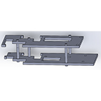
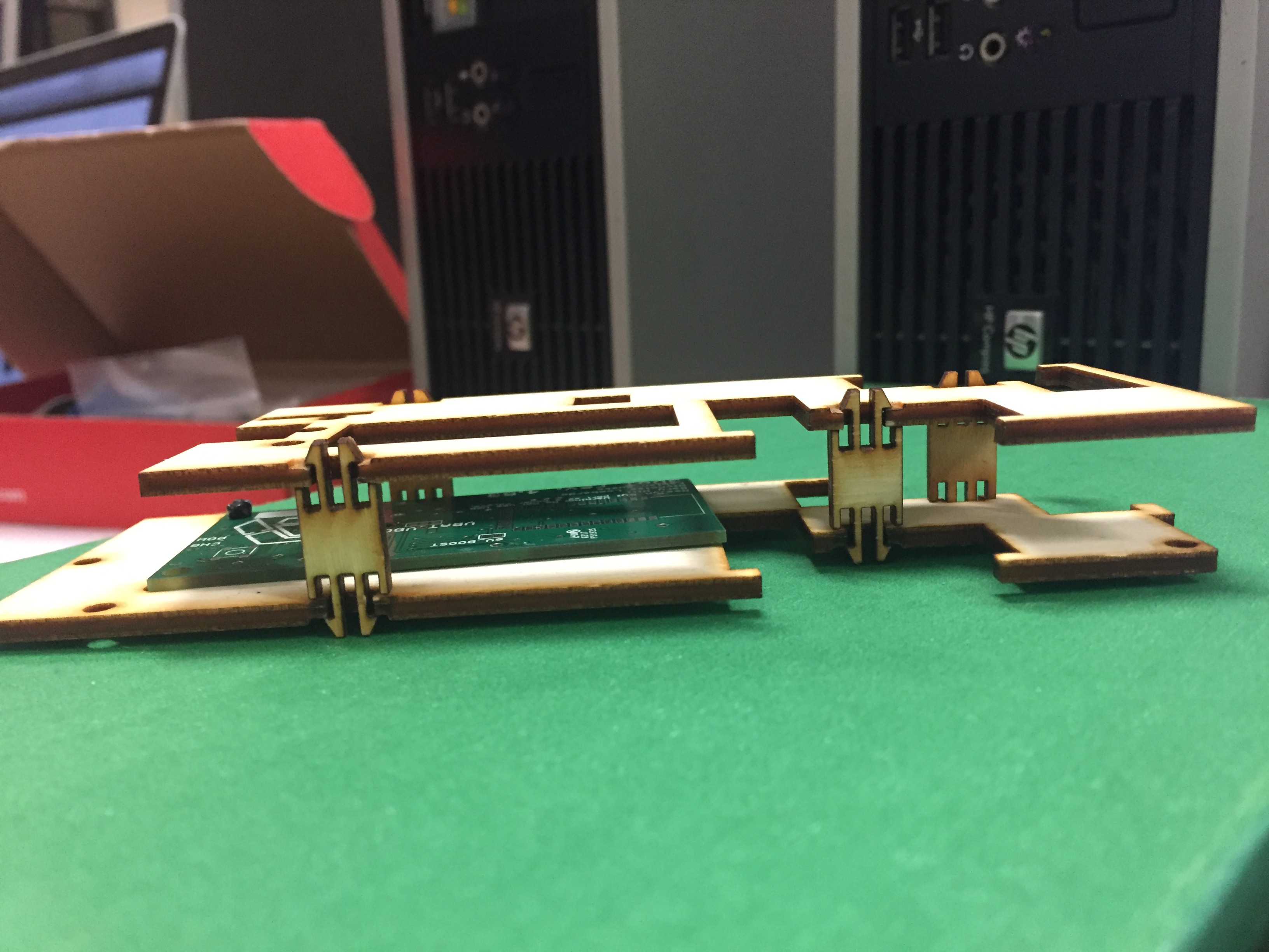
    After printing the first design, the customer asked to introduce another way to assemble the toy and suggested nut captures.  The first design uses the c-clamps, which have been successfully implemented in previous models.  The model shown below was assembled by Natalie, the Modwheels manufacturing engineer.

    Figure 1 – Initial design assembly


    Alternate assembly

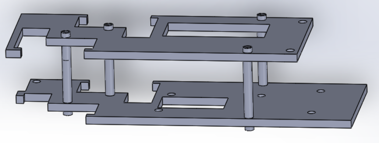
    Implementing the nut capture method requires a couple of design changes to the top and bottom panels. After researching different methods, I decided on a simple solution. The simple solution is to replace the squared cutouts for the clamps with circle cutouts. This may cause stress on the rest of the part. A second more detailed solution is explained in source 1. The latter requires an increase in thickness on both panels. For the spacers modeled below, Natalie suggested using nylon material.

    Figure 2 – Nut capture assembly (Solidworks)


    Figure 3 – Nut capture assembly


    Sources

    1. http://www.instructables.com/id/3D-Print-captured-nuts-without-pausing-your-print/
  • ModWheels 3DoT v 5.03 Integration and Test

    ModWheels 3DoT v 5.03 Integration and Test

    By: Lucas Gutierrez (Project Manager) & Matt Shellhammer (Electronics & Control Engineer)

    12/12/2017

    As of Tuesday, December 12th, 2017, ModWheels does not have an operational v. 5.03 3DoT.  ModWheels was given a v. 5.03 on Monday, December 11th, 2017 without a Bluetooth module (HM-11) or a battery holder.  After soldering the HM-11 and battery holder, a test was done and motors and peripheral subsystems encoders could not be powered simultaneously.  Due to this, along with the HM-11 being inoperable, ModWheels decided to revert back to the SparkFun ProMicro microcontroller for continued prototyping until 3DoT issues have been resolved.

    11/19/2017

    To fulfill the customer’s request, ModWheels will incorporate the 3DoT as its choice for a micro-controller.  As of 11/15/2017, the most recent EE 400D class, the 3DoT v 5.03 was available for in-class testing.  When the 3DoT v 5.03 becomes available for long term usage, a more thorough blog post will cover its the testing and integration with respect to the ModWheels project.

  • ModWheels Custom Command and Telemetry

    ModWheels Custom Command and Telemetry

    By: Lucas Gutierrez (Project Manager)


    Discussion

    An important aspect in fulfilling ModWheel’s mission requirements is integration with the Arxterra platform, both with the phone application and web based application.  To tailor and customize the user experience of the Arxterra applications to the ModWheels project, a few custom commands and telemetry will be incorporated. ModWheels would have implemented a 4 state custom command on the Arxterra GUI.  These states would have been RC (user controlled), Memory (Navigate with user), Replay (autonomous navigation), and Phase 2 (avoiding robots). RC mode would allow the user to control the ModWheels toy robot with the given slider options (motor). Memory would be a navigation of the maze with the user guiding the robot to the end of the maze. Replay would be the autonomous navigation of the maze based off Memory mode. Phase 2 would deal with avoiding robots in the maze. A new slider widget should be requested to allow for direct control of the servo on the ModWheel toy robot. The issues that arose revolving the 3DoT board made it difficult to test Arxterra on our toy robot.  Future teams that do decide to adopt this project should collaborate with Jeff Gomes when dealing with the Arxterra GUI.  Custom gadgets can be implemented that could make controlling the toy robot easier.

    Custom Commands

    RC Mode

    Inside the maze

    D-pad will be used to call predefined turn subroutines.

    Outside of the maze

    D-pad

    Forward: Increase speed from current speed to 255.

    Left: Move servo to left when pressed and move back to center when button is released.

    Right: Move servo to right when pressed and move back to center when button is released.

    Back: Decrease motor speed from current speed to 0.

    Autonomous Mode

    Make predefined turns based on recorded data.

    Telemetry

    • Battery level indicator.
    • Robot orientation (when using web based application).
    • Direction (when using web based application).
    • Current room (when using web based application).
  • ModWheels Power Budget

    ModWheels Power Budget

    By: Andrew Yi (Mission, Systems, & Test Engineer)
    Approved By: Lucas Gutierrez (Project Manager)

    Introduction

    The 3DoT Board is comprised of key components that each draw current from the battery.  The boost receives input from the battery directly, and in turn provides power to the LDO. The power report has been updated per the Division Manager and modified to each individual project.
    Figure 1: Power Budget
    Figure 2: Power Budget
    The test report for the GM-6 motors can be seen here:
    The test report for the servo can be seen here:
    2 color sensors and 2 shaft encoders are being used on our toy robot and the totals have been placed in the spreadsheet.  The motors and the servo will be pulling most of the current from our system, but the tests show us that they won’t impact the project’s power.
    Figure 3: Power Budget
    Figure 4: Power Budget
    The margins for the LDO, Boost, and battery allow for a large margin for additional components.  Power Budget 4.png shows the estimated battery run time of our toy robot.  With current components, the ModWheels robot has the power capabilities to accomplish the mission.
  • Calibration Of The Muse Laser Cutter

    Calibration Of The Muse Laser Cutter

    Written By: Lucas Gutierrez (Project Manager for ModWheels) & Charles Banuelos (Design & Manufacturing Division Manager)

    Worked On By: Charles Banuelos (Design & Manufacturing Division Manager) & Lucas Gutierrez (Project Manager for ModWheels)

    Calibration of The Muse Laser Cutter

    After configuring the laser cutter for power-up, calibration of the Muse laser cutter can begin.  Instructions on how to configure the laser cutter for power-up can be found in the post below.

    Configuring Laser Cutter for Power Up

    If properly configuring the laser cutter for power-up has not been performed yet, follow instructions on how to verify received components and additional materials needed for optimized use, which can be found in the post below.

    Muse Laser Cutter Parts Verification & Additional Purchase of Materials

    Steps on how to calibrate the Muse laser cutter can be found through the Muse Laser Calibration Guide video, as well as the Muse Laser Cutter manual.  Links for each can be found below.

    Muse Laser Cutter Manual

    This calibration consists of aligning each of the three mirrors to match the guide red guide laser to the power laser (used for cutting).  Below is a summary of the steps performed to calibrate the Muse Laser Cutter.

    1. Power on the Muse laser cutter and allow initial power on calibration to finish
    2. Place a small enough piece of thermal paper to cover mirror 1 (upper left corner of the laser bed)
    3. Fire a test laser pulse (controlled by the touch-screen)
    4. Check burn patter (made by the test laser pulse) against the red guide laser dot
    5. If off, adjust red guide laser to the burn patter using the included allen wrench (guide laser located towards the back of the laser bed)
    6. Once adjusted, remove thermal paper and place new piece of thermal paper onto the second mirror
    7. Move laser arm to the farthest positive (+) y direction (towards the back of the laser bed)
    8. Repeat steps 3-4
    9. If off, adjust the first mirror so that the red guide laser matches up with the burn pattern (skip this step if they match)
    10. Move laser arm to the farthest negative (-) y direction (towards the front of the laser bed)
    11. Repeat steps 3-4
    12. If the two burns do not match up, repeat step 9 (skip this step if they match)
    13. Once adjusted, remove thermal paper and place new piece of thermal paper onto the third mirror
    14. Move laser arm to the farthest negative (-) x direction (towards the left of the laser bed)
    15. Repeat steps 3-4
    16. If off, adjust second mirror so that the red guide laser matches up with the burn pattern (skip this step if they match)
    17. Move laser arm to the farthest positive (+) x direction (towards the right of the laser bed)
    18. Repeat steps 3-4
    19. If the two burns do not match up, repeat step 16  (skip this step if they match)
    20. Once adjusted, remove thermal paper and place new piece of thermal paper onto the lens on the laser arm
    21. Repeat steps 3-4
    22. If off, adjust third mirror so that the red guide laser matches up with the burn pattern (skip this step if they match)

    That concludes the initial calibration of the Muse laser cutter.


    Fall 2017:

    Calibration Method

    After an initial configuration of the system, on Friday (11/03/2017) at 1 pm, a calibration of the laser cutter was completed.

    This calibration consisted of aligning each of the three mirrors to match the guide red guide laser to the power laser (used for cutting).

    The calibration was done by placing thermal paper onto the first mirror, firing a test burn, then confirming or realigning the red guide laser to the burn spot. This process was repeated for the extremes of the placement of the laser on the relative axis. This was performed on each mirror and was confirmed by a test cut.