[av_textblock size=” font_color=” color=” av-medium-font-size=” av-small-font-size=” av-mini-font-size=” admin_preview_bg=”]
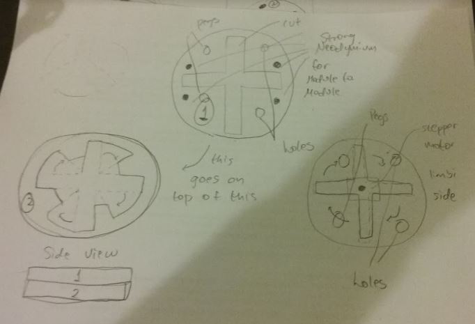
For the module-to-module docking, our team have decided to use permanent magnets; specifically, neodymium magnet discs for symmetry. So, how strong should the magnets be?
Well, we want it just strong enough for the two modules to securely dock; if it is too strong, then it might reposition the idle servo (joints of the arm) during module-to-module docking.
[/av_textblock]
[av_heading tag=’h1′ padding=’10’ heading=’Magnet Test’ color=” style=” custom_font=” size=” subheading_active=” subheading_size=’15’ custom_class=” admin_preview_bg=” av-desktop-hide=” av-medium-hide=” av-small-hide=” av-mini-hide=” av-medium-font-size-title=” av-small-font-size-title=” av-mini-font-size-title=” av-medium-font-size=” av-small-font-size=” av-mini-font-size=”]
Stuff we will put here woohoo…
[/av_heading]
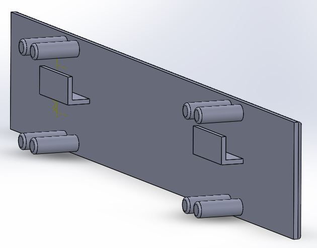
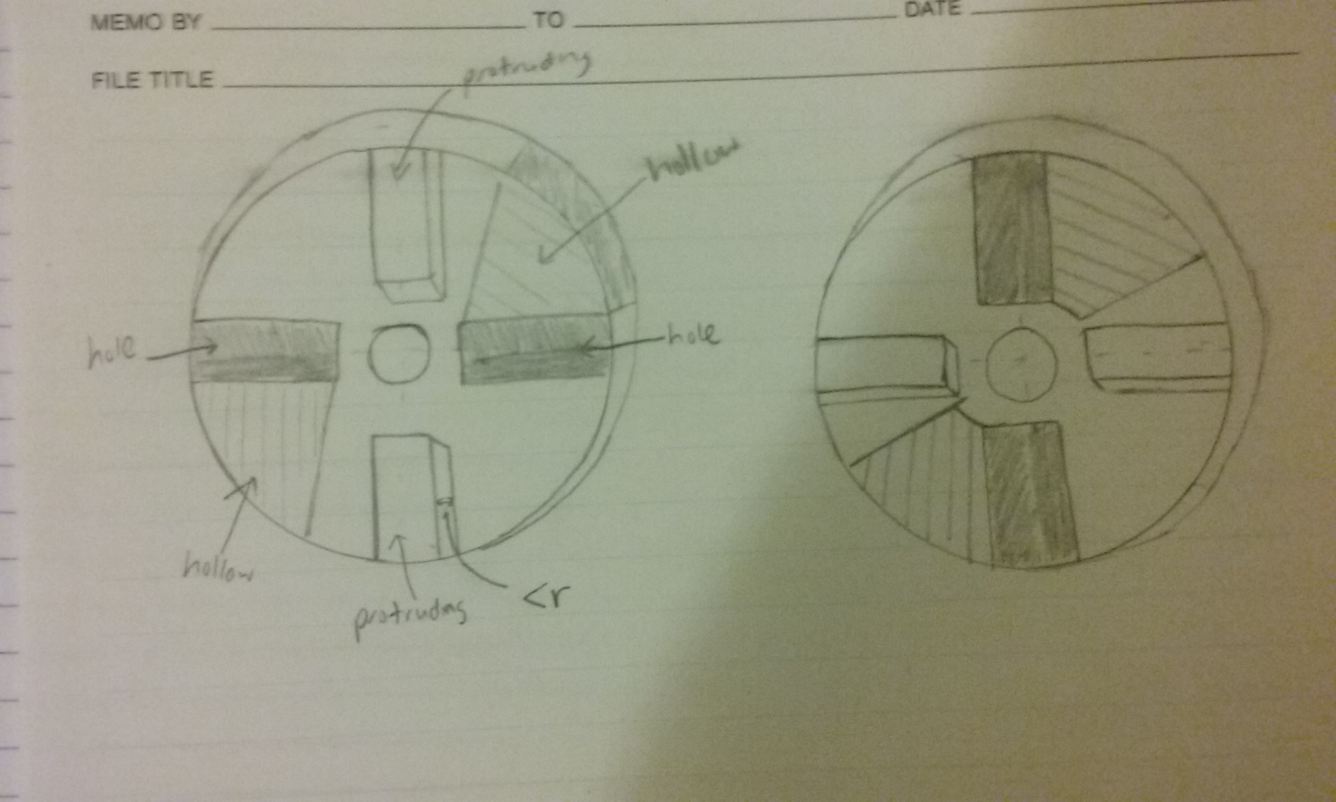
Cross sectional view of module showing the permanent magnet placement.
This is the design that our D&M team came up with. For the module-t0-module docking, there will be about 0.05 inches (x2) = 0.1 inches of material between magnet pairs.
Our team experimented with 5 magnet pairs with 5 different pull forces: 1.7 lbs, 5.2 lbs, 9.5 lbs, 10 lbs, 15 lbs.
*Pull force is the amount of force needed to detach a magnet away from a flat surface.
Our team found that pull forces greater than 5 lbs are too strong and caused idle servos to turn during docking. On the other hand, the 1.7 lb pull force magnets are just the strength for our application.
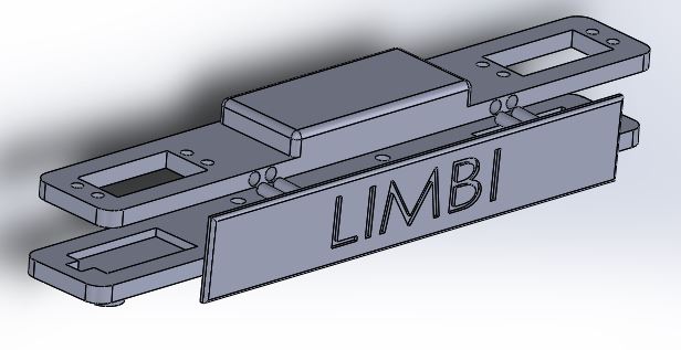
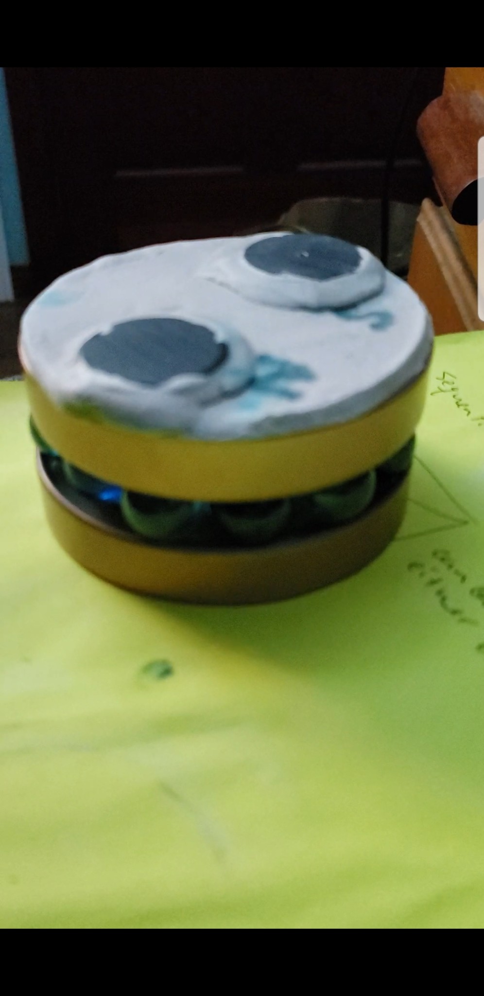
Limbi Magnet Test for 1.7 lb magnetic pull force for the module-to-module docking. 4 Magnets holding two parts together with about 0.1 inches of PLA plastic in between.
[av_textblock size=” font_color=” color=” av-medium-font-size=” av-small-font-size=” av-mini-font-size=” admin_preview_bg=”] The reason why we chose magnet discs (instead of magnet strips/magnet blocks/non magnetic mechanism) is because of its symmetry for easy placement and it does not require power. We want to be able to implement the module-to-module docking design in the arm-to-module docking. We currently have our requirement (2.1.15.1) as two separate docking faces for module-to-module and arm-to-module for the module design but we later aim to have a universal (the same module-to-module and arm-to-module) connection later in the design process.
[av_textblock size=” font_color=” color=” av-medium-font-size=” av-small-font-size=” av-mini-font-size=” admin_preview_bg=”] There are three main mechanical assembly for Limbi: Arm, Docking mechanism, and the module. Rapid prototyping lead to several critical design changes. The following are the main design changes made:
(Note: all images provided are the final design iteration)
[/av_textblock]
[av_heading tag=’h1′ padding=’10’ heading=’Arm Design’ color=” style=” custom_font=” size=” subheading_active=” subheading_size=’15’ custom_class=” admin_preview_bg=” av-desktop-hide=” av-medium-hide=” av-small-hide=” av-mini-hide=” av-medium-font-size-title=” av-small-font-size-title=” av-mini-font-size-title=” av-medium-font-size=” av-small-font-size=” av-mini-font-size=”]
Stuff we will put here woohoo…
[/av_heading]
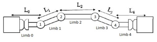
The Limbi Arm is comprise of 5 Limbs: L0, L1, L2, L3, L4. This 400D Limbi version is a scaled down (1/2) version of JPL’s Limbi. The dimensions are taken directly from JPL’s LIMBI IEEE paper. The design however is a product of functionality and simplicity.
Each limb has two layers (top and bottom) to hold the servos in place, a brace on each side to put the two layers together as a limb and servo mount holes/cuts/grooves. Limb 1, Limb 2 and Limb 3 bottom layer has swivels to act as joint 1, 2, 3 and 4.
There are 10 main design iteration for the arm design:
Press fit extrusion and hole pairs for the brace and limb layers to reduce amount of screws and for easier assembly.
Tolerances and placements for the servo/ joints/ adjacent limbs mounts holes/grooves/cuts/extrusions for snug fits, cosmetics and even arm design.
Space for the electronics in the middle of limb 2 (extruded rectangle in the middle).
Extrusion in the bottom layer of L1 and L3 for an even ball caster height and easier installation (vs long threaded screw to adjust height previously).
Incorporation of swivels (joints) in the bottom layer of L2, L1 and L3 to have it as one whole piece (vs a different component previously)
Removal of Circular stands with extruded domes (for small contact points) from L1 and L3 (replaced with ball casters instead).
Two smaller casters in L1 and L3 (four total) to keep the arm standing for every possible position (vs 1 big one for each causing the limb to roll in a very unstable fashion).
Lengths of the Limbs:
L0, L1, L3, L4: easier inverse kinematics (ratio for the lengths of L0 and L1 is a critical part of inverse kinematics).
L2: limited range of actuators used (servos) caused a problem performing phase 2 of mission objective.
Added hooks on the inside of the brackets for cable routing.
Lengths of braces to cover inside as much as possible while accommodating the range of motion for joints 1, 2, 3, 4.
Notes:
The length of the limbs are not measured from tip to tip of the mechanical assembly but rather the distance between two adjacent servo gears (joint to joint).
It is later discovered that the limited range of the actuators used (servos) caused problems with arm motion therefore requirement is later change to form factor of JPL’s Limbi (see iteration #8).
[av_textblock size=” font_color=” color=” av-medium-font-size=” av-small-font-size=” av-mini-font-size=” admin_preview_bg=”]
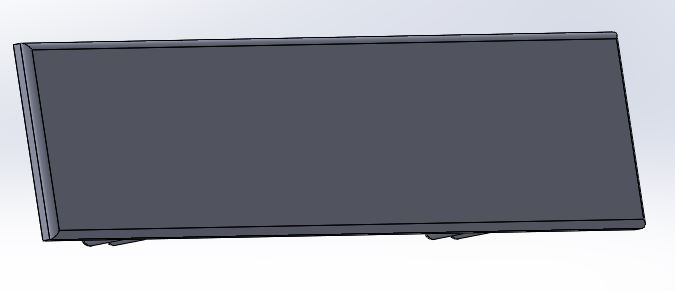
Dimensions: 10 in x 1.50 in x 0.25 in
Front View of L2: Top is the top layer and bottom is the bottom layerUnderside view showing swivel on the bottom layer
[av_textblock size=” font_color=” color=” av-medium-font-size=” av-small-font-size=” av-mini-font-size=” admin_preview_bg=”]
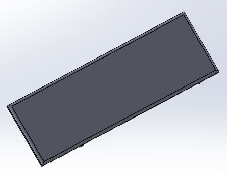
Dimensions: 7.5 in x 1.5 in x 0.25 in
Front View of L1 and L3: Top is the top layer and bottom is the bottom layerUnderside view showing swivel, servo and caster mount on the bottom layer
[av_textblock size=” font_color=” color=” av-medium-font-size=” av-small-font-size=” av-mini-font-size=” admin_preview_bg=”]
Dimensions: 4 in x 1.5 in x 0.25 in
Front View of L0 and L4: Top is the top layer and bottom is the bottom layerUnderside view showing servo mounts for the joint and docking servo
[av_textblock size=” font_color=” color=” av-medium-font-size=” av-small-font-size=” av-mini-font-size=” admin_preview_bg=”]
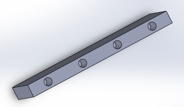
Dimensions of the long braces: 7.5 in x .25 in x 0.10 in
Dimensions of the short braces: 3.75 in x .25 in x 0.10 in
Inside view of L2 brace showing extruded parts for press fit and cable routingOutside view of L2 braceOutside view of L1 and L3 brace
[av_textblock size=” font_color=” color=” av-medium-font-size=” av-small-font-size=” av-mini-font-size=” admin_preview_bg=”] The Docking Mechanism is the main design innovation of Limbi.
There are two main design challenge for the docking mechanism:
Momentum less docking and undocking
Power transfer interface
There are 10 main design iteration for the docking design:
Placement of modular contacts (for the power transfer) in docking layer 1 (which itself had few iterations).
Tolerances for the docking layer 2 (bigger slot).
Press fit extrusion and hole pair for docking layer 1 and docking layer 2.
Dimensions of the cross.
Housing in one of the cross branch for the push-pull solenoid valve for the positive lock.
Grooves/cuts in cross for conductive tip design (for power transfer) and cable routing.
Servo Coupler integrated in the cross (vs a separate component previously).
Higher walls for the docking layer 1 for smoother turn for the cross when engaging (cross will get caught during turn if tolerance is too tight).
Tolerance for the holes for the Solenoid Valve autolock of docking layer 1.
Snug fit Housing for the modular contacts of docking layer 1 and the cut where the wires run through.
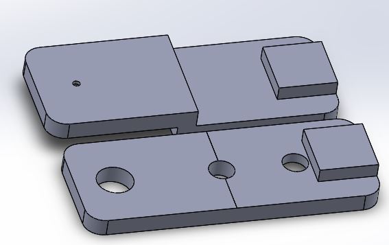
[av_textblock size=” font_color=” color=” av-medium-font-size=” av-small-font-size=” av-mini-font-size=” admin_preview_bg=”]
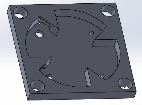
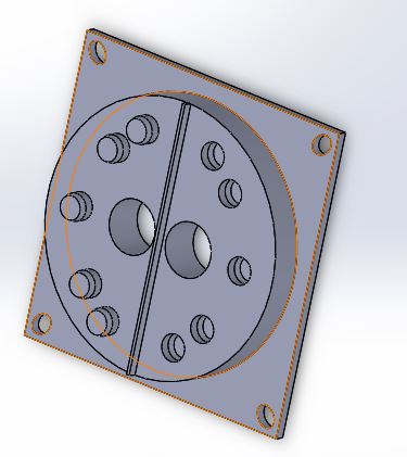
Dimensions: 4 in x 4 in x 0.4 in
1st layer of docking design showing cuts for modular contacts, holes for the cable routing, holes for the docking layer 2 press fit, and hole for the solenoid valve auto lock.
[av_textblock size=” font_color=” color=” av-medium-font-size=” av-small-font-size=” av-mini-font-size=” admin_preview_bg=”]
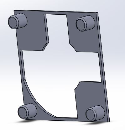
Dimensions: 4 in x 4 in x 0.20 in
2nd layer of docking design showing the extruded part for the press fit
[av_textblock size=” font_color=” color=” av-medium-font-size=” av-small-font-size=” av-mini-font-size=” admin_preview_bg=”]
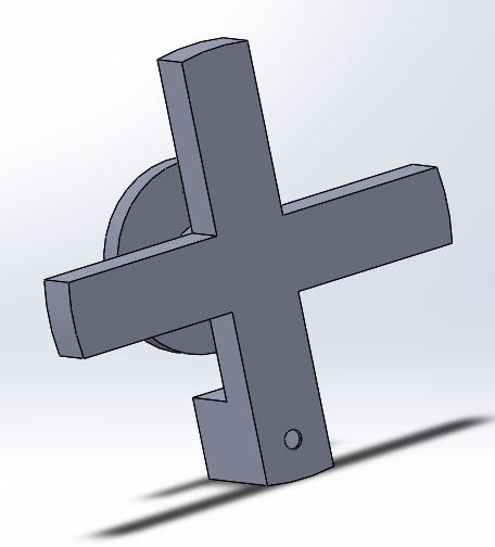
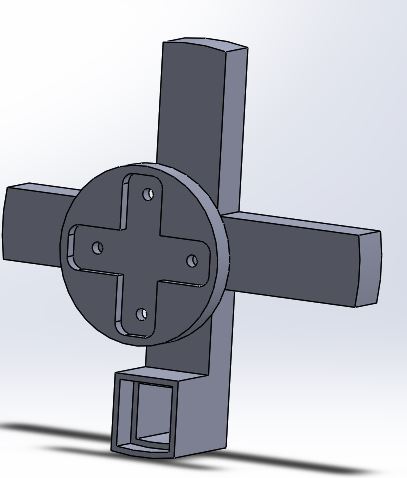
Dimensions (from tip to tip): 3.4 in x 3.4 in x 0.36 in (length of each branch is 0.60 in)
Front view of the Cross showing the hole for the push-pull solenoid valve peg for the lockBack view of the cross showing the integrated servo coupler and the push-pull solenoid valve housing
[av_textblock size=” font_color=” color=” av-medium-font-size=” av-small-font-size=” av-mini-font-size=” admin_preview_bg=”] The module design is the simplest part of Limbi. Design is based on the final docking mechanism design (for the cable routing and fittings), permanent magnet placement for module-to-module design and the LiPo battery placement. Dimensions (4x4x4 inches) are 1/2 of JPL’s Limbi module (8x8x8 inches).
Three faces of the module have special features: One face to mount LiPo battery, another face to mount permanent magnets for module-to-module connection and one open face for the docking layer for arm-to-module connection.
There are 4 main design iteration for the module design:
Magnet placement hiding the magnets behind the walls so outside faces are flat (vs expose permanent magnets previously).
Housing for the LiPo Battery.
Cut for the charging port for the battery.
Bracket at the opposite side of the arm-to-module face to secure position of module 1 as part of the requirement.
[/av_textblock]
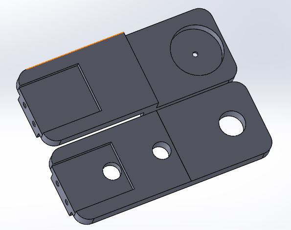
[av_textblock size=” font_color=” color=” av-medium-font-size=” av-small-font-size=” av-mini-font-size=” admin_preview_bg=”]
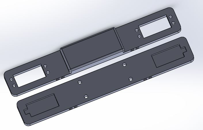
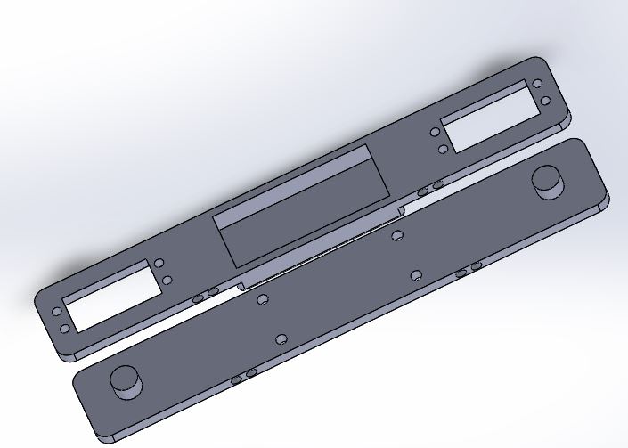
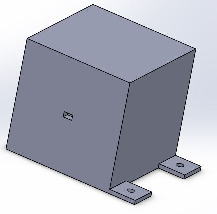
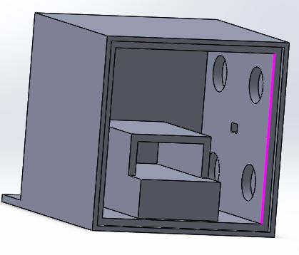
Dimensions: 4in x 4 in x 4 in (not including the bracket)
Isometric View 1 showing the bracket to secure module position and charging port for the LiPo Battery.Isometric View 2 showing the face for the docking face, LiPo Housing, and circular cuts for magnets.
[av_textblock size=” font_color=” color=” av-medium-font-size=” av-small-font-size=” av-mini-font-size=” admin_preview_bg=”] Rapid Prototyping helped Limbi team tremendously. We are able to see design flaws early in the design process.
The reason why we are able to rapid prototype this much is because I have my own printer. We are able to print ideas, fix design flaws and test fittings anytime we want without the worry of paying for a costly 3D print service.
Side note: I personally recommend buying your own 3D printer. It is a great investment. I recommend Creality Ender-3 as a starting point (Banggood usually has the cheapest deal for this printer).
[/av_textblock]
[av_textblock size=” font_color=” color=” av-medium-font-size=” av-small-font-size=” av-mini-font-size=” admin_preview_bg=”]
To reduce the use of adhesive and hardware such as nuts, bolts, screws and washers, our D&M team decided to implement the idea of press fitting in our assembly. Press fit is a mechanical fastening between two parts which is achieved by friction after the parts pushed together.
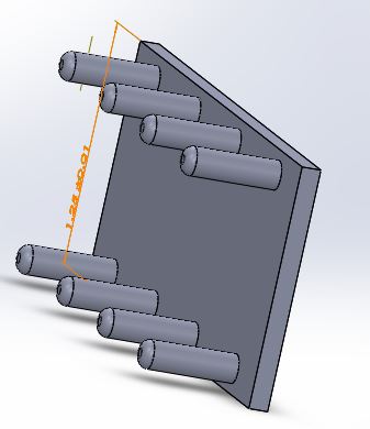
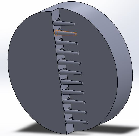
Limbi’s D&M team designed and printed test prototype for our press fit parts to be used in our brace design and docking mechanism layers.
Male side test print for press fit design.Female side test print for press fit design.
We tested three different extrude and hole pairs:
*length of extrusion and cut are the same: 0.5 inches
0.15 in diameter extrusion and 0.16 in diameter cut (0.01 inch difference in diameter).
0.15 in diameter extrusion and 0.175 in diameter cut (0.025 inch difference in diameter).
0.15 in diameter extrusion and 0.2 in diameter cut (0.05 inch difference in diameter).
Results:
-0.01 in difference is too tight extruded parts would not even fit in the holes.
For he two other extrusion and cut pairs, gravity test is performed: mated parts are held upside down where the friction is the only force holding the male part.
-0.05 in difference is loose which cause the part to fall off.
-0.025 in difference is just the right fit that held the male part from falling during the gravity test. Also, it still allows for the pair to detach.
[/av_textblock]
[av_heading tag=’h1′ padding=’10’ heading=’Implementation to the Limbi Design’ color=” style=” custom_font=” size=” subheading_active=” subheading_size=’15’ custom_class=” admin_preview_bg=” av-desktop-hide=” av-medium-hide=” av-small-hide=” av-mini-hide=” av-medium-font-size-title=” av-small-font-size-title=” av-mini-font-size-title=” av-medium-font-size=” av-small-font-size=” av-mini-font-size=”]
Stuff we will put here woohoo…
[/av_heading]
[av_textblock size=” font_color=” color=” av-medium-font-size=” av-small-font-size=” av-mini-font-size=” admin_preview_bg=”]
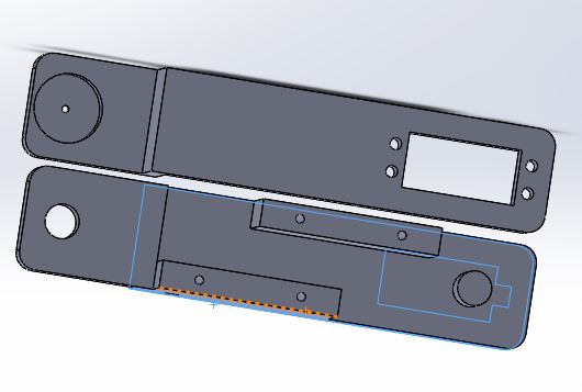
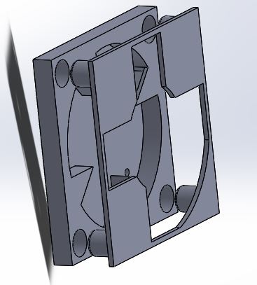
We used press fittings in two subassemblies: the two layer for our docking mechanism and the arm braces.
Exploded view of the two layers of the docking mechanism assembly showing the implementation of the press fit design.Exploded view of L2 assembly showing the implementation of the press fit design of the side brace.
[av_heading tag=’h1′ padding=’10’ heading=’Abstract’ color=” style=” custom_font=” size=” subheading_active=” subheading_size=’15’ custom_class=” admin_preview_bg=” av-desktop-hide=” av-medium-hide=” av-small-hide=” av-mini-hide=” av-medium-font-size-title=” av-small-font-size-title=” av-mini-font-size-title=” av-medium-font-size=” av-small-font-size=” av-mini-font-size=”]
Stuff we will put here woohoo…
[/av_heading]
[av_textblock size=” font_color=” color=” av-medium-font-size=” av-small-font-size=” av-mini-font-size=” admin_preview_bg=”]
Limbi Team’s main design innovation is to design a low-power momentumless androgynous (universal) docking mechanism that can transfer power. Since we are demonstrating an in-space assembly, we need our docking mechanism to be momentumless (no pushing force) but at the same time be capable of transferring power and/or signal through the connections. Once dock, a low-power positive lock should keep the two docking face together while moving.
Before PDR, our team had our own creativity exercise (Dunker Diagram, Brainstorming, Attribute Listing, Lateral Thinking) where we present our idea’s to each other. Each has its own failure points that failed conceptual operation (ConOps) one way or the other. Androgynous design #6 is the closest to the final design idea for Limbi generation#1 (though it should be mention that a feature or two from each design is an inspiration for the final design). The following are the ideas each member of the team came up with: