[av_one_full first min_height=” vertical_alignment=” space=” custom_margin=” margin=’0px’ padding=’0px’ border=” border_color=” radius=’0px’ background_color=” src=” background_position=’top left’ background_repeat=’no-repeat’ animation=”]
[av_textblock size=’35’ font_color=” color=” av-medium-font-size=” av-small-font-size=” av-mini-font-size=” admin_preview_bg=”]
Proposal Bot/Spring/2020
[/av_textblock]
[av_hr class=’default’ height=’50’ shadow=’no-shadow’ position=’center’ custom_border=’av-border-thin’ custom_width=’50px’ custom_border_color=” custom_margin_top=’30px’ custom_margin_bottom=’30px’ icon_select=’yes’ custom_icon_color=” icon=’ue808′ font=’entypo-fontello’ admin_preview_bg=”]
[av_textblock size=’30’ font_color=’custom’ color=” av-medium-font-size=” av-small-font-size=” av-mini-font-size=” admin_preview_bg=”]
Buck Converter Analysis
[/av_textblock]
[av_textblock size=” font_color=’custom’ color=’#bfbfbf’ av-medium-font-size=” av-small-font-size=” av-mini-font-size=” admin_preview_bg=”]
Author: Ethan Thiessa
[/av_textblock]
[av_hr class=’short’ height=’50’ shadow=’no-shadow’ position=’left’ custom_border=’av-border-thin’ custom_width=’50px’ custom_border_color=” custom_margin_top=’30px’ custom_margin_bottom=’30px’ icon_select=’yes’ custom_icon_color=” icon=’ue808′ font=’entypo-fontello’ admin_preview_bg=”]
[av_textblock size=” font_color=” color=”]
[/av_textblock]
[av_heading tag=’h1′ padding=’10’ heading=’Introduction ‘ color=” style=” custom_font=” size=” subheading_active=” subheading_size=’15’ custom_class=” admin_preview_bg=” av-desktop-hide=” av-medium-hide=” av-small-hide=” av-mini-hide=” av-medium-font-size-title=” av-small-font-size-title=” av-mini-font-size-title=” av-medium-font-size=” av-small-font-size=” av-mini-font-size=”][/av_heading]
[av_textblock size=” font_color=” color=” av-medium-font-size=” av-small-font-size=” av-mini-font-size=” admin_preview_bg=”]
To operate our buck converter, I chose an LM2596 simple switcher 3A step down voltage regulator where the datasheet can be found here. The LM2596 can take input voltages up to 40V and output voltages down to 1.2V – 37V with a 3A output load current. The LM2596 can be used in four configurations with an output of 3.3V, 5V, 12V, and adjustable voltage output.
[/av_textblock]
[av_heading tag=’h1′ padding=’10’ heading=’Electrical Characteristics of LM2596′ color=” style=” custom_font=” size=” subheading_active=” subheading_size=’15’ custom_class=” admin_preview_bg=” av-desktop-hide=” av-medium-hide=” av-small-hide=” av-mini-hide=” av-medium-font-size-title=” av-small-font-size-title=” av-mini-font-size-title=” av-medium-font-size=” av-small-font-size=” av-mini-font-size=”]
Stuff we will put here woohoo…
[/av_heading]
[av_textblock size=” font_color=” color=” av-medium-font-size=” av-small-font-size=” av-mini-font-size=” admin_preview_bg=”]

As seen from the datasheet above, using the adjustable voltage version of the LM2596, they were able to get a typical 73% power efficiency when the input was 12V and the output was 3V with a 3A load current. The efficiency and performance of the voltage regulator are affected by the external components used such as the diode rectifier, inductor, and input and output capacitors, which makes choosing the external components crucial to a well-performing voltage regulator.
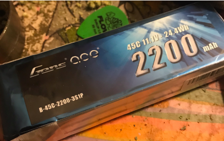
For our project we are using an 11.1V lithium-ion battery to provide enough current to power the 4 stepper motors for the wheels that need a minimum of 8.5V and approximately 600mA- 1000mA to run. The battery we are using is rated at 3S 2200mAh 45C, so the theoretical max current draw is 2200mA * 45C = 99A. This is more than enough current to power our four stepper motors and two servos for the actuation of the ring box and pen plotter.
[/av_textblock]
[av_heading tag=’h2′ padding=’10’ heading=’Buck Converter Design’ color=” style=’blockquote modern-quote’ custom_font=” size=” subheading_active=” subheading_size=’15’ custom_class=” admin_preview_bg=” av-desktop-hide=” av-medium-hide=” av-small-hide=” av-mini-hide=” av-medium-font-size-title=” av-small-font-size-title=” av-mini-font-size-title=” av-medium-font-size=” av-small-font-size=” av-mini-font-size=”][/av_heading]
[av_textblock size=” font_color=” color=” av-medium-font-size=” av-small-font-size=” av-mini-font-size=” admin_preview_bg=”]
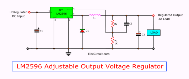
The circuit configuration for the LM2596 that was used for the Proposal Bot PCB was found on ElecCircuit.com. In this configuration of the buck converter, we have three different capacitors, a diode, an inductor, and two resistors forming a voltage divider.
Input and Output Filter Capacitors (C1 and C2)
The input filter capacitor (C1) is used on the power rails of the input of the LM2596, in order to lower the voltage transients going into the voltage regulator along with supplying the switching currents required by the regulator. We are using a fairly large 470uF electrolytic capacitor to filter out unwanted frequencies from our lithium battery power supply. This capacitor is also responsible for eliminating glitch power, which can dissipate 20%-70% of the total power. Removal of these glitches will allow the regulator to have steady switching activity.
The output filter capacitor (C2) is used on the power rails of the output of the LM2596. This capacitor is used to further smooth out the DC voltage on the output of the voltage regulator in order to get a steady output voltage. For our project, we are using a 220uF electrolytic capacitor in order to achieve a steady output voltage for our servo motors.
Feedforward Capacitor (C3)
The C3 capacitor is used as a feedforward capacitor which is placed across the high-side feedback resistor. This feedforward capacitor adds an extra pole and zero to the control loop, which can improve the phase margin and bandwidth of the regulator circuit. This is a commonly used method to improve the stability and bandwidth of a power supply to obtain a more efficient control system. For our project, we are using a 3.3nF ceramic capacitor to achieve a more stable system.
Shottky Rectifier Diode (D1)
The D1 Schottky rectifier diode is placed along the output of the LM2596 and the ground rail of the buck converter. The diode is going to act as a catch diode for the LM2596. With the maximum current rating being 1.2 times greater than the max load current, it should be able to withstand a continuous output short. The reverse voltage of the diode should be at least 1.25 times the maximum input voltage. For our design, we used an SBR1045 super barrier diode which has a max current rating of 10A and a max reverse voltage of 32V. This is more than enough for our design to power our motors and keep the LM2596 running efficiently.
Calculations
Design:
Max Current Draw: 1.2A
Max Voltage: 11.1V
Diode Characteristics Needed:
Max Current Rating: 1.2*1.2A = 1.44A
Max Reverse Voltage: 1.25*11.1V = 13.88V
SBR1045 Diode:
Max Current Rating: 10A
Max Reverse Voltage: 32V
Inductor (L1)
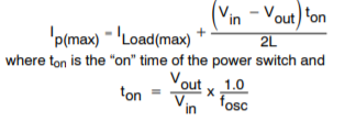
The inductor for this design is placed on the ouput of the LM2596 to help with energy conversion for the linear regulator. There is a couple of equations used to help us pick the best Inductor for our design. The first equation below is used to calculate the inductor Volt x Microsecond [V x µs} constant.![]()
Then to calculate the inductance needed we can rearrange the equation below knowing that the current rating we want for our inductor needs to be 1.15 * ILoad.
As seen from the calculation above, the optimum inductance for our design is 82uH. We decided to go with a 68uH inductor, as they are more prevalent and it still fulfills the requirements of our design.
Voltage Divider Resistors (R1 and R2)
The two resistors on the output of the LM2596 are used to program the output voltage on the LM2596.
The equation to choose the correct resistor pair is shown above, where Vref = 1.23V is the minimum output voltage of the LM2596. From the LM2596 datasheet, R1 should be chosen to be between 1k ohms and 5k ohms. After choosing R1, you can use the equation below to calculate the resistance needed to obtain your desired output voltage for the buck converter.
![]()
For our design, we needed a 6V output for our Buck converter to power our servo motors. To obtain this output voltage we would use the equation above to calculate R2. Using this equation and choosing 5k ohms for R1 we obtain R2 = 5k*(6V/1.23V – 1.0) = 19,390 ohms. Since a resistor with that ohm rating is hard to obtain we used R2 = 20k ohms to obtain the desired output.
Using these two resistors the theoretical output for our buck converter should be
This output is within 0.2V of our desired output voltage, so we can accept the output.
[/av_textblock]
[av_heading tag=’h1′ padding=’10’ heading=’Measured Input/Output Voltages on PCB’ color=” style=” custom_font=” size=” subheading_active=” subheading_size=’15’ custom_class=” admin_preview_bg=” av-desktop-hide=” av-medium-hide=” av-small-hide=” av-mini-hide=” av-medium-font-size-title=” av-small-font-size-title=” av-mini-font-size-title=” av-medium-font-size=” av-small-font-size=” av-mini-font-size=”][/av_heading]
[av_textblock size=” font_color=” color=” av-medium-font-size=” av-small-font-size=” av-mini-font-size=” admin_preview_bg=”]
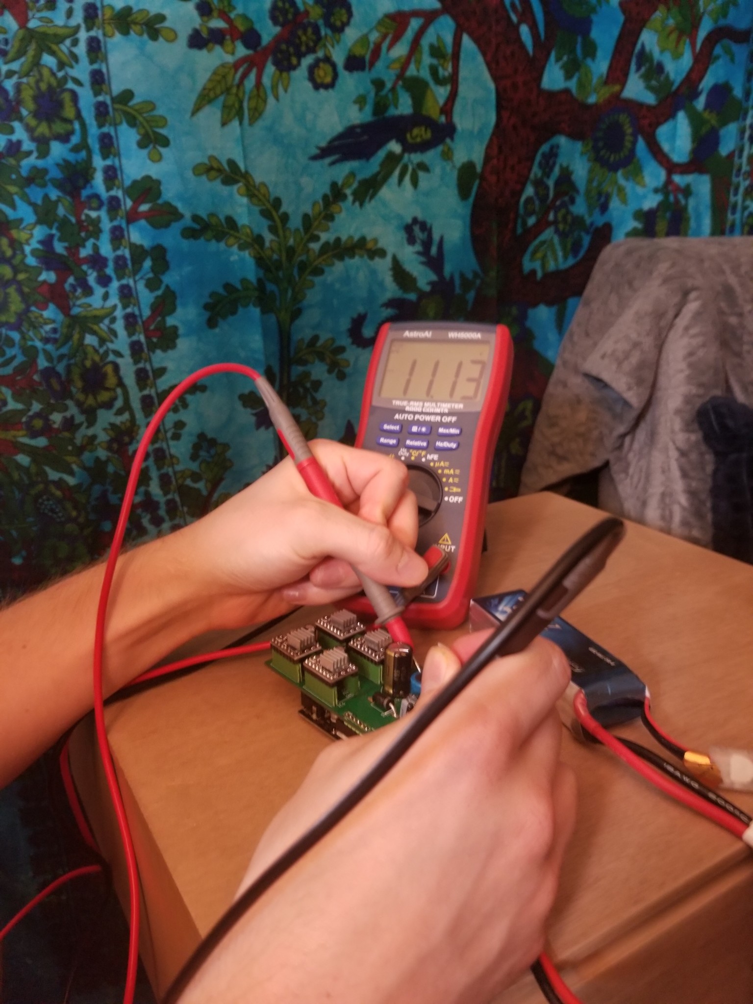
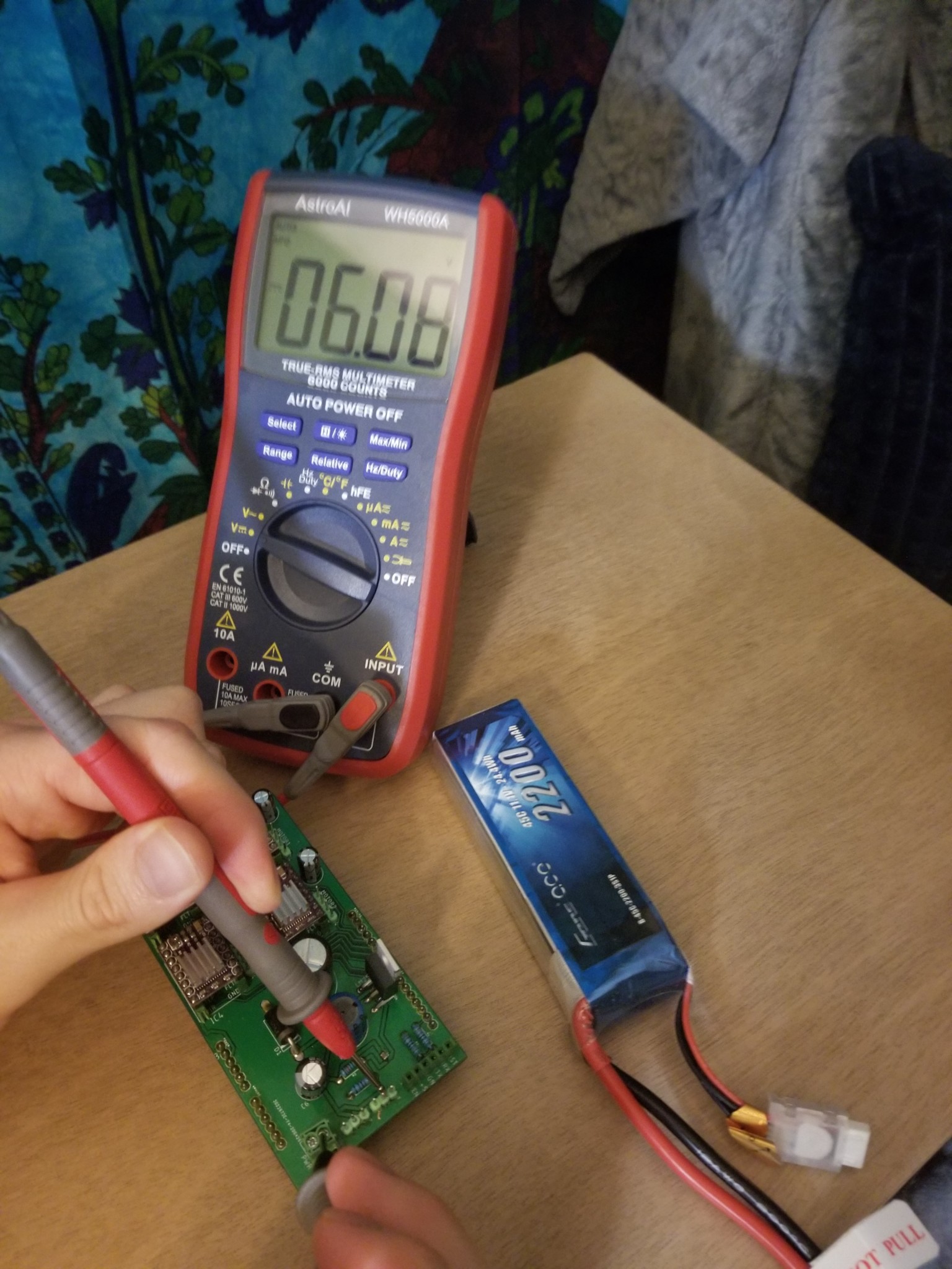
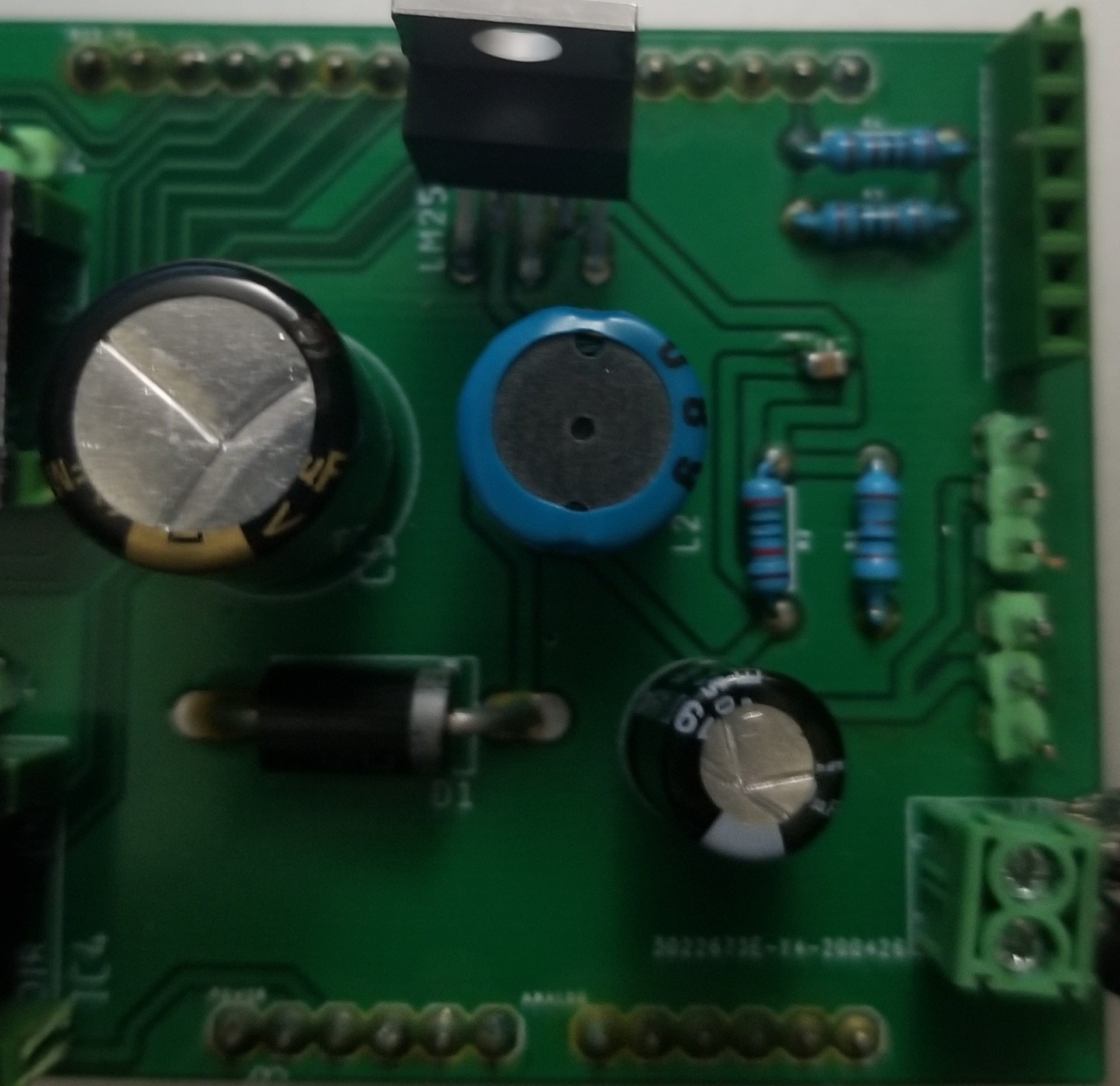
As seen from the figures above, the measured input voltage going into the LM2596 measured to be 11.13V, 30mV higher than the normal voltage, and the output measured to be 6.08V which is 70mV lower than the theoretical output voltage. This output works in our favor as it is now closer to 6V, but deviates slightly from the theoretical output voltage.
[/av_textblock]
[av_heading tag=’h1′ padding=’10’ heading=’Conclusion’ color=” style=” custom_font=” size=” subheading_active=” subheading_size=’15’ custom_class=” admin_preview_bg=” av-desktop-hide=” av-medium-hide=” av-small-hide=” av-mini-hide=” av-medium-font-size-title=” av-small-font-size-title=” av-mini-font-size-title=” av-medium-font-size=” av-small-font-size=” av-mini-font-size=”][/av_heading]
[av_textblock size=” font_color=” color=” av-medium-font-size=” av-small-font-size=” av-mini-font-size=” admin_preview_bg=”]
In conclusion, with the components chosen for this buck converter configuration, we were able to obtain an output voltage that is within 100mV of our desired output voltage to power our servo motors. For future reference, an output voltage of 5.5V would be more desirable for powering servos, since it gives you a better range of servos you can use for your project. With the 6V configuration, you are limited to using bigger servo motors that can handle 6V, since most small servo motors have a max rating of 6V. A variable resistor for R2 would’ve been a better design for this buck converter configuration, allowing the user to adjust the output voltage to fit the parameters of their requirements.
[/av_textblock]
[av_heading tag=’h1′ padding=’10’ heading=’References/Resources’ color=” style=” custom_font=” size=” subheading_active=” subheading_size=’15’ custom_class=” admin_preview_bg=” av-desktop-hide=” av-medium-hide=” av-small-hide=” av-mini-hide=” av-medium-font-size-title=” av-small-font-size-title=” av-mini-font-size-title=” av-medium-font-size=” av-small-font-size=” av-mini-font-size=”][/av_heading]
[av_textblock size=” font_color=” color=” av-medium-font-size=” av-small-font-size=” av-mini-font-size=” admin_preview_bg=”]
- https://www.onsemi.com/pub/Collateral/LM2596-D.PDF
- https://www.eleccircuit.com/regulator-switching-dc-to-dc-step-down-voltage-with-lm2596/
[/av_textblock]
[/av_one_full]
