[av_textblock size=” font_color=” color=” av-medium-font-size=” av-small-font-size=” av-mini-font-size=” admin_preview_bg=”] This Bonus Section of Lab 6 is here to help you gain back points that you may have lost in previous labs. If you already have a nearly perfect lab score, then I would recommend you skip this Bonus Lab since your lab grade cannot go over 100%.
This Bonus Lab includes four (4) bonus sections to help you win back points.
Table of Contents
Turning Corners (1 point)
Modify isHallway to not only return true if the bear is in a hallway, but also if the bear is in a corner room. Specifically, the bear must turn left (0011, 1100), or right (0101, 1010). When completed the bear should now not only walk down hallways but turn corners. The bear should still stop walking when a decision needs to be made or a room has bees.
Light Show (1 to 2 points)
Have your 8 LEDs put on a light show. For example a Night Rider scanner (1 point) or a random Blinking Light Unit (BLU). See the ShiftOut16.ino program for an example of a nice light show.
Congratulatory Tune (3 to 8 points)
In this bonus part of the Lab you are going to add a fun twist to the maze by teaching your program how to play a congratulatory song snip-it (ta-da) when the bear enters the forest and how to play a sad tune when he is lost in the maze (needs to turn around).
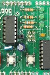
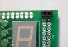
The arduino-proto-shield schematic found in the reference folder includes a simple speaker circuit for you to build. To connect your speaker to the Q output of the D flip-flop, solder a 1×1 .100mm female connector to JP16 as shown here.
To provide power (+5 v) to your speaker circuit, solder a 1×2 .100mm female connector to the first row of pins on the JP9 connector as shown here.
Please ask me if you have any questions.
In order to control the pitch and duration of each note you will need to use two timers. Do not forget that the D-flip-flop will divide your output frequency by a factor of 2. You may not duplicate a song snip-it done by another student or group. See me if you are not sure and most of all have fun.
The number of points awarded will be based on the number of milestones completed successfully. Here is my list of milestones that you may want to achieve and simply stop when you run out of time.
Congratulatory tone (single note) sounds when the bear enters the forest.
Congratulatory song snip-it (ta-da) plays when the bear enters the forest.
Sad tune plays when the bear is lost.
Congratulatory song plays when bear enters the room corresponding to your target square.
Congratulatory song plays (for example the theme from Star Wars) when bear leaves the maze and enters the forest.
a. Have the bear make snoring sounds before finally putting the microcontroller to sleep.
Write Your Own Bonus Code
Be creative and earn even more bonus points. Check with me before you go too crazy with this section.
Student Hall of Fame
Use 8 discrete red LEDs to sequentially display all the flash program words in your program (hint: use the lpm instruction).
Use 8 discrete red LEDs and persistence of vision to display the number of bees. In this version the number 16 was displayed including the serif on the 1 and the rounded 6. To view the number you move the proto-shield horizontally at a fixed frequency (quick retrace). Example is included in the Sample Labs folder.
[av_textblock size=” font_color=” color=” av-medium-font-size=” av-small-font-size=” av-mini-font-size=” admin_preview_bg=”]
Your bear can now navigate the maze by himself. In this part of the lab, you will complete the Main loop routine by checking to see if the bear is in the forest. Plus, wouldn’t it be nice to welcome your bear home by reporting how many bees he encountered along the way or better yet play a song. In this second part of the lab and the bonus lab you will get the opportunity to do all this and more!
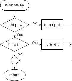
Figure 1: Main Loop
If you test drive the Lab06B.ino program you will see that it displays the number of bees along the way. This was a Lab 6 design challenge and is not a required part of Lab 6B. If you have not yet implemented this feature you can add it as part of the bonus lab.
What is New?
Here are some of the new concepts you will be exploring in this lab.
How to test and branch for the opposite sense of conditional expression
How to put a Microcontroller to Sleep
No new assembly directives or instructions are introduced in this lab.
Table of Contents
Update State_S2
Add the following comment blocks to the output decoder section of State S2. These are the two sections you will write in this lab. You are going to be responsible for adding the code at the correct location.
state_S2:
cpi r19, S2 brne end_switch
/* Output Decoder */ /* * step * 1 check to see if the bear is in the forest. * if the answer is yes, welcome the bear home. * 2 check to see if there are any bees in the room * if the answer is yes, count the number of bees */
Part I – In the Forest
Test (tst) the Row
In this part of the lab, you will write the code to see if the bear is in the forest (i.e., home) and learn more about conditional branching. Your code accomplishes this by checking the row the bear is currently in. The rows and columns of the maze are numbered from 0 to 19 (0x13) starting in the upper left hand corner. When the bear has found his way out of the maze he is in row minus one (r24 < 0). When this occurs, your code should call the subroutine InForest. You can also see how I wrote the equivalent test in C++ by opening the lab06B.ino program within the Arduino IDE.
As shown in Figure 1 and in the Lab06B.ino program C++ example, the code to check to see if the bear is in the forest is placed after TakeAStep and before EnterRoom. This code placement makes sense, given that if the bear is in the forest, there is no room to enter! If the bear is in the forest, call the to-be-written subroutine InForest.
Use the test instruction (tst) to find out if the value in a register is less than or greater than zero. Choose the corresponding branch instruction that will make this conditional check work as intended. For example, brne will not work because positive values will also cause it to trigger. If you would like additional help in writing the test to check to see if the bear is in the room see Appendix A, specifically the discussion on the test instruction.
InForest Subroutine
When the bear has left the maze and is now in the forest (i.e., home), call the following InForest subroutine. The InForest subroutine, when called, displays a 0 on the 7 segment display and clears the discrete LEDs. It then turns off the timer and disables the external interrupt. Once the forest is entered, the only way to restart the program is to press the reset button.
; ————————– ; ——- InForest ——— ; Input: none Outputs: none ; Warning: Subroutine enters power down mode. ; Press reset button to restart. InForest:
// Display 0 and turn off LEDs ldi r16, 0x3F mov spi7SEG, r16 // write segments for zero clr spiLEDS // all discrete LEDs off call WriteDisplay // Power-Down ldi r16, 0x05 // When bits SM2..0 are written to 010 (Table 9-1), out SMCR, r16 // and SE = 1 in the SMCR register (Section 9.11.1), sleep // with SLEEP the MCU enters Powerdown(Section 9.5) ret
How do I test my code?
The TakeAStep subroutine updates variables row and col as your bear travels through the maze. You may use TakeAStep to directly test if your new code is working – however, it may take a while to run each test. Instead, you will be using AVR Studio’s simulator/debugger to verify the operation of your new code snip-it.
Open the debug window . Run the program to allow the reset section to be completed.
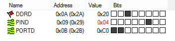
Stop program execution . In the I/O View window select PORTD. In the bottom window check PIND bit 2. This simulates pressing the button down.
Figure 2: Port D Registers Simulating Button Pressed
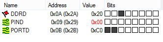
Single step the program once or twice. Then uncheck PIND bit 2. This simulates releasing the button. The external interrupt is configured to trigger on the falling edge of the input signal.
Figure 3: Port D Registers Simulating Button Released
Single step the program at least twice to initiate the call to the interrupt. You should now see the program counter go to the INT0 address (INT0addr) within the interrupt vector table (IVT).
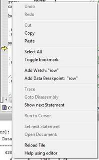
Although you could easily accomplish the following using the watch window as described in the last lab, I will now show you an alternative method. Open the Memory window (View and Memory). From the drop-down memory select Data. Find the address in SRAM Data Memory assigned to row by the assembler. In debug mode, you can find the address of the row variable by simply rolling over any instance of row in your program.
Figure 4: Rollover Pop-up Window Showing Variable Address in SRAM
If this does not work, you can also find row in your list (LST) or map files. For me row was located at memory location 0x101.
In the memory window’s Address text entry field, enter the Address of your row variable. You can now manually insert row values in the memory window by double clicking this location in memory and entering the value you want in the pop-up window.
Figure 5: Setting Data Values in Memory
Make sure that the Data memory is selected from the drop down menu (upper-left hand corner of the Memory window. In Figure 5, I have set the row so the bear is about to leave the maze.
Once you have entered your test value set a Breakpoint (F9) at the start of your new code segment and run your program . The program should then break at the start of the in forest check. While single stepping your program verify in the Processor window that the Zero flag Z is set to the correct value for the row number you entered. Test both true and false conditions.
Part II – Count and Display Bees
In the previous section, you checked to see if the bear is in the forest (i.e., home). In the following sections, you are going to check to see if the bear is in a room with bees. If the answer is yes, then you will add the number of bees in the room to the current total number of bees encountered up to that time. When the bear enters the forest you will display this number; specifically, the total number of times the bear has been stung.
Check Room for Bees
In lab 5A, you defined a new variable named bees to record the number of bees in a room. The subroutine EnterRoom returned the number of bees and the room number in register r24. You then wrote the code to separate these two values, saving them in variables room and bees. In my version, the number of bees is also held in register r22. Up to this point we have not done anything with the information on the number of bees in a room. In this section, as shown in Figure 1, you will be checking for and adding up the number of bees encountered in the maze in a block of code located after EnterRoom and before WhichWay. This block of code will be placed in-line (i.e, no subroutine) with the main loop. The C++ version of the lab (Lab06B.ino) also checks for and adds the number of bees with code placed inside (“in-line”) with the main loop.
The number of bees in a room was returned by EnterRoom. Using a compare instruction (cp) followed by a conditional branch instruction, check to see if this register is greater than zero. If the answer is yes, then do not count the number of bees, otherwise count the number of bees. This can get a little bit tricky, if you need additional help please see Appendix A.
Count Bees
You know the bear is in a room with bees, so all you need to do now is add the bees in the room to the total number of bees encountered in the maze up to this point. To hold this later value define a new variable named total_bees. As with all variables you define your variable using the BYTE assembly directive. Place the following assembly directive at the beginning of your program in the data segment (.DSEG).
total_bees: .BYTE 1 // total number of times bear was stung
Remember to always initialize variables at the same time you define them in the initialization (reset) section of your program.
; Initialize total number of bees clr r1 // assumed to always be zero by C compilers sts total_bees, r1 // no bees
Warning: If you do not initialize your variable, the number of bees encountered will not be reinitialized the second time you have your bear navigate the maze.
Now write a new subroutine named CountBees which counts the number of bees that have been encountered as the bear walks through the maze.
Display the Number of Bees
In this section, you will update the InForest subroutine (Part I) to display the number of bees encountered in place of simply displaying the number 0.
Modify your call to inForest to include the total number of bees as a parameter (see Lab06B.ino). If you could look “under the hood” as the Arduino C++ compiler translates the InForest(total_bees) subroutine call into machine code, you would see the total_bees (the first parameter) placed in register r24. We follow this convention in our assembly equivalent of this call. Specifically, load the total number of bees (total_bees) into register r24 before your call to inForest.
Next, delete the following two lines in my InForest subroutine (Part I).
InForest:
ldi r16, 0x3F mov spi7SEG, r16 // zero clr spiLEDS // all off call WriteDisplay
Replace these two lines with assembly code to call a to-be-written subroutine named Hex_to_7SEG and make sure to provide the proper input. The total number of bees (total_bees), the calling argument to InForest (sent in r24) is now sent to Hex_to_7SEG, which also takes as its calling argument the contents of register r24. The Hex_to_7SEG subroutine returns in r24 the segments to be turned on to represent this hexadecimal digit. Do not forget to move this return value into spi7SEG before calling WriteDisplay.
Hex_to_7SEG
This subroutine converts a hexadecimal value from zero (0x00) to fifteen (0x0F), into its visual representation on a 7 Segment display. To help you write this subroutine, I would recommend reviewing my lecture notes on the Indirect Addressing Mode. Remember to move the output from this subroutine to the correct register to display the number on the 7 segment display.
Warning: The Bytes Defined (.DB) in table are saved sequentially in the 16-bit wide Flash Program memory. Because a 16-bit wide word contains 2 bytes, the number of bytes defined on each line must be an even number.
A simple way to test if Hex_to_7SEG is working is discussed in “A Bug Story” (included in the next section).
Test Your Program
You may upload your program to quickly check to see if it works.The only change in the owner’s manual is the number of bees is now displayed when the bear enters the forest (leaves the maze). I would be surprised if your program works the first time in which case you will need to simulate the steps defined in the owner’s manual. See “Simulation and Debugging” in Lab 6 Part I for help here.
A Bug Story – Continued
Again I downloaded my program hoping it would work immediately and of course it did not. When my bear reached the forest segments a and b turned on but nothing else. It appeared that InForest was being called but the incorrect segments were being displayed. From this observation, I suspected that Hex_to_7SEG was not working. To test my theory I saved the binary number to be decoded into spiLEDS before calling Hex_to_7SEG. Now I could see what value was being sent to Hex_to_SEG to be decoded. Assembling, uploading and running my program I discovered that the binary number 00001000 (810) was being sent to subroutine as expected (the bear had encountered 8 bees). This seemed to show that I was correct and the decoder was not working. To further isolate the bug, I needed to use the debugger/simulator. To simplify the debugging process, I copied the subroutine call to the now empty main loop and set a breakpoint at the call. Now I could immediately test Hex_to_7SEG without having to run the rest of the program. In simulation at the break point, I set r24 equal to 8 to simulate the calling argument to Hex_to_7SEG. Stepping through the subroutine I discovered everything worked fine and that Hex-to_7SEG was returning 0x7F (segments to display 8) as expected. Very strange. It then hit me that I had not sent r24 to spi7SEG so although the answer was being returned to the calling program the return value had never made it to the display. After adding the missing move instruction everything worked as intended.
Share your Story
If you have a similar story of debugging your code, send it to me so I can add it to A Bug Story and help future students.
Lab 6 Deliverable(s)
Make sure to turn in the formatted list file with everything necessary for Lab 6. The new subroutines that should be in the report are WhichWay, InForest, CountBees, and Hex_to_7SEG. Remove all sections that are from include files. Do not turn in any other material. Please read the “Typical Lab Deliverable(s)” section of the Lab Grading Policy document contained in the Lab folder for detailed instructions for how to format your lab report.
All labs should represent your own work – DO NOT COPY.
Lab Notebook Your lab notebook should show your work done as part of this lab. To demonstrate your level of effort, record the time intervals over which you worked on each lab section. Specifically, note the current date and time at the top of each page. Lab notebooks are used to show the thought processes that went into the solution of a problem. More credit will be given to solution attempts than the actual solution.
Appendix A: The Test (tst) and Compare (cp and cpi) Instructions.
The following section is provided for those students who want additional assistance writing the in forest and bee test sections of the program.
For the inforest test we only need to determine if register (r24) is positive or equal to zero (r24 >= 0). Where the value in r24 equals the row coordinate of the bear. If the row is greater than or equal to zero then no action needs to be taken, otherwise we need to call the in forest subroutine. To find the answer to this type of question we use the test (tst) instruction.
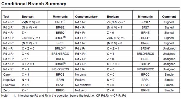
The test instruction performs the logical and operation on the operand with itself (Rd ← Rd & Rd). This operation is done in order to set and or clear SREG ALU flag bits Z and N. Looking at the “Conditional Branch Summary” Table below, we see that knowing the value of these two SREG bits allows us to quickly test to see if the value held in this register is negative (N = 1), positive (N = 0), and equal (Z = 1) or not equal to zero (Z = 0).
For the inForest test we need to test if the number is positive (N = 0), in which case the bear is still in the maze.
For the bees test we want to count the bees if the room has bees (r22 > 0). Where r22 holds the number of bees in the room. When we translate high level if expressions into assembly we invariably use the opposite sense of the test, in this case (r22 <= 0). This is done to allow the block of code to be execute if the original test is true to immediately follow the test. In other words if the r22 > 0 then run the code following, otherwise (r22 <= 0) jump over this code. Looking at the table we anticipate that this test will involve flag bits C and Z. The test instruction does not help with the carry bit so we must look to the compare (cp and cpi) instruction.
A compare instruction performs a subtract operation without a destination. You may be asking yourself, what is the point of subtracting two numbers if you don’t save the answer? Most of the time when you compare two items, for example in a C++ if instruction, you do not want the items being compared to be modified. You only want to know the relationship between the two numbers. For example, are the two numbers equal, is one greater than or equal to the other, or is one less than the other? In assembly, while the compare instruction does not save the result it does set all the SREG status flags associated with the subtract operation. When combined with the AVR’s extensive suite of conditional branch instructions (see “Conditional Branch Summary” table) designed to work with the compare instruction, you have a quick way of comparing two values and taking action.
Assuming the use of a compare immediate instruction (cpi Rd, Rs), where Rs is a constant, in this case 0, for our bees test problem, we want to find the assembly instruction corresponding to Rd <= Rs. From the table we see that the instruction is Branch if Same or Higher (brsh), with a note attached. The note tells us to “Interchange Rd and Rr in the operation before the test. We therefore would want to make Rd = 0 and Rs = r22. Unfortunately, for a compare immediate instruction Rs is a constant and so we must switch to a compare instruction (cp) and use some arbitrary register set to 0 for Rd. Here is how the final test would look.
// if(bees > 0); // C++ test, with equivalent Assembly Code clr r16 // see Conditional Branch Instruction Summary Table cp r16, r22 // Note: 1 Interchange Rd and Rr in the operation
// before the test
brsh no_bees
block of code to be executed if the room has bees.
no_bees:
Appendix B: How do I divide a number by 2?
In assembly language we always divide in multiples of 2 by shifting right 1 place for each factor of 2. The logical shift right instruction shifts an unsigned (counting) number by one place to the right – just what we need. For example, 4 = 01002 shifted right one place gives you 2 = 00102. Never use the div instruction to divide by two.
In most microprocessors a single shift right logical instruction is included as part of the instruction set. For the AVR processor this is the LSR (Logical Shift Right) instruction.
The AVR also includes an Arithmetic Shift Right (ASR) instruction. While the logical version (LSR) of the shift instruction always inserts a zero into the most significant bit, the arithmetic version (ASR) recycles the sign bit. In this way the sign of the number (plus or minus) is preserved.
In summary, for unsigned numbers to divide by 2 use the logical shift right instruction. For signed numbers always use the arithmetic shift right instruction. Either shift instruction will work in our application. Do you know why?
[/av_textblock]
[av_textblock size=” font_color=” color=” av-medium-font-size=” av-small-font-size=” av-mini-font-size=” admin_preview_bg=”] Lab 6 is worth 30 points. Shortest Path is worth 10 points, Your Path is worth 10 points, In Forest (Lab 6B) is 5 points, and Count Bees (Lab6B) is 5 points.
The WhichWay subroutine that was written for Lab 3 tells the bear which way to go by setting switch positions SW1 and SW0 for the direction and SW3 and SW2 for which way to turn. We will now be updating it to navigate through the maze using the logic developed in Prelab 1.
In this lab, you will first create an assembly version of the shortest path solution called ShortWhichWay with. Next, you will implement the flowchart you wrote in PreLab 1 and translated into assembly code as part of PreLab 6.
When you are done teaching the bear how to get out of the maze by himself, you will no longer need any of the eight switches as inputs. No more switches!
What is New?
Here are some of the new concepts you will be exploring in this lab.
Translating a flow chart and high-level code into assembly.
No new assembly directives or instructions are introduced in this lab.
Table of Contents
Create the Lab 6 Project
If you are using a lab computer, I would recommend saving all of your files to a flash drive. Do not forget to save often. At the end of the lab, do not forget to save the latest version and take your flash drive with you.
Open AVR Studio and create a new Project named Lab06 (see Lab 1 for detailed instructions)
Copy over maze.inc, pseudo_instr.inc, spi_shield.inc, testbench.inc, and upload.bat from Lab 5.
Open the upload.bat text file in notepad (right-click edit) and change the filename from Lab05.hex to Lab06.hex
Copy the text in Lab05.asm into Lab06.asm
Update the information in the title block.
Build your project and verify you are starting with zero errors and zero warnings.
Before You Start
Verify that SRAM variable dir is initialized so the bear is facing North (dir = 0x03). Verify that SRAM variable room is initialized so the bear is in an empty room (room = 0x00). Verify that SRAM variable next_state is initialized to S0 (next_state = 0x00). Verify that SRAM variable row is initialized to the starting location just outside of the maze. (row = 0x14). Verify that SRAM variable col is initialized to the starting location (col = 0x00). Verify that SRAM variable walk is initialized so the bear does not automatically take a step. (walk = 0x00).
A Little House Cleaning
Open the pseudo_instr.inc include file in AVR Studio. You need to Build your project (step 6 in “Create the Lab 6 Project” for the include files to be shown in the Project window.
Move the subroutines TakeAStep, EnterRoom, and IsHallway created in Lab 5 from the Lab6.asm main application to the pseudo_instr include file. Optionally, you may delete TestIsHallway or also move it to the pseudo_instr include file. You may notice that in the figure it shows Lab6A not Lab6.asm. I created a new project for each part of a lab. This allows me to easily move from one to the other. You have the option of simply making a copy of your labs so that you can step back in time.
At this time, the main application Lab6.asm should only have the initialization (reset), main loop (loop), the interrupt service routine (INT0_ISR) and the subroutines Delay and Pulse. All other subroutines should be located in include files or deleted. Any subroutines created for design challenges should also be moved to the include files.
Part I – Shortest Path
Before you implement your solution, let’s verify that your nearly complete program is working by implementing the shortest path (fewest bees) solution to the maze.
Step-by-Step Solution
Remove the code that updates the variable dir based on switch positions from the main program. In the main program, you read the switches and set variable dir. You no longer use the switches on the shield to set dir, or anything else for that matter, so delete this section of your program.
Add a call to a to-be-written ShortWhichWay subroutine. Place the subroutine call after the bear takes a step and enters a room (State S2). As shown here, the direction variable dir is updated after each call to ShortWhichWay.
Copy and Paste my ShortWhichWay subroutine which implements the shortest path solution. I have superimposed the Arduino version of the WhichWay subroutine from Lab06A.ino so you can compare the two implementations.
; — Which Way Do I Go? — ; Called from main program ; Input: r24 = direction, r22 = room ; Output: r24 = direction ; No registers or flags are modified by this subroutine ShortWhichWay:
mov r17, r24 // save to temporary register // if(!rightPaw(dir, room)) rcall RightPaw // r22 = room, r24 = dir tst r24 brne else_if_hitwall // dir = turnRight(dir); mov r24, r17 // move direction to calling argument rcall TurnRight // new direction now in r24 rjmp which_end // else if (hitWall(dir, room))
else_if_hitwall:
mov r24, r17 rcall HitWall // r22 = room, r24 = dir tst r24 breq else // dir = turnLeft(dir); mov r24, r17 rcall TurnLeft // new direction now in r24 rjmp which_end
else:
mov r24, r17 // do not change direction
which_end:
ret
Assemble and upload your new program. If everything is working, your bear should now be able to navigate his way out of the maze, encountering the fewest number of bees. You should only need to push the step button when a decision needs to be made (corner, intersection, or encounters bees). And the really good news is you no longer need to toggle any switches!
Test Your Program
You may upload your program to quickly check to see if it works. An updated owner’s manual is provided in the next section to help you step through the maze. I would be surprised if your program works the first time in which case you will need to simulate the steps defined in the owner’s manual. See “Simulation and Debugging” for help here.
Updated Owner’s Manual
Follow these steps to navigate a maze.
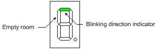
Download and run the program. The bear should be shown at the entrance of the maze – an empty room. The north facing direction 7-segment LED should be blinking instructing the bear to walk north. Toggling the switches should have no effect.
Push the button to provide the bear with the directions. You should now see the room you entered displayed along with the direction in which the bear should now proceed.
Repeat step 2 until the bear makes it to the forest.
Push the button telling the bear to take a step. The bear should now be shown in the first room – a room with a west facing wall. You should also see the direction in which the bear should now proceed as defined by your WhichWay subroutine.
Push the button to provide the bear with the direction. You should now see the bear walk (hallway blinks on and then off) until a decision needs to be made (a corner, fork in the road, or bees). The room the bear is in along with the new direction (blinking) in which the bear is facing, as defined by your WhichWay subroutine, should now be displayed.
Repeat steps 5 until the bear makes it to the forest. What should be displayed on the seven segment display when the bear enters the forest is for now, undefined, so anything displayed is okay.
Simulation and Debugging
If your program does not work, then of course you will need to use AVR Studio’s simulator/debugger.
To faithfully simulate your program you will need to manually set the timer flag and trigger an external (button) interrupt as your bear travels the maze. If your bear gets confused fairly deep into the maze then set the row and column a few steps before the problem area and then set the timer flag and trigger an external (button) interrupt for the few steps needed for him to encounter the problem.
Don’t forget these helpful tips. You can right-click any variable and add it to the watch window. If the watch window does not already show values in hexadecimal, right click inside the window and select “Display all Values as Hex.”
Part II – My aMazing Solution
Replace the shortest path solution to the maze with the path defined by your flowchart from PreLab 1 as implemented by your WhichWay assembly subroutine written in PreLab 6. Rename that subroutine to be MyWhichWay in order to avoid any confusion over which version of WhichWay you are calling (from lab 3, the shortest path, from prelab 6).
This portion of the lab is not optional!
A Bug Story
Like you, I downloaded my program hoping it would work immediately and of course it did not. The direction segment stayed pointing North and a closed room appeared on the second step. My first course of action was to simplify, so I commented out most (I thought I had commented out all) of the new code and replaced it with the original WhichWay code. I then uploaded my simplified program and the problem did not go away. I suspected I had somehow broken the original version; but how? After simulating my call to WhichWay I rediscovered that the part of the code that called WhichWay saved the new direction returned in r24 to variable dir. I thought the new WhichWay did this step. Going back to WhichWay I discovered that I had not commented out a new section where I added push and pop r24 instructions to make my subroutine more transparent. Instead it broke the program. I removed the push/pop and my bear was on his way again.
[/av_textblock]
The stack pointer of the AVR processor is always pointing to the next available location in SRAM to store temporary data. In Lab 2, I moved the stack pointer to the top of memory with the following code snip-it.
ldi r16,low(RAMEND) // RAMEND address 0x08ff out SPL,r16 // stack Pointer Low SPL at i/o address 0x3d ldi r16,high(RAMEND) out SPH,r16 // stack Pointer High SPH at i/o address 0x3e
As your code becomes more complex, the possibility of losing control of the stack becomes a very real possibility, resulting in a stack underflow or overflow condition.
Question 2 In Lab 3A Appendix A Rules for Working with Subroutines, I gave you a few rules to remember when writing your main program and subroutines, which of these rules, if not followed, would result in a stack underflow and/or overflow condition. Explain your answers.
Part 2 – Translating your flowchart from PreLab 1 into an assembly program
Question 3 One of the lab objectives is to see if the bear is in the forest (i.e., home). Your code will accomplish this by checking the row the bear is currently in. The rows and columns of the maze are numbered from 0 to 19 (0x13) starting in the upper left hand corner. When the bear has found his way out of the maze he is in row minus one (row < 0). How would you represent minus 1 in hexadecimal using 2’s complement notation?
Question 4Translate your flowchart from PreLab 1 into an assembly program. If you were asked to plot a new path through the maze, and have not done so, please see me (lab instructor) as soon as possible. Note that if your path does not go through the target square corresponding to the last four digits of your student ID, you will receive a zero for lab 6. If you are not sure, you are responsible for asking.
In PreLab 1 you designed a flowchart for the WhichWay routine. This flowchart from PreLab 1 used subroutine names for sensor (used in a conditional expression) instructions Hitwall, RightPaw, and LeftPaw and actuator (take some action) instructions TurnLeft, TurnRight, TurnAround, InForest and CountBees. By the end of lab 3 most of these were no longer names, but working assembly subroutines. Working from your PreLab 1 flowchart, and incorporating calls to these subroutines, write an assembly program to implement the flowchart.
For help read Lab 6A which shows you how to translate the shortest path flowchart into an assembly program.
What Should I Turn In?
Turn in the following material three pages. Make sure all your original work is in your Lab Notebook. All written material must be typed or very neatlydone in ink. Once again please do not copy.
Page
Title page with the pre-lab number, your name, today’s date, and the day your lab meets.
Answers to the four questions. Do not forget to summarize the question and highlight your answers.
Your approved flowchart from Prelab 1.
Your WhichWay subroutine. This may be done in AVR Studio (recommended).
[av_textblock size=” font_color=” color=” av-medium-font-size=” av-small-font-size=” av-mini-font-size=” admin_preview_bg=”]
Is your finger tired from pushing the button every time you want the bear to take a step? In this last part of lab 5, you are going to teach your bear how to walk down a hallway by himself to speed up his navigation through the maze.
What is New?
Here are some of the new concepts you will be exploring in this lab.
Implementing Logical Operators (&&, ||) in Assembly
4-State Finite State Machine (FSM)
No new assembly directives or instructions are introduced in this lab.
Table of Contents
Part I – IsHallway
What Question Does IsHallway Answer?
In the second part of this lab you are going to teach the bear how to walk down a hallway until he encounters bees, a corner, or an intersection. Clearly, before you can tell the bear to walk down a hallway, you need to test for these conditions – is the bear in a hallway without any bees? To help answer that question, you are going to write a new function named IsHallway.
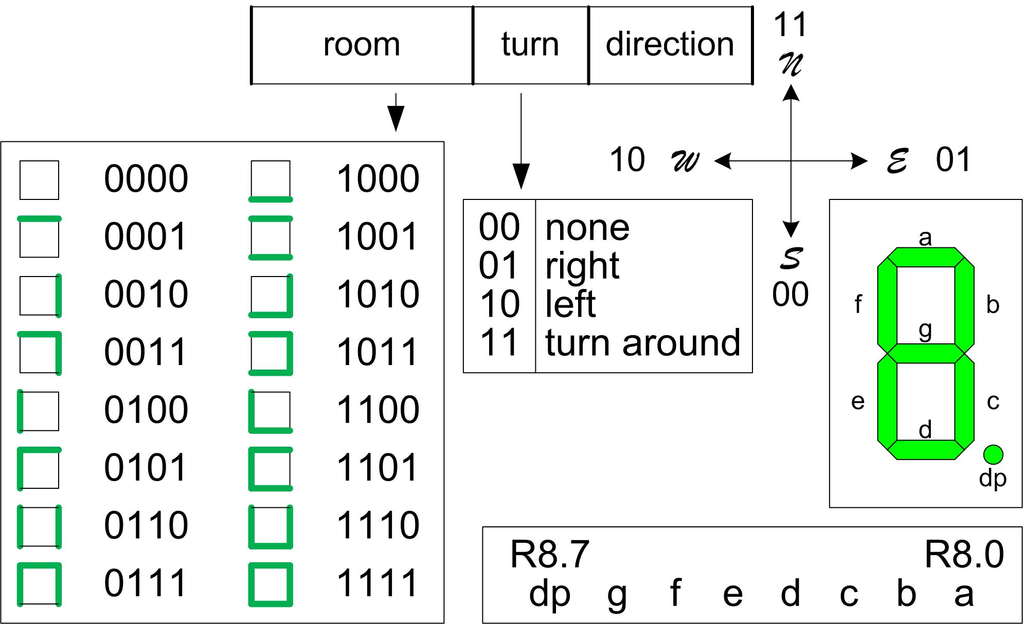
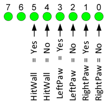
The hallway question is answered by looking at Figure 1 Programmer’s Reference Card. Here we see that Room 6 (room = 01102) is a vertical hallway and Room 9 (room = 10012) is a horizontal hallway. If room equals either of these two values (it is a hallway) and the hallway does not contain any bees, then your function will return a non-zero value (true), otherwise the function will return zero (false).
Figure 1: Programmer’s Reference Card
The bee question will be answered by testing if r22 (bees) is equal to zero (tst).
Arduino C++ IsHallway
In the previous section I described how IsHallway works in words. A more concise answer is provided by simply looking at the C++ code which does the equivalent operation. If you open the Arduino script Lab05B.ino you will see IsHallway defined as…
As you have learned in past labs, functions return values in the r24 register. Following this convention allows your functions to be called from C++ and assembly. For these functions you did not push/pop r24 allowing the register to provide the answer to the question asked (ex. did your right paw touch a wall?). If your function, like IsHallway, returns a Boolean value (true or false) then the calling program immediately executes a tst instruction followed by a breq (answer is false) or brne (answer is true) instruction. The branch selected is based on the program path you wish to take.
Use the comments in the following IsHallway template to complete your new function. Do not forget to add your own comments.
; ————————– ; — Is this a Hallway? — ; input r24 = current room (room), r22 = bees ; output r24 = 0 if answer is false (r24 == 0), ; otherwise the answer is true (r24 != 0). ; The answer is true if the bear is in a hallway ; without any bees. ; no registers are modified by this subroutine ; ————————- IsHallway: // return (bees == 0x00 && (room == 0x09 || room == 0x06));
1. Test (tst) if the room has bees R22 != 0x00. If the answer is yes (brne), go to answer_is_no. 2. Compare (cpi) room to a horizontal hallway (room == 0x09). If the answer is yes (breq), go to answer_is_yes 3. Compare (cpi) room to a vertical hallway (room == 0x06). If the answer is yes (breq), go to answer_is_yes
answer_is_no:
ldi r24, false // room is not a hallway or contains bees rjmp endOfHallway
answer_is_yes:
ldi r24, true
endOfHallway:
ret
Test IsHallWay
Here is a subroutine to test your new IsHallWay function named TestIsHallway. To display the answer, TestIsHallway uses discrete LEDs 5 and 4 as shown in Figure 2.
Figure 2: Test LEDs for TestIsHallway
; ————————– ; —– Test IsHallway —– ; Called from LED display section in the main loop ; Input: r24 Outputs: spiLEDs bits 5 and 4 only
TestIsHallWay:
push r16 mov r16, spiLEDS tst r24 // test return value from isHallway brne inHallway sbr r16, 0b00010000 // Bear is not in hallway, so turn on LED 4 cbr r16, 0b00100000 rjmp doneHallway
inHallway:
sbr r16, 0b00100000 //Bear is in hallway, so turn on LED 5 cbr r16, 0b00010000
doneHallway:
mov spiLEDS, r16 pop r16 ret
Place TestIsHallway in the Test Subroutines section of your program, which is after the main loop.
Add calls to your new IsHallWay and my TestIsHallway procedures in your discrete LED display area of the main loop.
Before proceeding to the next section, upload your program and test your IsHallWay function to make sure the bear knows when he is in a hallway (LED 5 is ON) or not (LED 4 is ON), or if he sees any bees (LED 4 is ON).
You will be adding IsHallWay in the next section as part of your Finite State Machine (FSM). Now that you have tested your IsHallway subroutine you may delete this section of code or keep it to provide additional insight into the operation of your FSM.
Part II – A little Animation
If the bear is in a hallway we want him to walk down the hallway. Specifically we want him to mimic the user pressing the button.
Software Implementation of a 4-State Finite State Machine
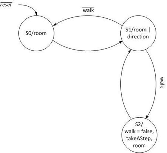
To teach our bear to walk down a hallway, we will be adding a fourth state to our FSM as described in Figure 3.
Figure 3: 4-State Moore Finite State Machine (FSM)
In Lab 4 Part A “Software Implementation of a 2-State Finite State Machine” you built your first FSM. In Lab 4 Part B “Software Implementation of a 3-State Finite State Machine” you extended your design to include a third state. Applying what you learned in Lab 4, add a 4th state as defined by Figure 3 “4-State Moore Finite State Machine (FSM).” As always if you need additional help you can look at the Arduino Script version of the lab (Lab05B.ino). That’s it! Have fun helping your bear solve the maze. That is of course after you have debugged the program.
The hallway variable that is present in Figure 3 is referring to the output from the IsHallway subroutine. Use the diagram to figure out where in the code you will need to call IsHallway and how that will be utilized in the next_state decoders. Remember, you cannot go directly to another state and must update the next_state variable with the correct value.
Test Your Program
You may upload your program to quickly check to see if it works. An updated owner’s manual is provided in the next section to help you step through the maze. I would be surprised if your program works the first time in which case you will need to simulate the steps defined in the owner’s manual. See “Simulation and Debugging” for help here.
On a personal note, when I wrote this program for the first time, I do not know how many hours it would have taken to get it working without the simulator.
Updated Owner’s Manual
Follow these steps to navigate a maze. You can follow along by opening Lab05B.ino within the Arduino IDE.
After you upload and run the program, no room should be displayed (the bear is outside the maze). Place both direction switches up, all other switches should be in the down (off) position.
The North direction 7-segment LED should be blinking telling the bear to walk North.
Push the button telling the bear to take a step. The bear should now be shown in the first room – a room with a west facing wall.
Point the bear in the direction you want him to proceed by setting the direction switches.
Push the button to provide the bear with the directions. You should now see the bear walk (hallway blinks on and then off) until a decision needs to be made (a corner, fork in the road, or bees). The room the bear is in along with the direction (blinking) in which the bear was told to walk should now be displayed.
Repeat steps 4 and 5 until the bear makes it to the forest.
Simulation and Debugging
You have added a lot of code to your program and the probability that it will work the first time you upload it are not good. Consequently, you will need to use the simulator to find the problem.
Here you will use the techniques learned in previous labs to set timer and external interrupts. In addition I would recommend using the watch window to quickly update and track your variables.
If it is not already open from the menu bar select View and Watch. Now left click the variables you want to update and track and select and from the pop-up menu select
Add Watch: “some variable”
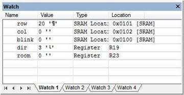
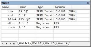
When I was debugging my program I watched variables row, col, blink, state, and room. Here is what their values are after initialization.
Erratum: The original form of the state variable, was a variable named blink. It is this variable that is shown in the screen capture here and in subsequent screen captures.
As you can see the bear is standing just outside the maze (row = 20 col = 0) facing north (dir = 3) in an empty room (room = 0). All numbers are in decimal so you may want to convert to hexadecimal.
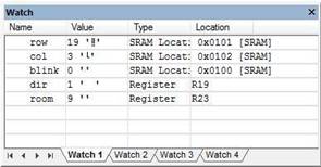
Instead of spending time walking your bear to a location that includes a bug, you can now simply modify the variable in the watch window to take your bear directly to the problem. In this sample watch window I have positioned my bear in the first hallway.
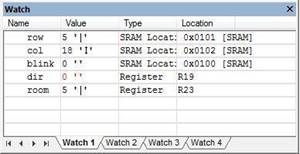
Here are two watch windows testing the first instance of the bear entering a room with bees. The two cases are testing the effect of variable blink on this room.
In this final example, my bear is entering the third left hand turn of the shortest path.
Design Challenge B – Walk into a Wall (2 points)
This is the second of two design challenges. You can skip these sections if you are happy receiving a passing grade (“C”) on the lab. If you want to receive a good or excellent grade you will need to accept one or more of the challenges.
Modify TakeAStep to not take a step and to set the four remaining LEDs (3 to 0) if the bear walked into a wall.
Lab 5 Deliverable(s)
STOP Read the Lab READ ME document contained in the Labs Folder. Be absolutely sure you have followed all instruction in the “Lab Formatting” section of this document. Points will be deducted if you do not follow these instructions. You have been warned (again, and again and again…)
Make sure your lab notebook is up to date. Follow the guidelines provided in the “Lab Notebook” section of the Lab READ ME document.
Make sure you have read and understand the “Plagiarism” section of the Lab READ ME document, especially if you are repeating the class.
All labs should represent your own work – DO NOT COPY.
[/av_textblock]
[av_textblock size=” font_color=” color=” av-medium-font-size=” av-small-font-size=” av-mini-font-size=” admin_preview_bg=”] Lab 5A: Take a Step and Enter a Room/ Indirect Addressing Mode
[/av_textblock]
[av_textblock size=” font_color=” color=” av-medium-font-size=” av-small-font-size=” av-mini-font-size=” admin_preview_bg=”]
At present, you enter the room by hand (SW7 to SW4). In this lab you will write subroutines to teach your bear how to take a step and enter a room. To accomplish your task this lab includes a digital description of the maze. No more room switches!
FUTURE ALERT!
In the PreLab for Lab 06 you will be translating your flowchart from PreLab 1 into an assembly program. If you were asked to plot a new path through the maze, be sure and receive the instructor’s approval before doing the PreLab. If you are not sure, you are responsible for asking.
If you decide to work on the “Congratulatory Tune” section of the Bonus Lab for Lab 6, you will need to purchase an inexpensive speaker and a carbon film resistor, 270 ohms at 250 mW. You will be wiring the circuit as drawn in the Arduino Proto-Shield schematic.
What is New?
Here are some of the new concepts you will be exploring in this lab.
Working with the Indirect Addressing Mode
The indirect addressing mode instruction lpm is introduced in this lab.
Table of Contents
Create the Lab05 Project
If you are using a lab computer I would recommend erasing everything in Drive D and using this area for our project. Do not forget to save often. At the end of the lab do not forget to save to your Flash drive.
Open AVR Studio and create a new Project named Lab05 (see Lab 1 for detailed instructions)
Copy over maze.inc, pseudo_instr.inc, spi_shield.inc, testbench.inc, and upload.bat from Lab 5.
Open the upload.bat file in notepad (right-click edit) and change the file name from Lab04.hex to Lab05.hex
Copy the text in Lab04.asm into Lab05.asm
Update the information in the title block.
Build your project and verify you are starting with zero errors and zero warnings.
Cleanup
Before we begin, lets do a little more house cleaning. The items preceded by an empty box ☐ are probably not done and you will need to take some action. The items preceded by a checked box most likely have been completed, but you should double check to avoid debugging your program.
☐ The SRAM variable dir should be initialized so the bear is facing North (dir = 0x03).
☐ Verify that SRAM variable room is initialized so the bear is in an empty room (room = 0x00).
☐ Verify that SRAM variable next_state is initialized to state S0 (next_state = 0x00)
Take a Step and Enter the Room
As mentioned in the introduction, you currently enter a room within the maze by hand (SW7 to SW4). In this lab you will rewrite subroutine TakeAStep and write a new subroutine named EnterRoom to navigate a digital version of the maze (maze.inc). No more room switches! To see how this will work open the Lab05A Arduino Sketch within the Arduino IDE, and follow the steps defined in the “Updated Owner’s Manual” located near the end of this lab.
Add the following code to the output decoder section of state S2. loop: : case_S2:
cpi r20, S2 // test is optional brne end_switch // output decoder : lds r20, dir // input arguments are dir, col and row lds r22, col lds r24, row rcall TakeAStep sts col, r22 // update column and row sts row, r24 rcall EnterRoom // inputs to EnterRoom are outputs from TakeAStep mov r22, r24 // save a copy of # of bees in the room cbr r24, 0xF0 // remove the # of bees from the room sts room, r24 // save the room number swap r22 // swap # of bees to the least significant nibble cbr r22, 0xF0 // remove the room from the # of bees sts bees, r22 // save number of # of bees in the room
Notice that the new code incorporates your original call to TakeAStep included in the output decoder section of state S2. This original version simply read switch values SW7 – SW4 and placed them in variable room. In this lab the subroutines TakeAStep and EnterRoom perform the same function, without the switches. Here is what is happening in the code you just added; TakeAStep takes as input arguments row, col, and dir and computes the coordinates of the room the bear is entering. Consequently, it outputs the row and col address of this new room. EnterRoom takes these coordinates (row, col) as input arguments (r24, r22), computes an address within the encoded maze (maze.inc) and returns the room and bees at this address (r24 = bees:room).
The program then isolates the room from the bees and saves both into their respective variables (room and bees).
Once again notice that to maintain C++ compliance, arguments are sent in registers r24, r22, and r20. Function return values (bees:room) are contained in registers r24.
If you were to assemble your program now, you would receive a large number of errors, as the assembler looks for variables and a subroutine that is not there. We will be defining those variables at the beginning of the next section and writing the missing subroutine (EnterRoom) shortly.
Take a Step
Before we rewrite TakeAStep define three new SRAM variables to hold our current location (row and col) in the maze and the number of bees in a room.
.DSEG room: .BYTE 1 dir: .BYTE 1 next_state: .BYTE 1 // FSM next state walk: .BYTE 1 row: .BYTE 1 // the bear is in the room at this row col: .BYTE 1 // and column address bees: .BYTE 1
It is good programming style to always initialize variables as soon as you define them. At the beginning of the maze we want the bear located in row = 0x14 and col = 0x00. In the reset section of your program initialize SRAM variables row and col to these values. Next, initialize variable bees = 0 indicating that the bear has not yet encountered any bees. Do not forget to comment your code.
Now, write a subroutine to modify these variables containing the bear’s current room location (row and col) based on the direction you want the bear to walk. Specifically, translate the following truth table into assembly code. You may use any technique you like.
Table 1: Modification of row and column based on direction bear is facing.
dir
row
col
Comment
00
+
take a step South by incrementing the row
01
+
take a step East by incrementing the column
10
–
take a step West by incrementing the column
11
–
take a step North by decrementing the row
Do not forget to add your own comments to your code.
; —— Take A Step —— ; Called from INT0_ISR and main loop for animated version ; input r24, r22, r20 = row, col, dir ; output r24, r22 = row, col ; No other registers are modified by this subroutine. ; note: This simplified version can walk through walls ; ————————- TakeAStep:
; push registers modified by your subroutine ; based on direction (r20) incr/decr row/col as defined in Table 5.1 ; pop registers modified by your subroutine ret
The simplest solution conceptually would be to implement a high level language if-then-else construct in assembly using cpi and brne, or bst and brts instructions. For additional assistance review your Lab03A code (TurnLeft, TurnRight, WhichWay).
Creative Corner – TakeAStep using Indirect Addressing Mode
The indirect addressing mode is the most elegant, the most difficult to understand, and of course, the method I used to program the TakeAStep subroutine. The lookup table solution shown in the Arduino Sketch Lab05A, would be implemented in assembly using the lpm instruction. My AVR Studio version of Lab05A uses the ijmp instruction. Please remember to indicate on the cover sheet of your lab report if you implemented this Creative Corner version of the subroutine.
Define the Maze
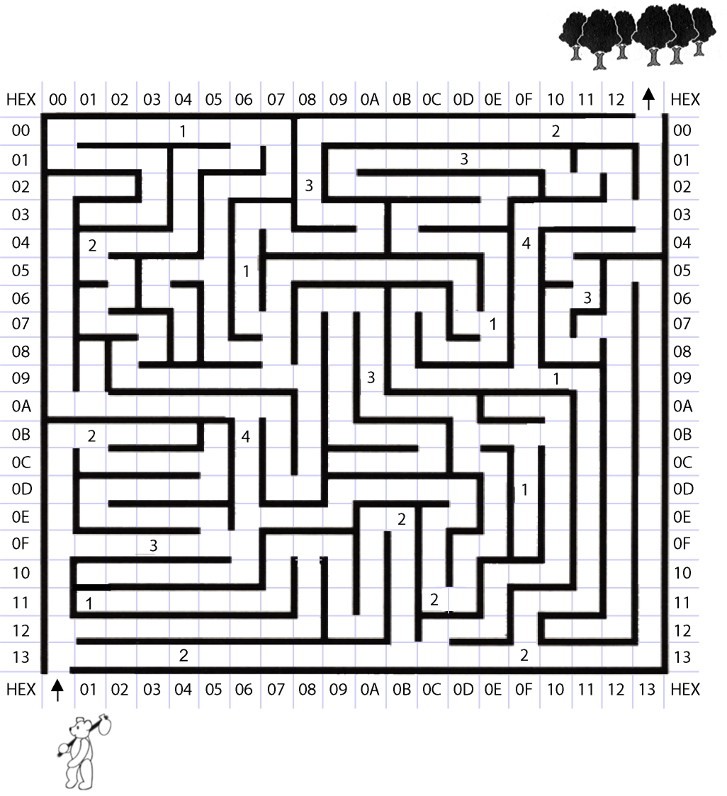
Before we can enter a room we must define all the rooms in the maze. Here you will use the maze you created in Prelab 5 (if you did not complete the prelab, you can find the maze without the bees here). Move your maze.inc file into the Lab05 project folder.
Figure 1: The Maze
Open the maze.inc file you created in the pre-lab (File > Open File…).
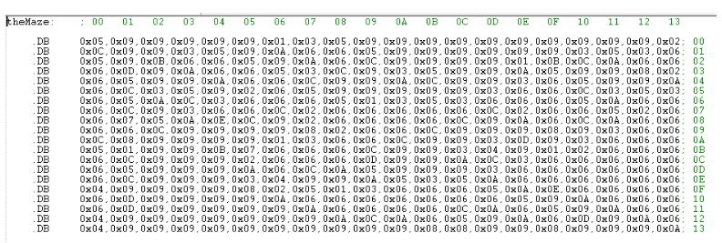
Figure 2: An Encoded Maze (maze.inc file without Bees)
Unlike Figure 2, your version should include the bees in the maze. Before we continue, let’s review how the maze is constructed (prelab 05). As you can see in Figure 2, I have organized the rows and columns of the table to match our maze (Figure 1). Each entry in the table defines the room and bees at that row and column address. The definition of the room corresponds to the switch positions you have been manually entering up to this point in the course. For example; after taking his first step, the bear is in the room at column address 0016 and row address 1316. Looking at our maze (Figure 1), we see at these coordinates is a room with only a west facing wall. The Programmer’s Reference Card (see Figure 3), tells us that a room with only a west facing wall is encoded as 01002 = 0x04. Looking at the first entry in the last line of the table, we see our room encoded as 0x04.
Figure 3: Programmer’s Reference Card
Include your definition of the maze by adding the following include assembly directive to your program.
Now that our bear has taken a step and we have our maze encoded, it is time to write the EnterRoom subroutine. The TakeAStep subroutine has already updated variables row and col to correspond to the coordinates of room we are currently in, so now all we have to do is translate that information into the a byte index into table theMaze. With a sharp pencil (or your smart device) and a little math you will discover that the byte index of a room as a function of the row and column is given by the equation 20 x row + col.
Do not forget to add your own comments. Please, do not copy and paste my explanatory text.
; ————————– ; —— Enter a Room —— ; Called from main program ; input r22, r24 = col, row ; output r24 = bees:room ; no other registers are modified by this subroutine. EnterRoom:
; Push registers modified by your subroutine, including ZH and ZL. ; Do not push registers used to return values r24 and r22. Write the code to save registers here // Step 1: Base Address ldi ZL,low(theMaze<<1) // load base address of theMaze into Z. ldi ZH,high(theMaze<<1) // Step 2: Calculate Byte Index Using instructions mul, add, and adc, compute the index of the room by writing the code to implement equation 2010*row+col here. Be careful this is a 16-bit number so you need to add the carry (adc) into the most significant byte. To add only the carry, set a scratch register to zero (clr r2) and add it along with the carry (adc r1, r2). // Step 3: Add Index to the Base Address and Load Room with Bees Add the 16-bit index to the base address of theMaze by writing the code to implement equation ZH:ZL = ZH:ZL + r1:r0 here. Again, you will need to use both the add and adc instruction to add these two 16-bit numbers together. ; load the room and bees from program memory using the indirect addressing mode. lpm r24,Z // load the room with # of bees indirect
; pop registers modified by your subroutine, including ZL and ZH Write the code to pop the registers here. ret
Test Your Program
You may upload your program to quickly check to see if it works. An updated owner’s manual is provided in the next section to help you step through the maze. I would be surprised if your program works the first time in which case you will need to simulate the steps defined in the owner’s manual. See “Simulation and Debugging” for help here.
Updated Owner’s Manual
Open the Lab05A Arduino Sketch within the Arduino IDE, and follow these steps to see how your program should navigate the maze.
After you upload and run the program, no room should be displayed (the bear is outside the maze). Place both direction switches up, all other switches should be in the down (off) position.
The North direction 7-segment LED should be blinking telling the bear to walk North.
Push the button telling the bear to take a step. The bear should now be shown in the first room – a room with a west facing wall.
Point the bear in the direction you want him to proceed by setting the direction switches.
Push the button to provide the bear with the direction you wish him to walk. The bear now takes a step (TakeAStep) and enters the next room (EnterRoom) as defined by your encoded maze (maze.inc) file. You should now see the room displayed along with the direction in which the bear was told to walk (note: the direction may not be visible if it is obscured by a wall).
Repeat steps 4 and 5 to verify the basic operation of the program. You do not need to guide the bear all the way to the forest.
Simulation and Debugging
Set a break point at your call to ReadSwitches and at the beginning of the INTO_ISR. Run to the first break point and set direction switches so the bear is facing north, we no longer use the room switches.
Step over the ReadSwitches subroutine. Register R06 should be equal to three (0x03). Initiate an external interrupt by toggling PIND bit 2 as described in Lab and duplicated here.
Check PIND bit 2
Take at least two steps 2x . The check mark may disappear after the first step, this is due to the simulation of an internal synchronization circuit. It should reappear after the second step.
Uncheck PIND bit 2.
Single step the program . You should within a few steps find yourself in the interrupt vector table (IVT). Take the jump into the INT0_ISR. Set a breakpoint or step to your call to TakeAStep. SRAM variable row and register R24 should equal 0x14 (decimal 20) and variable col and register R22 should equal 0x00. The direction and register r20 should be three (0x03).
Step over TakeAStep. You have just told the bear to take a step in the North direction, so register R24 = 0x13 and R22 = 0x00. If they are not, then you should repeat steps 1 to 3 and this time step into TakeAStep and locate the bug.
Step to and over EnterRoom. The bear should now have entered the first room, one with a west facing wall, which means register R24 = 0x04. If the bear is not in this room, then you should repeat steps 1 to 4 and this time step into EnterRoom and locate the bug. Review the “Define the Maze” Section of this lab if you are not sure why R24 should equal 0x04.
Congratulations, your bear has now taken his first step and entered the maze. You now can upload your program and manually walk the bear around the maze. If you run into a bug along the way you should return to the simulator and manually enter the row and column just before the bug was discovered on the board and then repeat steps 1 to 5 having the bear enter the problematic room.
Design Challenge A – Room with Bees (1 – 3 points)
This is the first of two design challenges. You can skip these sections if you are happy receiving a passing grade (“C”) on the lab. If you want to receive an good or excellent grade you will need to accept one or more of the challenges.
In the Pre-Lab you encoded the number of bees in the room. Modify your program so as the bear walks into a room with bees, the number of bees in the room is displayed on the seven segment display for at least half a second (500 ms). After this delay the room is again displayed. This modification should not affect the performance of the rest of the lab.
Lab Demonstration
You may be asked to…
Simulate an external interrupt
Demonstrate using AVR Studio that the SRAM variable room is updated every time the button is pressed.
Demonstrate the correct operation of your program as defined in your “Owner’s Manual” found at the beginning of this lab.
Make a backup copy of your project folder before moving to Lab 05B
[/av_textblock]
[av_textblock size=” font_color=” color=” av-medium-font-size=” av-small-font-size=” av-mini-font-size=” admin_preview_bg=”]
Up to this point you have worked with an illustration of the maze. To describe a room you have had to manually enter the room number.
Figure 1: Maze to the Forest
In this lab you will begin working with an encoded version of the maze located in a look-up table.
Figure 2: An Encoded Maze
The green numbers across the top and right side of the encoded maze correspond to the columns and rows of the maze. Each entry in the table defines the room at that row and column address. The definition of the room, corresponds to the switch positions you have been manually entering up to this point in the course. For example; after taking his first step, the bear is in the room at column address 0016 and row address 1316. Looking at our maze (Figure 2), we see at these coordinates is a room with only a west facing wall. The Programmer’s Reference Card (see Figure 3), tells us that a room with only a west facing wall is encoded as 01002 = 0x04. Looking at the first entry in the last line of the table, we see our room encoded as 0x04.
Figure 3: Programmer’s Reference Card
Each entry in the maze only requires the least significant nibble (4 bits) of each byte in the table. In this table you will be updating the table to include the bees in the maze. For example, room 0x09 at coordinates row = 13, column = 3 has three 2 bees in it (see Figure 1). To include these bees in our table we would change the entry from 0x09 to 0x29.
You can find a text version of the maze with rooms named maze.inc here. Open this maze in notepad or AVR Studio and add the number of bees as defined in Figure 1.
For the following questions, refer to your textbook as well as lecture 13-1 on “Addressing Indirect.”
Question 1
The following code is used to initialize the Z pointer for indirect addressing:
ldi ZH, high(table<<1)
ldi ZL, low(table<<1)
Why are two registers required to initialize the pointer to the correct address?
If the address for the start of “table” is at 0x0A2C and the data that is saved at that flash address is 0x49 and 0x8A, what will the value in the Z register be (for ZH and ZL) after the two lines of code are executed? Explain.
What does the expression table<<1 represent? Describe what action is taken or what it does with the example values from part b.
[av_textblock size=” font_color=” color=” av-medium-font-size=” av-small-font-size=” av-mini-font-size=” admin_preview_bg=”] Lab 4B: Take a Step and Enter a Room/ External Interrupts
[av_textblock size=” font_color=” color=” av-medium-font-size=” av-small-font-size=” av-mini-font-size=” admin_preview_bg=”]
At this point in your design, the 7-segment LEDs always changes when a switch is toggled (room and direction) on or off. In this lab, you are going to use and external interrupt service routine (ISR) to control when the SRAM variable room is updated When you are done, each step for navigating the maze will be initiated by pushing a button.
ASK ME HOW TO HANDLE JUMPS OUT OF RANGE.
Table of Contents
What is New?
Here are some of the new concept(s) you will be exploring in this lab.
Working with External Interrupts
No new instructions or assembly directives are introduced in this lab.
Debounce Circuit
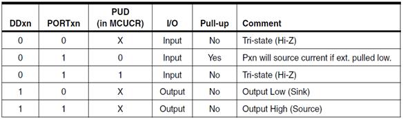
Configure I/O Port Pins
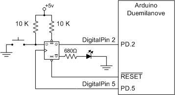
As shown in the Protoshield schmatic, Port D pin 5 is wired to the positive edge triggered clock input of our D flip-flop. Port D pin 2 is wired to the Q output of the D flip-flop. To make your code more readable, add the following mnemonic equates after the include (.INCLUDE ) assembly directives at the top of your program.
Within the initialization section (reset) of your program configure these two Port D pins wired to the debounce flip-flop as defined by Table 13-1 in the ATmega328P data sheet.
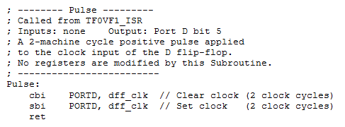
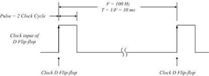
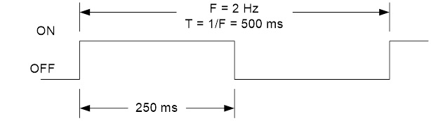
To create a 4 Hz low pass filter, we will pulse the clock input of the D flip-flop every 250 ms. Not coincidentally, this is the same frequency at which the direction LED blinks (4 Hz).
Add the following subroutine in the Support Subroutines section of your program.
Next, add a call to the Pulse subroutine (rcall Pulse) after the call to Delay in the Main loop. Now let’s see if everything is working.
Green LED Test Sequence
When you press the reset button, the Green LED on your board should turn on for a short period of time before your program starts running at which time it should turn off. Try it now! If it does not momentarily turn ON, then most likely we are looking at a problem with the circuit.
IC is not getting Power
It the IC is not getting power trace back (see detailed schematic) to find what parts if any have power. From this information you can hopefully find out where the problem is. For example: power pin is not soldered. Next check if after reset the /Q1 output is high (pin 6).
IC is getting Power
If it is getting power you need to check if reset was applied. Using the multi-meter verify that the CLR input (pin 1 1CLR) to the 74ALS74 is swinging between 5v and 0v (approximately) when you push and release the reset button.
Reset (CLR input) is not toggling
It the CLR input is not being toggled, then trace back (see detailed schematic) to find out why button pin is not pulled up (resistor not wired correctly) or signal is not getting to the IC.
Yes, Green LED turns ON…
Once your program starts running the Green LED should turn off. If it does not then most likely Port D pin 5 is not being clocked. Did you remember to call pulse from your main loop? If pulse is being called correctly, then modify the pulse subroutine to toggle one of the discrete LEDs.
When you press the button the Green LED should turn ON, after a slight delay and then turn OFF when the button is released. A failure here most likely means that the button is not connected to the input of the flip-flop. Using your multimeter, verify at the input to the D flip-flop that when the button is pressed the voltage swings to 0 v.
External Interrupt Service Routine (ISR)
Section 11 “Interrupts” of the ATmega328P data sheet provides detailed instructions on how to configure the ATmega 328P processor to support external interrupts. We will be using External Interrupt Request 0 (INT0) to interrupt the processor whenever the user presses the button wired to our debounce circuit, the output of which is wired to Port D pin 2 (see proto-shield schematic).
Configure External Interrupt 0 registers EICRA and EIMSK
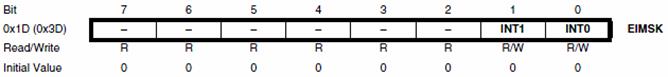
Let’s begin by looking at what the conditions need to be to trigger an external interrupt. Specifically, we need to tell the processor which external interrupt is enabled and if the interrupt is triggered based on the level or edge of the input signal. The ATmega 328P supports two external interrupts which are individually enabled by setting bits INT1 and INT0 in the External Interrupt Mask Register (Section 12.2.2 EIMSK).
Figure 1: External Interrupt Mask Register
For External Interrupt 0 bits ISC01 and ISC00 of the External Interrupt Control Register (Section 12.2.1 EICRA) determine if the interrupt is triggered based on the level or edge of the input as defined in Table 2 “Interrupt 0 Sense Control”.
Figure 2: External Interrupt Control RegisterTable 2: Interrupt 0 Sense Control
We want to trigger our external interrupt on “The falling edge of INT0” so we want to set ISC01:ISC00 = 102 (the colon simple means these two bit together). Insert the following code in the reset section of your program to configure the External Interrupt Mask Register (EIMSK).
The location of this code snip-it is not important as long as it is in the reset (before loop label) section of your code. What is important is the location of the “Set the Global Interrupt” Flag (I) in SREG (Status Register) instruction (sei) . As a general rule, I enable interrupts (using instruction sei) as the very last step in the initialization process – just before the label loop. For example:
sei // Global Interrupt Enableloop:
Add INT0 to Interrupt Vector Table
After enabling external interrupt zero (sbi EIMSK, INT0) and all interrupts (sei), if an interrupt is asserted on the INT0 line then the processor will automatically jump to location 0x0002 (INT0addr) in the Interrupt Vector Table (IVT) located in Flash Program memory. Before it jumps to this location it will also save the current location of the Program Counter (PC) so it can return to the interrupted program.
Add a jump to our INT0 Interrupt Service Routine at this location in the IVT.
Table 11-6 “Reset and Interrupt Vectors in ATmega328P” provides a complete list of all 26 interrupts supported by our microcontroller. With respect to the above code, notice that our Interrupt Vector Table now implements one of these interrupts. At this time you may want to read the Owner’s Manual located near the end of the lab.
Write INT0 Interrupt Service Routine
As discussed in the Owner’s Manual we only want to display the room in the maze that the bear is entering after the button is pressed. We will implement this change by adding a third state (S2) to the FSM designed in part A of the lab. To transition to this third state, a new variable named walk will be set to true. Once defined and initialized, the ISR will set this variable.
Step 1: Add an assembly directive equating the text string “S2” to the number 0b10
.EQU S0 = 0b00 // state 0.EQU S1 = 0b01 // state 1.EQU S2 = 0b10 // state 2
Step 2: After this equate, add an assembly directive equating the text string “true” and “false” to 0xFF and 0X00 respectively.
 room: .BYTE 1
 dir: .BYTE 1
 next_state: .BYTE 1 // FSM next state
 walk: .BYTE 1
Step 4: Initialize the variable
 clr r16
 sts dir, r16
 sts room, r16
 sts next_state, r16
 sts walk, r16 // do not walk
Step 5: Add the following external interrupt service routine, which updates the variable room. Place just after the main loop.
 rjmp loop

 ; ---- External Interrupt 0 Service Routine -----------------
 ; Called when a falling edge is asserted on the INT0 pin (PIND2)
 ; INTF0 flag automatically cleared by AVR on vector interrupt
 ; SRAM Variable room is modified by this ISR
 INT0_ISR:

 push reg_F
 in reg_F,SREG
 push r16

 ldi r16, true
 sts walk, r16

 pop r16
 out SREG,reg_F
 pop reg_F
 reti
Software Implementation of a 3-State Finite State Machine
Now lets add a third state (S2) to the 2-state FSM built in the part A of the lab.
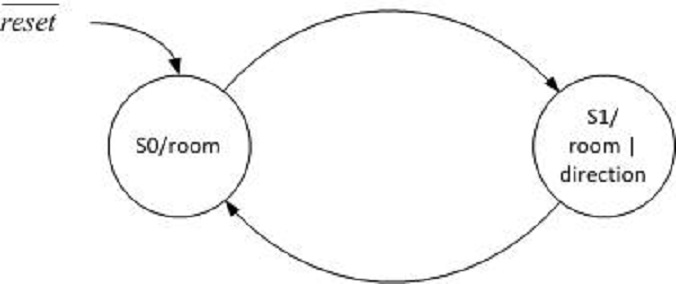
Figure 3: 3-State FSM
We have just written the ISR to set the variable walk to true when the user presses the programmable button on the protoshield. As seen in FSM state transition diagram above, when walk is true, we want to transition to our new S2 state. Within S2 we want to set the walk variable back to false, takeAStep, and display the room only.
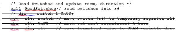
Step 1: Move the code that assigns the switches to the room in the main loop to a new subroutine named takeAStep.
loop:call ReadSwitches // read switches into r7 mov r17, switch // move switch (r7) to temporary register r16 cbr r17, 0x0F // mask-out least significant nibble swap r17 // swap nibbles sts room, r17 // save formatted value to SRAM variable room // dir = switch & 0x03; mov r17, switch // move switch (r7) to temporary register r16 cbr r17, 0xFC // mask-out most significant 6 bits sts dir, r17 // save formatted value to SRAM variable dir. : rjmp loop :TakeAStep:push r17 call ReadSwitches // read switches into r7 mov r17, switch // move switch (r7) to temporary register r16 cbr r17, 0x0F // mask-out least significant nibble swap r17 // swap nibbles sts room, r17 // save formatted value to SRAM variable room pop r17 ret
Step 2: Update the next state decoder for state S1 to reflect the FSM
state_S2:cpi r20, S2 // test is optional for this lab brne end_switch // output decoder write the code to set walk to false, TakeAStep, and DrawRoom// next_state decoder write the code to set next_state equal to S1
Lesson Learned
By Nicholas Lombardo (F’14)
I have helped several people with debugging and one thing that I saw repeatedly was people using “lds r16, false” when they should be using “ldi” since false is equated to a constant 0x00. I assume that what ends up happening is that the compiler loads the register at ext. I/O address 0x00 which, if I recall correctly, is r0.
It can be a little confusing the first time around, but using the bug usually manifests in the program looping between state 1 and state 2 and is very hard to catch unless you know what you’re looking for. The first time I helped someone with this, it took about an hour of scouring the code and back-stepping until we found out the fix which was literally changing a single letter.
Test Your Program
You may upload your program to quickly check to see if it works. An updated Owner’s Manual is provided in the next section to help you step through the maze. Follow the steps in the Owner’s Manual to check the operation of your program. I would be surprised if your program works the first time; if it does not, you will need to simulate the steps defined in the Owner’s Manual. See “Simulation and Debugging” for help here.
Owner’s Manual
Follow these steps to navigate a maze.
Figure 4: Bear at the Entrance of the Maze
Download and run the program. The bear should be shown at the entrance of the maze – an empty room. The direction you want the bear to walk should also be blinking. Specifically, toggle switches SW1 and SW0 to tell the bear to walk north. You will not be using switches SW3 or SW2 in this lab – set them both to 0 (no turn).
Using the maze from Lab 1 as a guide and following the direction indicated by the seven segment display, input the next room the bear will be entering by toggling switches SW7 to SW4. The room LEDs on the 7-segment display should not be updated as you toggle the switches.
Push the button to provide the bear with the directions. You should now see the room you entered in step 3 displayed along with the direction in which the bear was told to walk (note: the direction may not be visible if it is obscured by a wall).
Toggle switches SW1 and SW0 to tell the bear which way to walk next. The blinking direction LED on the 7-segment display should be updated as you toggle the switches.
Repeat steps 2 through 4 to verify the basic operation of the program. You do not need to guide the bear all the way to the forest.
Simulation and Debugging
Enter and verify the basic operation of the program using AVR Studio. Remember, before you run any program you should know what values will be contained in the effected registers. Tip: Within the simulation window expand the PortD, EXTERNAL_INTERRUPT, and TIMER_COUNTER_1 items in the I/O View window to easily initiate an interrupt and to view the operation of your program. To initiate an interrupt you can simulate the button being pushed by toggling PortD PIND bit 2.
Stop program execution . In the I/O View window select PORTD. In the bottom window check PIND bit 2. This simulates pressing the button down.
Single step the program once or twice. Then uncheck PIND bit 2. This simulates releasing the button. The external interrupt is configured to trigger on the falling edge of the input signal.
Single step the program at least twice to initiate the call to the interrupt. You should now see the program counter go to the INT0 address (INT0addr) within the interrupt vector table (IVT).
Note: Unlike Timer Interrupts you cannot initiate an external interrupt by directly setting the external interrupt flag.
After you have verified the basic operation of your circuit, and your INT0 interrupt service routine (ISR), upload and run your program on the Arduino.
Lab Demonstration
You may be asked to…
Simulate an external interrupt
Demonstrate using AVR Studio that the SRAM variable room is updated every time the button is pressed.
Demonstrate the correct operation of your program as defined in your “Owner’s Manual” found at the beginning of this lab.
Design Challenge – Timer 0 (4 Points)
You can skip these sections if you are happy receiving a passing grade (“C+”) on the lab. If you want to receive a good or excellent grade you will need to accept the challenge.
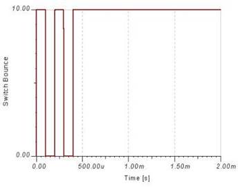
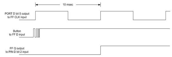
You may have already discovered that if you press the button quickly enough the new room is not updated. The cause of this intermittent behavior comes from the current design clocking the D flip-flop every 250 ms (4 Hz). To solve this problem, apply what you learned in Lab 4A and lecture to call the pulse subroutine every 10 msecs (100 Hz). This time is fast enough to catch the button being pressed, while also filtering out any switch bounce. There are two methods for implementing this, which are modifying the existing delay subroutine or to utilize the overflow interrupt.
Here are some tips to help you translate your code from Lab 4A’s Timer 1 to Lab 4B’s Timer 0
Calculate Timer 0 Load Value
While Timer 1 is a 16-bit timer, Timer 0 is only an 8-bit timer. This introduces a number of problems. First, an 8-bit timer can not generate a 10 msec delay with the clock divided by 64. Fortunately, it can with the clock divided by 1024. Next, instead of subtracting by 216 = 65,536, you now will want to subtract by 28 = 256. Next, you will be reloading TCNT0, a single 8-bit register and not a 16-bit register (8 bit registers TCNT1H and TCNT1L).
Setup and Timer 0 Polling
Probably the most subtle difference between the two timers is the mapping of the registers. All Timer 1 Registers (TCCR1B, TCNT1H, TCNT1L, and TIMSKI) are outside the I/O address space of the ATmega 328P. Consequently, you used the Store to SRAM (sts) assembly instruction for accessing these registers. In contrast Timer 0 Registers TCCR0B and TCNT0 are within the I/O address space of the ATmega 328P, while TIMSK0 remains outside the I/O address space. The main consequence of this mapping is the need to use the I/O output (out) instruction, in place of the sts instruction when writing to registers TCCR0B and TCNT0.
Do not forget to remove your call to the pulse subroutine from the end of the main loop.
For the first method of modifying the existing delay subroutine, consider how the polling routines work. We still require the 250 msec delay for the transition between states in the main loop. During that time, the program is unable to check the status of Timer 0. It is not possible to call one polling routine during another. There will be some modification required to generate the 250 msec delay and call the pulse subroutine every 10 msec.
For the overflow interrupt method, determine the registers that need to be modified and figure out the additional code that needs to be added.
Lab 4 Deliverable(s)
STOP Read the Lab READ ME document contained in the Labs Folder. Be absolutely sure you have followed all instruction in the “Lab Formatting” section of this document. Points will be deducted if you do not follow these instructions. You have been warned.
Make sure your lab notebook is up to date. Follow the guidelines provided in the “Lab Notebook” section of the Lab READ ME document.
Make sure you have read and understand the “Plagiarism” section of the Lab READ ME document, especially if you are repeating the class.
All labs should represent your own work – DO NOT COPY.
Table of Contents
Basic Lab
a. Main Program (Title Block, Initialization (setup), Main Loop (loop))
b. Interrupt service routine INT0_ISR
c. Subroutines (TakeAStep, Delay, and Pulse) in that order.
In the lab you are going to write an interrupt service routine to respond to the push-button debounce circuit included with your proto-shield and shown here. Increase Resolution
Figure 1: Debounce Circuit
Question 1 After reset is applied and before clock is asserted, will the LED be ON or OFF. Explain your answer.
Question 2 Assuming the current into the D input of the Flip-flop is negligible, what current, if any, would flow through the pull-up resistor wired to the button when the button is pressed?
The introduction of the push-button on the proto-shield brings us, for the first time, in contact with the real world. Here are two real world problems that came up during the original design of the circuit shown in the schematic. My first design simply wired the button and resistor to the input of the micro-controller.
Rise and Fall Times
Between logic 0 and logic 1 there is an undefined region. Electrical signals have a finite period to transition through this region, technically known at rise and fall times. For some micro-controller inputs this can be no more than 20 nsec. If this specification is violated the input may start to oscillate causing havoc within the device. Next, the input circuits of MOS devices, like our AVR micro-controller, can be characterized as capacitive in nature (can be modeled to the first order by a capacitor). For some inputs this capacitance can be as great as 10 pF (pico = 10-12). Now, let us assume an external pull-up resistor of 10 KΩ. Given this information we come up with a “back of the envelope” calculated time constant (RC) of 100 nsec. Clearly, we have a problem. I solved this problem by adding a TTL device between the switch and the micro-controller. The input of the 74ALS74 Dual D-Flip-flop can be characterized as resistive in nature (can be modeled by a resistor). Combined with a pull-up resistance (10 KΩ) the input problem is ameliorated. The output of the 74ALS74 TTL device goes directly to the input of the AVR micro-controller solving the transition problem. This new faster circuit however introduces its own problems as discussed in the next section.
Debounce
When you press a button, its contacts will open and close many times before they finally stay in position. This is known as contact bounce. Depending on the switch construction, this mechanical contact bounce can last up to 10 or 20 milliseconds. This isn’t a problem for lamps, doorbells and audio circuits, but it will play havoc to with our edge-triggered interrupt circuitry.
Figure 2: Switch Bounce
With respect to the waveform above, all our switch debounce solution has to do is filter out these transitions. This can be done in several ways. For some simple electrical solutions visit http://www.patchn.com/Debounce.htm. For our solution, I added a D flip-flop which is clocked at a frequency less than 50 Hz (1/20 milliseconds). This digital circuit acts as a low pass filter blocking the AVR interrupt circuitry from responding to any of these additional edges. Another solution, is to disable the external interrupt during the switch bounce time. This solution acts again like a low pass filter, and thus removes the need to the external D Flip-Flop; however, it does not address the rise and fall transition time concern.
Question 3 In this question you are going to modify the waveform diagram with inputs D and CLK of the Flip-flop and output Q as shown below. The clock input (CLK), shows two (2) clock cycles with a period of 10 milliseconds each. The D input labeled “Button to FF D input” shows the switch initially pressed and the input at logic zero. The button is released just before the first clock edge. The output of the debounce circuit for these input conditions is shown as “FF Q output.”
To investigate how the debounce circuit works, I want you to move the point at which the button is released (the bouncing part of the waveform) in the Figure below. Move the switch bounce so its occurs somewhere relative to the leading edge of the clock signal labeled “Port D bit 5 output to FF CLK input”. The exact phase relationship of the switch bounce to the clock edge is left to you. Based on these two inputs (Button and CLK) to the D Flip-flop redraw output signal Q. Vertical lines
Figure 3: Filtering Switch Bounce
Question 4Using what you have learned in class and from chapter 10 in your textbook, answer the following:
Your program has two interrupts enabled in addition to reset: external interrupt request 0 (INT0), and timer/counter 1 overflow interrupt (TIMER 1 OVF). While the program is in the ISR for INT0, the INT0 flag is set. What will happen? Explain.
If both interrupt flags set at the same time, what program address (the actual number) will be loaded? Hint: see ATmega328P IVT.
What should be the last instruction in the ISR?
Question 5INT0 in an ATmega328P is connected to a normally high switch. It is required that the value of PORTB0 should toggle when any logical change occurs.
1. Initialize INT0 to generate an interrupt when the pin has any logical change:
______ r17, 0x_____
______ EICRA, _____
2. Enable external interrupt 0:
______ EIMSK, _____
3. What other instruction is needed to enable INT0?
What Should I Turn In?
Turn in the following material three pages. Make sure all your original work is in your Lab Notebook. All written material must be typed or very neatlydone in ink. Once again please do not copy.
Page
Title page with the pre-lab number, your name and picture, today’s date, and the day your lab meets.
The problem statements (remove explanatory text) and solutions to all pre-lab questions. Circle and/or highlight your answers. Make sure all your original work is located in your lab notebook.
With the introduction of subroutines, things are now more organized; however, it is still difficult to distinguish between a room segment and a direction segment. In this lab, you will solve this problem by writing a software polling routine using Timer 1 to toggle the direction LED on and off with a period long enough for you to see it blink (2 Hz).
Figure 1: Direction Segment Waveform
What is New?
Here are some of the new concepts you will be exploring in this lab.
Implementing a Finite State Machine (FSM) in software.
Working with Timers and Counters
No new assembly directives or instructions are introduced in this lab.
Create the Lab 4A Project
If you are using a lab computer I would recommend erasing everything in Drive D and using this area for our project. Do not forget to save often. At the end of the lab do not forget to save to your Flash drive.
Open AVR Studio and create a new Project named Lab04 (see Lab 1 for detailed instructions)
Copy over spi_shield.inc, testbench.inc, and upload.bat from Lab03.
Open the upload.bat file in notepad (right-click edit) and change the file name from Lab03.hex to Lab04A.hex
Copy the text in Lab03.asm into Lab04A.asm
Update the information in the title block.
Build your project and verify you are starting with zero errors and zero warnings.
Build pseudo_instr Include File
At this point your program has become fairly large and hard to manage. To simplify things a little you are going to make a new include file to hold the pseudo instructions that you completed in the last lab.
In AVR Studio open a new file (File – New File)
Cut and Paste the following material from your Lab03B.asm file over to this new file.
a. Subroutines TurnLeft, TurnRight, TurnAround, RightPaw, Leftpaw, and Hitwall
b. If you like you can also move or simply delete the test routines for these subroutines (TestHitWall, TestRightPaw,and TestLeftPaw)
c. Move and/or delete any assembly directives (.EQU, .DEF) associated with these subroutines. If you have done the basic lab sequence, you probably did not write any new assembly directives.
Save the file with the name pseudo_instr.inc
Assemble and upload to your board. Verify that your program is still working.
Make a backup copy of your project folder so you can return to a working program if needed.
Lab Reset
Now that you know that your pseudo instructions work you no longer need the test bench code created in Lab 3 (A and B).
Download and unzip my Lab03.zip
Open the Lab03.asm file (File – Open) in AVR Studio.
Select All the text in Lab03.asm (CTRL-A, CTRL-C) and copy over your to your Lab04A.asm file (CTRL-A, CTRL-V).
Close the Lab03.asm file (you no longer need it).
In your main program (Lab04A.asm) add the INCLUDE assembly directive to include your new pseudo_instr.inc file. .INCLUDE “spi_shield.inc” .INCLUDE “testbench.inc” // DrawDirection and DrawRoom .INCLUDE “pseudo_instr.inc” // Pseudo Instructions
Assemble and upload to your board. Verify that your basic program is still working. Specifically, you can draw a room and direction.
Delay
In the initialization (reset) section of your code set the Timer 1 prescale value and start Timer 1. You may also want to initialize the TCNT1H:TCNT1L register pair.
call InitShield
; Set prescale and start Timer/Counter1 ; Add your code to initialize Timer Counter 1 (TCNT1) from the pre-lab ; and add comments explaining the code.
ldi r16,(1<<cs11)|(1<<cs10) // prescale of 64
sts TCCR1B,r16 // Clock Select Bit Description
The C++ bit-wise left shift operator
The C++ bit-wise left shift operator << is used to move a one (1) into a specified bit location within a byte. In the first half of the expression an 8-bit value is built with the CS1 bit 1 set to 1 ( 0b00000010).In the second half of the expression an 8-bit value is built with the CS1 bit 0 set to 1 ( 0b00000001). The C++ bit-wise or operator | is used to combine these two bytes to form the byte to be stored in register r16 (0b00000011).
Add the Delay subroutine from your answer to Question 3 in your pre-lab.
; ————————————- ; ——- Support Subroutines ——— ; ————————– ; —— Delay 250ms —— ; Called from main program ; Input: none Output: none ; no registers are modified by this subroutine Delay:
push r16
wait:
Place your commented polling routine from pre-lab question 3 here pop r16 ret
Testing Delay using the Proto-shield
You have now added a subroutine to generate a delay of 250 ms, but how will you know it really works? In this section we will add the toggle code you wrote in the prelab.
Define a new byte variable named next_state. Later in the lab you will be generating a 2-state Finite State Machine (FSM), at which time this name will hopefully make sense.
This is the third variable we have saved in SRAM, so let’s review what is happening. The .DSEG assembly directive tells the AVRStudio assembler that we are going to be talking about the Data Segment (DSEG). The .BYTE assembly directive tells the AVRStudio assembler that we want to reserve N bytes of RAM whose starting address should be associated with the specified name. In this example the variable name is next_state and the number of bytes to be associated with this name is 1.
We will be using variable next_state to tell us if the direction bit is currently ON or OFF. A good programming practice is to initialize all variables on reset. Within the reset section of your program clear variable next_state.
clr r16 // your comment here sts next_state, r16
Call Delay
Place your code to toggle next_state from the prelab (Question 4) at the beginning of the loop section of your program as shown here.
loop:
call ReadSwitches // read switches into r7 /* Read Switches and update room, direction, and turn */
Block of code to update variables room and dir based on switch values.
Include your code to blink the discrete LEDs and your call to the Delay routine at the end of the loop section after drawing the room.
/* Room Builder */ lds r24, room // calling argument room is placed in r24. rcall DrawRoom // translate room to 7-seg bits mov spi7SEG, r24 // return value is saved to 7 segment display register call WriteDisplay // display the room
/* update discrete red LEDs */
Insert your solution to prelab question 5 here
call WriteDisplay rcall delay // insert a delay of 250 ms rjmp loop
Verify that your new code is working before proceeding to the next section. You may need to simulate, in which case be sure and follow the debug tip here and keep the TIMER_COUNTER_1 window open.
You may notice that the LEDs do not change as quickly as before. This is a by-product of polling which blocks all other instructions from being executed until the 250 ms delay times-out. You will have a chance to correct this problem by accepting the design challenge.
Debug Tip 1
Waiting for a 16-bit Timer/Counter to time-out in a simulator even when you are simply running the simulation (not single stepping the program) can take a long time.
You have two ways you can set the overflow flag. The simplest is to set a breakpoint anywhere in your loop and once the program is stopped manually set the overflow flag bit.
Figure 1: Timer Counter 1
You can also speed things along during testing by short-counting the first time-out and resetting the count in the Delay subroutine, by initializing the timer/counter to a relatively high value as shown here.
DO NOT FORGET TO PUT THE ORIGINAL TIMER VALUE BACK ONCE YOU HAVE IT WORKING ON THE SIMULATOR.
Once you know the Delay routine is working you can test the remainder of your code by simply commenting out your call to delay.
// rcall delay // insert a delay of 250 ms
DO NOT FORGET TO UNCOMMENT THE CODE BEFORE YOU UPLOAD THE CODE TO YOUR BOARD.
Blink Direction Segment
Software Implementation of a 2-State Finite State Machine
You are now ready to blink the direction segment. This is the first time in the labs that the output of the display is dependent on what has occurred in the past. In your digital logic design class you learned that to solve this problem you must design a Finite State Machine (also known as Sequential Logic). In our case we only need to design a two state FSM to solve the problem.
Figure 2: 2-State FSM
Technically, we will be implementing a Moore FSM. Which means that the output is completely defined by the current state and is independent of the inputs. As shown in Figure 2 on reset the FSM enters state S0 and only the room segments are displayed. On the next clock cycle the FSM unconditionally moves from state S0 to state S1. The term clock cycle is not the same as the 16Mz clock running the ATmega328P. Instead it is the software “clock” of our FSM. Specifically, one “clock cycle” is defined by the program looping back (rjmp loop) to the start of the loop section of code. Now, when the FSM enters state S1 both the room and direction segments are displayed. In this way, as the FSM continuously goes from state S0 to state S1 and then back again every 250 ms, the direction segment is turned on and then off – it “blinks.”
Following is a block diagram of our Moore FSM.
Figure 3: 2-State FSM Block Diagram
Here is how our FSM would translates into C++ (see Arduino Script Lab04A).
state = next_state;
switch (state){ state S0:
{ // output seg7 = drawRoom(room); // next state decoder next_state = S1; break; }
state S1:
{ // output seg7 = drawRoom(room) | drawDirection(dir); // next state decoder next_state = S0; }
}
Notice that the Output decoder and Next state decoder blocks have equivalent software sections defined for each state. As Figure 1 illustrates and the code shows, the variable next_state is simply assigned to the other state in its corresponding “next state decoder” block of code. The output blocks of code also mimic their FSM state diagram counterparts.
In order to simplify how we represent the states, add the following two lines to the very beginning of the lab after the title block.
.EQU S0 = 0b00 // state 0 .EQU S1 = 0b01 // state 1
Where Do I Add My FSM?
Once completed your FSM will be replacing your current next_state logic and incorporating room and direction builder (DrawRoom, DrawDirection) within the output blocks of the FSM. Delete your simple blink logic done in the last section.
loop:
call ReadSwitches // read switches into r7 /* Read Switches and update room and direction */
Incorporate this code into the output blocks of your FSM.
/* Room Builder */
lds r24, room // calling argument room is placed in r24.
rcall DrawRoom // translate room to 7 segment bits mov spi7SEG, r24 // return value, the room, is saved to 7 … call WriteDisplay // display the room
/* Draw Direction */ lds r24, dir // calling argument dir is placed in r24. rcall DrawDirection // translate direction to 7 segment bit mov spi7SEG, r24 // Display DrawDirection …
Block of code to update discrete LED variable spiLEDS
// writeDisplay(leds,seg7); call WriteDisplay rcall Delay // insert a delay of 250 ms
rjmp loop
Build Your FSM
Use the underlined code above with your FSM implementation. I have started the translation process from the C++ code to assembly to help you get started.
loop:
call ReadSwitches
// dir = switch & 0x03; mov r17, switch // move switch (r6) to temporary register r17 cbr r17, 0xFC // mask-out most significant 6 bits sts dir, r17 // save formatted value to SRAM variable dir.
/* Read Switches and update room and direction */ // room = switch >> 4; mov r17, switch // move switch (r6) to temp register r17 cbr r17, 0x0F // mask-out least significant nibble swap r17 // swap nibbles sts room, r17 // save formatted value to SRAM variable room.
/* Moore FSM */ // state = next_state; lds r20, next_state // r20 = current state // switch (state) // { // state S0: state_S0:
cpi r20, S0 brne state_S1
add your output and next state decoder :
rjmp end_switch // break
state_S1:
cpi r20, S1 brne
add your output and next state decoder :
rjmp end_switch // break
end_switch:
Block of code to update discrete LED variable spiLEDS // writeDisplay(leds,seg7); call WriteDisplay rcall Delay // insert a delay of 250 ms rjmp loop
When completed you should have only one call to WriteDisplay as shown here.
Upload and/or Simulate Your Completed FSM
Upload and/or simulate your completed FSM. Both discrete red LED 7 and direction LED of the 7 segment display should be blinking. The most significant 4 switches should be able to build a room as before.
So what should happen if the bear is headed into a wall? Specifically, the segment direction bit is also a wall segment bit in the room. In this instance, the 7-segment LED should always be ON (the bear cannot walk into a wall).
If you are still not sure how your program should behave, you can always open and upload the provided Arduino Script Lab04A.ino within the Arduino IDE.
[/av_textblock]