[av_textblock size=” font_color=” color=” av-medium-font-size=” av-small-font-size=” av-mini-font-size=” admin_preview_bg=”]
In order to find out how heavy the robot could be while still staying on the board, it was necessary to find out how much force a magnetic solution could be expected to generate. Once this force was known, the frictional force equation could be used in conjunction with the experimental value for the coefficient of friction to extrapolate how much mass the robot could consist of before the magnets fail to provide enough force to keep the robot on the board.
[/av_textblock]
[av_heading tag=’h1′ padding=’10’ heading=’Theory’ color=” style=” custom_font=” size=” subheading_active=” subheading_size=’15’ custom_class=” admin_preview_bg=” av-desktop-hide=” av-medium-hide=” av-small-hide=” av-mini-hide=” av-medium-font-size-title=” av-small-font-size-title=” av-mini-font-size-title=” av-medium-font-size=” av-small-font-size=” av-mini-font-size=”]
Stuff we will put here woohoo…
[/av_heading]
[av_textblock size=” font_color=” color=” av-medium-font-size=” av-small-font-size=” av-mini-font-size=” admin_preview_bg=”]
The pull force of a magnet is proportional to its maximum energy product which is defined to be the flux density (B) multiplied by the field strength (H). In the CGS system, flux density is measured in Gauss, and field strength is measured in Oersteds. In the SI system, flux density is measured in Teslas, and field strength is measured in Amps per meter. The flux density (B) can be thought of as a material’s response when an outside field (H) is applied. When a material is magnetized, a magnetic field is applied to it with an electromagnet or a permanent magnet. As the material is exposed to an increasingly large external field, the magnet becomes saturated and its flux density approaches a maximum value asymptotically. When the applied field is removed, the flux density of the magnet reduces to its residual flux density, not its original value of zero. This non-linear response is called hysteresis. If a new field is applied to the magnet in the opposite direction of the original with increasing magnitude, the flux density of the magnet will eventually reach zero. The strength of the field that needs to be applied to negate the field of the magnet is called the coercivity of the magnet and describes its resistance to demagnetization. After the magnitude of the applied field exceeds the coercive field strength, the magnet’s field follows the same B versus H curve as the original magnetization process, but rotated 180° about the origin. The whole path that the magnet’s flux density and field strength follow throughout this process is called the BH curve or a hysteresis loop. Each material has its own unique BH curve which must be measured experimentally. An example of a BH curve can be seen below in Figure 1.
Figure 1. The BH curve of a hypothetical material
Point 1 to point 2 shows the path of magnetization as the material is saturated by the applied field. Point 2 to point 3 shows what happens when the applied field is removed and the flux density drops to the residual flux density of the material. Points 3 to 4 show the relation between the fields when an oppositely oriented field is applied to the magnet. The curve crosses the H axis when the applied field is equal to the coercivity of the material. The behavior of the magnet is described by its curve in quadrant 2, because this quadrant describes how the material responds to applied magnetic fields after it has been magnetized. Accordingly, the maximum energy product of a magnet is defined to be the place in the 2nd quadrant where the product of B and H is maximized. This value is shown graphically in Figure 2.
Figure 2. The maximum energy product of a hypothetical material
The pull force of a material is directly proportional to its maximum energy product, so using a magnet with double the maximum energy product will double the pull force. The ratings used for high performance magnets are typically in Mega Gauss Oersteds. Grade N35 neodymium magnets have a maximum energy product of 35 MGOe, meaning that they provide approximately 10 times the pull force of a typical ceramic magnet of the same size and shape because a ceramic magnet has an energy product of 3.4 MGOe. A table of energy products is shown below in Table 1.
Magnet Type
Max Energy Product (MGOe)
Neodymium
35-52
SmCo 26
26
Alnico 5/8
5.4
Ceramic
3.4
Flexible
0.6-1.2
Table 1. The max energy products of 5 magnet materials
K&J Magnetics provide a pull force calculator on their website which claims that the grade N35 magnets used in E-racer’s design should provide a pull force of 20.4 newtons of force at a distance of 0 mm from the board and a pull force of 2.58 newtons at a distance of 3 mm. The whole force curve can be seen in Figure 3 below.
Figure 3. The theoretical force curve of the neodymium magnets used in E-racer
Because the coefficient of friction was determined in the experiments described in the last blog post, if a number of magnets and a distance from the board are chosen, the resultant force can be used in conjunction with the frictional force equation to solve for a maximum mass of the robot that the friction of the treads will support. In the case of the E-racer, the original plan was to use 6 magnets at 2.5 mm. This would result in a total theoretical force of 19.75 newtons. Plugging into the frictional force formula gives Equation 1.
Equation 1. Plugging the theoretical magnetic force and coefficient of friction into the frictional force equation
Converting from newtons to kilograms gives Equation 2:
Equation 2. Converting from weight to mass using Newton’s second law
This meant that the theoretical maximum mass that the robot could be was 1.1 kg, which should have been more than enough.
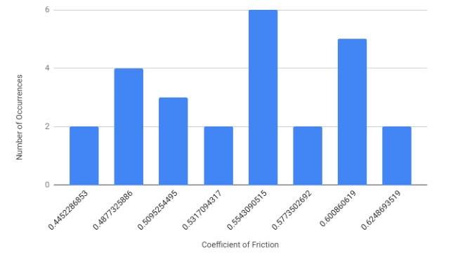
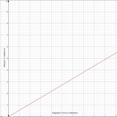
In order to verify that the theoretical force is accurate, an experiment was devised. A spring scale was attached to one of the neodymium magnets with tape and the magnet was placed on a whiteboard. The magnet was pulled off of the whiteboard and the force required to remove the magnet was recorded. This process was repeated with multiple sheets of paper between the magnet and the board. The total thickness of the sheets was measured with calipers each time and an experimental force curve was recorded by plotting the force at each distance. This graph can be seen in Figure 4.
Figure 4. The experimental force curve
The force that the magnets created in the experiment was significantly less than the theoretical value. This was probably due to the thickness of the steel in the whiteboard. The theoretical pull force value was generated under the assumption that the steel was significantly thick and would not be saturated, meaning that it was not a limiting factor when determining the magnetic attraction with the magnet. According to K&J Magnetics’ article, the magnetic force that a magnet makes scales linearly with the steel plate’s thickness up to a point where the plate is no longer saturated. At this point, increasing the thickness of the plate no longer has an appreciable effect on the pull force. Figure 5 shows the magnetic force of a magnet as a function of the thickness of a steel plate to which it is attached. The graph shows how the force is linear in one region and becomes almost constant after a threshold thickness is surpassed.
Figure 5. The pull force as a function of plate thickness for a hypothetical magnet
K&J suggests that for the plate not to have a significant effect on the force, the plate thickness should be two to three times the largest dimension of the magnet. The largest dimension of the magnets implemented in E-racer was the 12 mm diameter. This means that if the steel used in the whiteboard is less than 36 mm, the thickness of the steel will be a limiting factor, and the pull force will be less than the the theoretical value. After the actual magnetic pull force was known, the true maximum weight of the robot could be extrapolated. Plugging the experimental pull force and the coefficient of friction into the frictional force equation as well as converting to mass from force gives Equation 3:
Equation 3. Solving for frictional force and maximum mass
which means that the actual maximum mass of the robot can be with grade N35 neodymium magnets mounted at 2.5 mm from a CSULB whiteboard in contact with Tamiya brand treads will hold a mass of 505 grams before sliding.
[/av_textblock]
[av_textblock size=” font_color=” color=” av-medium-font-size=” av-small-font-size=” av-mini-font-size=” admin_preview_bg=”]
This post outlines the importance of choosing the right magnet type for the given application and how to solve for the frictional force given the coefficient of friction and the normal force.
[/av_textblock]
[av_textblock size=” font_color=” color=” av-medium-font-size=” av-small-font-size=” av-mini-font-size=” admin_preview_bg=”] The reason torque is useful is because it relates the length of a torque arm to the force applied at the end of the arm. Specifically for the E-Racer, the motors need to apply enough torque to the sprockets that the force applied to the board is enough to lift the robot.
[/av_textblock]
[av_heading tag=’h1′ padding=’10’ heading=’Theory’ color=” style=” custom_font=” size=” subheading_active=” subheading_size=’15’ custom_class=” admin_preview_bg=” av-desktop-hide=” av-medium-hide=” av-small-hide=” av-mini-hide=” av-medium-font-size-title=” av-small-font-size-title=” av-mini-font-size-title=” av-medium-font-size=” av-small-font-size=” av-mini-font-size=”]
Stuff we will put here woohoo…
[/av_heading]
[av_textblock size=” font_color=” color=” av-medium-font-size=” av-small-font-size=” av-mini-font-size=” admin_preview_bg=”] The definition of torque is the force applied perpendicular to a torque arm multiplied by the length of the arm. This means that in the SI system, the standard derived unit of torque is the newton meter. In simpler terms, when a force of one newton is applied perpendicularly to a lever that is one meter long, one newton meter of torque is applied at the fulcrum of the lever. The general formula for torque is:
Equation 1
Where ? is torque, F is the force applied to the lever, and L is the length of the lever. In the example outlined above, the force applied at the end of the lever caused the torque, but the formula can also be used to find how much force a given amount of force applied to a torque arm would apply tangent to the curve traced by the end of the arm. Additionally, the formula can be used to solve for the length a lever needs to be to to make a given torque relate to a given force. In the case of the E-Racer, the torque is a specification outlined by the manufacturer of the motors, and the task at hand was to define the radius of the drive sprocket that would give enough force to the treads to climb the wall. This rearranged formula solving for F gives:
Equation 2
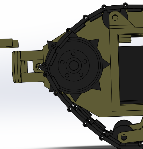
Referring to this equation, it becomes clear that the smaller the sprocket radius is, the more force can be obtained from the motors. The limiting factors for the sprocket radius were that they needed to surround the gearboxes of the motors in order to keep the tank proportional to the original Goliath 302 tracked mine. This meant that reducing the radius too much would cause the sprocket’s walls to be too thin, or worse yet, cause them to grind against the gearboxes. The Pololu micro-metal gearmotor’s axle face dimensions are 10 mm x 12 mm, meaning that the maximum distance that the gearbox extends in the radial direction from the axle is:
Equation 3
This means that the inner radius of the sprocket needed to be at least 8 mm if not more in order to clear the gearbox. Additionally, the sprocket needed to be thick enough to withstand stress without fracturing or warping. The final constraint on the sprocket was that the outer radius of the sprocket needed to conform to the Tamiya tread to ensure that there would be a whole number of teeth, and that they would be spaced properly. The ratio of teeth to radius in mm was determined by measuring the Tamiya brand sprockets and counting their teeth to be one tooth per millimeter of radius. This meant that if the outer radius was not a whole number of millimeters, the circumference of the sprocket would not accommodate a whole number of teeth with the proper spacing. The final design for the sprocket was chosen to have an outer radius of 11 mm and an inner radius of 9 mm to ensure that there would be enough clearance around the gearbox, and that the sprocket would be thick enough to withstand the forces being applied to it.
This meant that the effective torque arm radius was about 11.2 mm, because the total distance from the axis of rotation to the force being applied was the outer radius of the sprocket plus the height of the teeth of the sprocket. At this point, the projected mass of the robot was 200 grams. This meant that the robot’s motors together needed to produce:
Equation 4
of torque. To confuse things, most motor manufacturers list the torque of their motors in kgmm. One kgmm describes the amount of torque required to lift a one kilogram mass with a lever arm of one millimeter. The unit relates mass to length instead of force to length, but assumes that the force acting on the mass is caused by gravity at earth’s surface. This means that force to mass conversions can be done easily by dividing by the acceleration of gravity: 9.8 m/s2. Recalculating the torque value in kgmm gives:
Equation 5
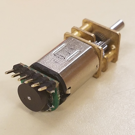
This means that the motors chosen for this project each need to produce at least 1.12 kgmm of torque in order for the E-racer to be able to climb the board. In order to meet this criterion, the low power, 210:1 gear ratio, Pololu micrometal gear motor was chosen. The datasheet for the motor claimed that it was capable of creating 1.12 kgmm of torque while drawing 62 mA, which was within the projected allotment of current capable of being supplied by the battery.
Also it should be noted that the formula used for torque in this post is a simplified version. Technically, torque is the cross product of the force and distance. This definition simplifies to the formula described above when the force applied is perpendicular to the length of the torque arm because the definition of the cross product gives:
Equation 6
Additionally, this simplified formula makes the assumption that there is only one force acting on the sprocket which is applied tangent to the curve of the sprocket. In many cases, a force is distributed along an interval of distances from the axis of rotation. In these types of cases, it is necessary to use calculus to sum all of the torque by integrating the product the force as a function of distance by the corresponding distance. Symbolically this looks like:
Equation 7
These definitions are not used in this post, but it is necessary to outline the scope of this document and when the methods used in it are applicable. If the force being applied is not perpendicular to the radial distance, the cross product definition should be used, and if the force is not applied at one distance, but a range of distances, the integral definition should be used.
[/av_textblock]
[av_textblock size=” font_color=” color=” av-medium-font-size=” av-small-font-size=” av-mini-font-size=” admin_preview_bg=”] In order to get the proper speed from a motor, it is important to supply it with enough power. This statement seems obvious, but it is important to understand the relationship between electrical power and mechanical power when choosing a motor and or battery. The simplified equation for the power of a motor is:
Equation 8
where P is power, I is current in amps, V is voltage in volts, ? is torque in newton meters, and ? is the angular velocity in radians per second. Obviously, this model is rudimentary as it neglects the energy lost in the conversion of electrical energy into mechanical energy, but it is useful for getting a quantitative estimate of how much torque and speed a motor will produce. In reality, the efficiency of most electric motors is 20-30%, which makes getting an accurate estimate difficult without testing or sophisticated simulation. A better way of estimating the performance of a motor is to use the data sheet provided by the manufacturer. The following diagram shows speed, current, efficiency, and power of a hypothetical motor as a function of torque.
Figure 1. Power, efficiency, current, and speed as a function of torque
From observation, it is clear that the current scales proportionally to the torque, and the speed scales with a negative slope. What is less obvious is why the power is maximized in the middle of the graph. To explain this, it is necessary to take a look at a model of a motor as a circuit.
Figure 2. The circuit equivalent of a motor
The motor acts like a resistor, inductor and voltage source in series. The voltage source is called the back EMF of the motor and increases with the rotation speed of the motor. So for a fixed voltage, as the current increases, the speed decreases, and so does the back EMF. This means that as the current increases, the voltage across the EMF decreases, and the product of a line of positive slope and a line of negative slope produces a concave down parabola as shown in Figure 1. Specifically, the power consumed by multiplying the current by the voltage across the EMF defines the power input, and the speed multiplied by the torque defines the power output. The efficiency of the motor is then the power output over the power input. Because the voltage is constant, the power input scales linearly with the current, and therefore the efficiency can be defined by dividing the output power by the current and the supply voltage. Visually, the shape of the efficiency curve can be sketched by simply dividing the orange curve by the red line. This curve is helpful when choosing a motor, because the motor will perform the best if the load it drives is near the peak of the efficiency curve.
[/av_textblock]
[av_textblock size=” font_color=” color=” av-medium-font-size=” av-small-font-size=” av-mini-font-size=” admin_preview_bg=”] The method used to test the torque of the motors involved using a luggage scale, a sprocket designed to fit the motor’s axle, and bit of nylon string strong enough to hold the expected tension. The motor was adhered to a table with tape and the sprocket was placed on the axle with the string tied around the circumference of the sprocket. The hook of the luggage scale was tied to the other end of the string, and the motor was then run and the tension force applied to the string was recorded with the scale. It is important to note that the motor should not be allowed to stall during this process; it should continue to rotate at a rate above 30 RPM at all times to avoid damage. Multiplying the force applied to the string by the radius of the sprocket gives the amount of torque generated.
[/av_textblock]
[av_textblock size=” font_color=” color=” av-medium-font-size=” av-small-font-size=” av-mini-font-size=” admin_preview_bg=”] A slightly better test would be to have the motor act as a winch and lift increasingly large masses. The torque could be calculated similarly to the method above, by multiplying the weight of the masses by the radius of the sprocket or reel and the RPM of the motor could be counted by hand or with a tachometer. Gathering the RPM as a function of torque and measuring the current with an ammeter would provide enough information to create a graph similar to the one in Figure 1, which should be more than enough to know how a motor will behave when operating.
[/av_textblock]
[av_textblock size=” font_color=” color=” av-medium-font-size=” av-small-font-size=” av-mini-font-size=” admin_preview_bg=”] This post is meant to outline the theoretical underpinnings of how torque is defined, how the definition of torque can be used to find how much force a motor will apply, and how the performance of a motor can be calculated using its data sheet.
[/av_textblock]
[av_textblock size=” font_color=” color=” av-medium-font-size=” av-small-font-size=” av-mini-font-size=” admin_preview_bg=”]
This blog post illustrates and explains the iterative design process under the engineering method; throughout the project E -Racer, a line following robot that moves on a whiteboard. Designing a product under strict requirements posed a challenge to my group and myself personally because we had to meet the satisfaction of the customer. The iterative process; however, reveals the overall improved and exceptional product that can be made. As Manufacturing and Design Engineer, I learned to adapt the iterative design process, and through the engineering method I was able to complete our desired product, of a scaled down version of a Goliath 302 tank, that climbs a whiteboard.
[/av_textblock]
[av_heading tag=’h1′ padding=’10’ heading=’Initial Designs’ color=” style=” custom_font=” size=” subheading_active=” subheading_size=’15’ custom_class=” admin_preview_bg=” av-desktop-hide=” av-medium-hide=” av-small-hide=” av-mini-hide=” av-medium-font-size-title=” av-small-font-size-title=” av-mini-font-size-title=” av-medium-font-size=” av-small-font-size=” av-mini-font-size=”]
Stuff we will put here woohoo…
[/av_heading]
[av_textblock size=” font_color=” color=” av-medium-font-size=” av-small-font-size=” av-mini-font-size=” admin_preview_bg=”]
Beginning the semester, we had intentions of making a robot that would travel along the whiteboard surface. I took some time to rapid prototype some models using miscellaneous parts that I had and was lent. As seen from the pictures I designed two different robots, that were small enough and light enough to attach and move on a vertical surface. I noticed that the treads provided good friction to grab and move the robot along the whiteboard. With these 2 design iterations, I was trying to see what size and weight I needed to have to be able to stick to the wall and move, as well as test the friction of rubber tires and tracks for a tank, as part of the engineering method. Eventually, I settled on the Goliath tank body to perform this task. I was demonstrating the engineering method performing these tasks and I learned from my mistakes.
Referencing the actual Goliath 302 Tank and previous semester’s Goliath design, I started from scratch with my own version at a smaller scale than the previous semester, Generation 5. This was in tie to the requirement of being smaller in size and being able to still fit a 3 dot board. I did not use previous solid works files because I had difficulty with SolidWorks program not having used it in a while; however, by the time I got to Proto 2 I picked up the pace and improvement was seen.
Figure 3: Testing Goliath Design from the previous semester with magnets
Figure 4: Sketch of the top view of Goliath (Gen 6) DesignFigure 5: Scaled Measurement of Goliath tank
In order to meet the requirements of having a scaled-down version of the real Goliath 302 Tank, I had to make some calculations as seen from the picture above. To do this I referenced the length of the 3 Dot Board to accommodate for the real dimensions of the tank (L:1.5 x W:0.85 x H:o.56 meters). Once I found the scale ratio indicated by LRATIO , I was able to find the new scaled down dimensions of the tank. It resulted in a scale factor of 0.63, which was smaller than the previous generations.
Figure 6: Initial Assembly of Scaled Prototype 1
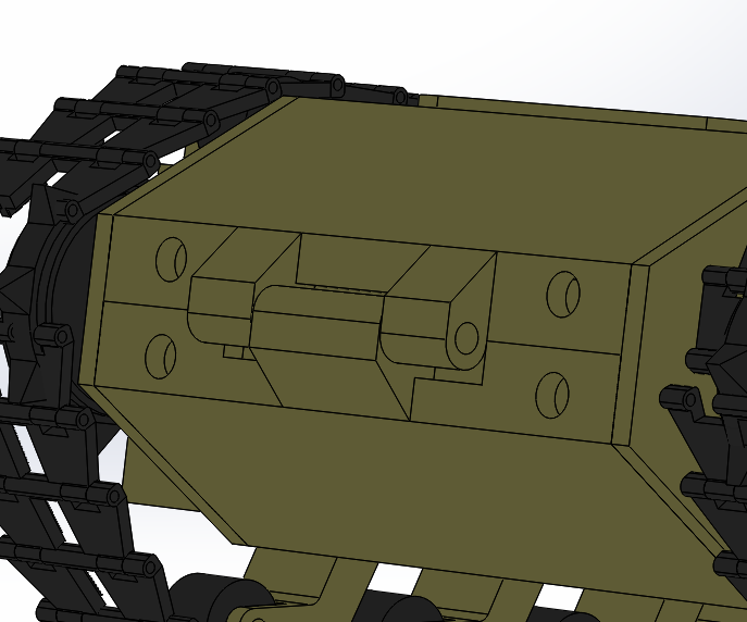
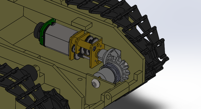
Motor gearbox sticks out of motor housing to accommodate for smaller width tank and have the 3 dot slide in and touch side walls. Design for hollow sprockets came from Sojourner design. With this design, we can have a smaller width tank. Essentially, the goal was to have a small enough inner width to flush fit a 3 dot board into.
Learned from previous rapid prototypes:
Goliath proved successful in traction and weight
Big wheels and small wheels for the second concept combined caused tipping when it climbed the wall
All 4 big wheels design was too heavy, and the motors used provided very little torque to climb the wall
Sometimes using tools or parts that you have available don’t pan out as well; however, well-documented info and previous material from Goliath was very helpful
Design Flaws of Proto 1:
Track widths too small (scaled but not proportioned)
Learned to make the scale slightly bigger and make 3dot width the scale reference as opposed to the length as seen from calculations when finding the scale factor.
At this point, finding the point of interest where the tank is smaller than the previous semester and smallest overall, while still retaining proportion, from this new smaller scale.
Figure 8: Choosing the set scale for Prototype 2Figure 9: Miscellaneous calculations, measurements, and SolidWorks designing for Prototype 2Figure 10: Assembly Layout view of parts for Prototype 2Figure 11: Motor Housing and BaseFigure 12: Hollow Sprocket Drive Wheel
I worked alongside MST: Jeremy Anderson, to create the new hollow sprocket drive wheels. We had to find the ratios of (number of teeth) to (sprocket radius in millimeters) referencing back to the Tamiya set of sprocket wheels provided from Professor Hill. We discovered that they had a ratio of (1 tooth) per (1mm radius). Measuring the radius was done using a caliper. We can see from the picture provided above, how the drive wheel encases the gearbox of the motor. This design allows for the teeth to align with the small tension arms that hold the small idler wheels.
Modifications from previous design:
Side panels extended to compensate for track width
Open slot below motor housing to allow 3Dot board female headers to connect to custom PCB
Created big idler wheels and drive (sprocket) wheel
Sprocket drive wheel design:
Teeth were created in reference to Tamiya toy set wheels
Made them hollow so that motor gear housing can sit inside
Design flaws of Prototype 2:
3 Dot insert was not established and unclear
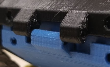
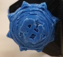
3D print did not come out very well, not good for testing
[av_textblock size=” font_color=” color=” av-medium-font-size=” av-small-font-size=” av-mini-font-size=” admin_preview_bg=”]
Up to this point in the iterative design process, the picture below denotes the several models of Goliath tanks. Starting from far left is the Goliath Gen 5 from the previous semester, then a paper model I made of the proper dimensions for Prototype 3 (final scale); finally, the print of Prototype 1. They are side by side to see the size difference. Although I made the final scale as seen from Figure 13 slightly bigger than Prototype 1; it still remains smaller than the previous generation.
Figure 13: Comparing size differencesFigure 14.2: Tension system sketchFigure 14.3: Tension system 3D model
Figuring out quick access 3Dot design, ended up going with door panel design came up from previous talk about cupboard like design to slide 3 dot in and out, so I decided to make something that will hold the 3 dot in place and keep from falling out as well as be able to put and take the 3 dot in and out
The following design came to mind:
Figure 15: Determining 3Dot insert and quick accessFigure 16: Model of real Goliath 302 tank
It is important to notice that I moved away from the traditional design of clamping the top panel and bottom panel together as previous semesters did. However, this design is quite inaccurate. I learned later on when I added aesthetic features to the tank during Prototype 4 stage and referenced the following image from Figure 16 that the Goliath tank actually does have a door panel. To my luck, and keeping the most realistic attributes of the tank, the door panel proved successful.
Figure 16.1: Door panel closedFigure 16.2: Door panel open
Another key point to mention form this new 3DoT insert and quick access assembly is that now the overall tank can be seen as 3 main parts. The two side panels and the top panel which includes the motor housing and door panel; as opposed to previous designs where 4 main parts were required to assemble the robot: the top panel, bottom panel, and two side panels. I was able to meet this realization because of the implementation of the 3DoT acting as an external base of the tank, which was inspired by the Paper Bot design.
Figure 17: Miscellaneous calculations and measurements for Proto 3
Another important feature discovered in this prototype is the application of bearings to spin and attach the big idler wheels too. The following designs were made:
Figure 18.1: Big Idler Wheel AssemblyFigure 18.2: See through of Big Idler attachment to bearing
I also had the task of making custom treads for this robot. However, it proved to be difficult after talking with Jeff and Professor Hill at AoSA. Jeff’s reasoning was that the printer had to have small enough resolution to be able to print the small material that holds each individual tread piece that makes up the whole track. Because the robot is so small, making tracks smaller than Tamiya proved difficult. Below is the design I made of the custom treads with the help of MST Jeremy, referencing back to the Tamiya treads and cutting off the sides to make them look thinner. I started with one tread piece, measuring out the Tamiya tread, and once one tread piece was complete, I created a plane down the center so that I can make a circular pattern with a radius of 40mm; which was the measured circumference of the wheel assembly on the side panels.
Figure 19: Custom Tread 3D design model, using Tamiya as reference
The following image shows the print of Prototype 3 from PolyJet material, it was a very clean print and with this prototype we were able to do some small tests of climbing on the whiteboard.
Figure 20: Prototype 3 tank, PolyJet print
Modifications from the previous prototype:
Door panel (quick access to 3 dot board) this was designed this way because it serves as quick access to USB and switch, as well as a holder of the 3DoT to keep from falling out when in a vertical motion
3Dot insertion inspired by the Paperbot design
Top panel and motor housing are 1 piece
Added the bearing capture which will turn the big idler wheels with less friction
Side tension mechanism design, but not in 3Dprint at that time when presenting CDR
Design flaws of Prototype 3:
Magnet plate needs to be placed closer to whiteboard surface; around small idler wheel level
Need a method to hold the big idler wheels to side panels through the bearing (use of bolts and nuts required)
Need to hollow outside panel blocks, make the robot-heavy
Need to find hardware and apply for small tension arms and wheels
Motor housing did not keep motors steady, they would tilt (redesign needed)
The model needs aesthetic modification (make look like an actual tank)
Tension system needs to be tested (design but no print at the time)
Figure 21: Prototype 4 TankFigure 22: Modification of Big Idler to bearing attachmentFigure 23: Bearing and Big Idler Assembly view
Bearing installment was altered from this design to have the bearing slide into the pocket seen from the inside of the side panel and remain flush so that the door panel will hold the bearing in place and keep from falling out, where only the outside trace of the whole bearing is being held stationary, only inner race is freely moving.
Figure 24: Side View of Prototype 4
In the picture above, we can finally see the tension system on a print and works as its intended to.
Figure 25: Frontal view of Prototype 4 tank
The two picture below show the door panel features, when closed it keeps the 3 Dot Board from falling out and provides quick access to the USB port and On/Off Switch. When open we are able to slide the 3 Dot Board in and out of the robot.
Figure 26: Back view of Prototype 4 tank (door closed)Figure 27: Back view of Prototype 4 tank (door opened)
Modifications from previous design:
Added support on the tension arms because the previous prototype broke off one of the small tension arms
Pulled bottom row of tension arms out more towards the ground to move wheels away from side panel rectangular piece, because they were rubbing from Prototype 3
Added nut captures to hold the nut in place on the small tension arms for the bolt axle
Added artistic touch
Fixed the motor housing keep the motors from wobbling (as noted from before)
Fixed big idler wheel and bearing installment (after talking with Jeff and Professor Hill)
Fixed the magnet plate attachment to allow variability with height away from white board and match ride height when tension system is in effect
[av_textblock size=” font_color=” color=” av-medium-font-size=” av-small-font-size=” av-mini-font-size=” admin_preview_bg=”] To conclude the semester, we have now reached the final design, after much iterative tasks, to finally reveal a scaled down version of the Goliath 302 Tank: with a quick access and easy insert 3 dot mechanism, low friction big idler wheels, hollow drive wheels, and tension system; where all four of these things I consider the main important key features of this version of Goliath tank.
Figure 28: Final Design for E – Racer (added top hatch door)
As seen from the figure above, I have now completed the aesthetics of the tank by implementing the top door hatch, as well as fix some minor parts such as: the small tension arms (added support), the motor housing (added support).
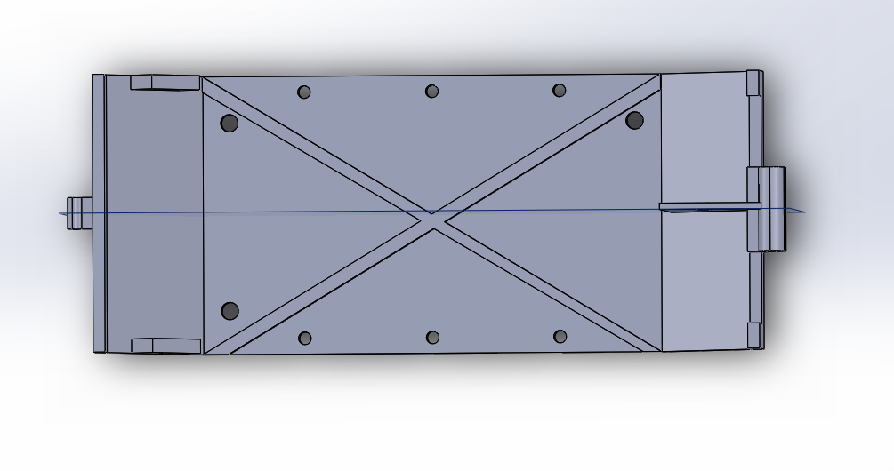
Figure 29: Front view of final designFigure 30: Left side view of final designFigure 31: Back view of final designFigure 32: Right side view of final designFigure 33: Bottom view of final design (magnet assembly)
The figure above shows the magnet plate assembly; held on with 6 bolts and with nut captures at the ends to hold the bolts in place. This design was implemented since Proto 4, to essentially allow the robot to climb on the wall and stay attached to it.
[/av_textblock]
[av_textblock size=” font_color=” color=” av-medium-font-size=” av-small-font-size=” av-mini-font-size=” admin_preview_bg=”]
Through this mechanical iterative design process, I have learned the importance of scheduling as well as why several projects take time. The multiple iterations of prototyping reveal mistakes made as well as improvements. By 3D printing the designs made on Solid Works we are able to test the mechanical aspects of the robot. Also, an important action to take in the design process is to have access to a 3D Printer and make multiple prints immediately, after making modifications. It is also very important to talk with the customer and follow guidelines and requirements to ultimately, achieve a fully operational product.
[/av_textblock]
[av_textblock size=” font_color=” color=” av-medium-font-size=” av-small-font-size=” av-mini-font-size=” admin_preview_bg=”]
This blog post is intended for keeping a record on IR Shield Design and Manufacturing with QRE1113 for 3Dot Board in the process of E-Racer Robot Project in EE-400D Class at CSULB.
The requirements that are going to be met are:
Program Level 1 Requirements:
L1.15 Extensibility is designed into the 3DoT board by way of one 8-pin 100 mil connector located on the front of the board and two 8-pin 100 mil connectors located on the top of the board. By plugging shields into these connectors, the 3DoT board can support a diverse set of robots. All robots shall contain one or more custom-designed 3DoT shields. The 3DoT shield(s) incorporating interface electronics between the 3DoT board and sensors and/or actuators unique to the robot. Surface Mount Technology (SMT) will be employed unless a waiver for through-hole parts is granted.
Project Level 1 Functional Requirements:
L1.1 The E-Racer will drive on horizontal surfaces made of linoleum(classroom floor).
L1.3 The E-Racer shall be able to follow a course drawn on the 12’x5’ whiteboard in a classroom.
L1.4 The E-Racer shall contain a custom designed PCB for a specified purpose (i.e sensor shield).
L2.4.1 The PCB shall contain the IR sensors used for line following.
L2.6.1 The E-Racer shall implement PID control to autonomously follow the line.
[/av_textblock]
[av_heading heading=’IR Shield Design’ tag=’h1′ style=” size=” subheading_active=” subheading_size=’15’ padding=’10’ color=” custom_font=” av-medium-font-size-title=” av-small-font-size-title=” av-mini-font-size-title=” av-medium-font-size=” av-small-font-size=” av-mini-font-size=” admin_preview_bg=”]
Stuff we will put here woohoo…
[/av_heading]
[av_textblock size=” font_color=” color=” av-medium-font-size=” av-small-font-size=” av-mini-font-size=” admin_preview_bg=”]
The software used for the design of the IR Shield was EagleCAD by AutoDesk.
The idea of the circuit design with QRE1113 from SparkFun Line Sensor Breakout – QRE1113 (Digital).
Shown in Figure 6 are the breakout board and its schematics.
Figure 6 Sparkfun QRE1113 Digital Breakout Board: Photo and Schematics [1]
[/av_textblock]
[av_textblock size=” font_color=” color=” av-medium-font-size=” av-small-font-size=” av-mini-font-size=” admin_preview_bg=”]
This board contains one QUE1113 IR Sensor, one 100ohm resistor, one 220ohm resistor, and one 10nF capacitor. It had been proven in IR Sensor Testing process that in order to make the robot to complete the line-following task, four sensors are needed, so the first version of schematics is basically four of above circuits connect together, which will be proven necessary and works well.
Figure 7.1 Schematics of IR Shield Design Version 1
The version 1 PCB board has arranged the components in the board view shown below:
Figure 7.2 Board View of IR Shield Design Version 1
The reason there are two pins on the shield that are not connected to any components is that they will be connected to SCL and SDA header on the 3Dot board (schematics shown below in Figure 7.3), which is not needed for IR Shield design.
Figure 7.3 Schematics of 3Dot Sensor Header [3]For the board design, in order to meet requirements, the goal is to make the shield as small as possible yet meet all functional requirements, so two-layer design is needed to fit all components in a small board. As one able to observe, there are through holes(green circle) in Figure 7.2 to connect some components through two layers. The dimension of the board is determined based on the dimension of the 3Dot board and the robot. The width of the 3Dot is 35mm, so the width of my design should be 35mm or less.
Although the basic schematic design is determined, there are minor mistakes or things that could have been done better, and also, the board design is very messy with wire traces everywhere, along with mistakes made from lack of experience and knowledge.
[/av_textblock]
[av_textblock size=” font_color=” color=” av-medium-font-size=” av-small-font-size=” av-mini-font-size=” admin_preview_bg=”]
After six generations, a lot of mistakes has been fixed, and many designs have been improved.
Shown in Figure 8.1 and 8.2 are the schematic and board view of the final version of IR Shield.
Figure 8.1 Schematics of IR Shield Design Version 7.2Figure 8.2 Board View of IR Shield Design Version 7.2Figure 8.3 Board View of IR Shield Version 7.2, Two Layers with Polygon
Followings are the most of the modifications and arrangements I made from Version 1 and Version 7, along with reasonings.
Table 1: Modifications from IR Shield V1 to V7.2 and Reasons
[av_textblock size=” font_color=” color=” av-medium-font-size=” av-small-font-size=” av-mini-font-size=” admin_preview_bg=”]
Gerber file is generated by click “CAM Processor” on the top of the window-> click “Process Job” at bottom of the pop-up window after check that all necessary layers are included. For ordering PCB board later, set export file to “Export as ZIP” on the top of CAM window. These steps are usually simple for me since everything just stayed default.
[/av_textblock]
[av_textblock size=” font_color=” color=” av-medium-font-size=” av-small-font-size=” av-mini-font-size=” admin_preview_bg=”]
PCB board is manufactured by JLC Electronics from Shenzhen, China. This company manufacture custom designed PCB at a very low price, for me, was 2 US Dollars for 5 PCBs.
I ordered through their website https://jlcpcb.com.
First, enter the basic information: the dimension(35mm x 14mm), and left default quantity(minimum 5)of PCB, default thickness(1.6mm) and default layers(2), then click “Quote Now” to go to the quote page. Figure 9 shows the quote page and all the options JLC offers for manufacturing PCB, along with selections for IR Shield for this project. The ZIP of Gerber file generated earlier should be uploaded at the top of this web page.
Figure 9.1 JLC Quote Web Page [4]This order of IR Shield arrived on the sixth day after placing the order, a picture of the product is shown below in Figure 9.2.
[av_textblock size=” font_color=” color=” av-medium-font-size=” av-small-font-size=” av-mini-font-size=” admin_preview_bg=”]
While waiting for the board, two sets of components for the IR Shield are ordered. The reason for ordering a second set is to make sure there are backups if anything goes wrong during the assembling process.
All components are ordered from Arrow Electronics at https://www.arrow.com. When finding components, it is important to find them in the right value and physical size, which in our case, is 0603. Bill of Material (BOM) of components is made by E&C engineer which can also be automatically generated by Arrow website.
Table 2: Bill of Material (BOM) of components ordered from Arrow Electronics
A problem was found after assembling that the 8-pin header ordered (2PH1R-16-UA) had diameter of is not tight enough when plug into 3Dot to securely stay on it, then according to advice from the project manager to use another type of header shown in BOM in Table 2 in red (PH1RB-09-UA) which has thicker pins, then they are ordered and they worked well.
Assembly is done using regular soldiering iron and soldier. The final product is shown in Figure 10.
[av_textblock size=” font_color=” color=” av-medium-font-size=” av-small-font-size=” av-mini-font-size=” admin_preview_bg=”]
In this blogpost, QRE1113 IR Sensor is used in PCB design.
All requirements are met during the designing process, and the finished PCB board successfully performed reflection reading tasks and worked well in line following tasks.
[/av_textblock]
[av_textblock size=” font_color=” color=” av-medium-font-size=” av-small-font-size=” av-mini-font-size=” admin_preview_bg=”]
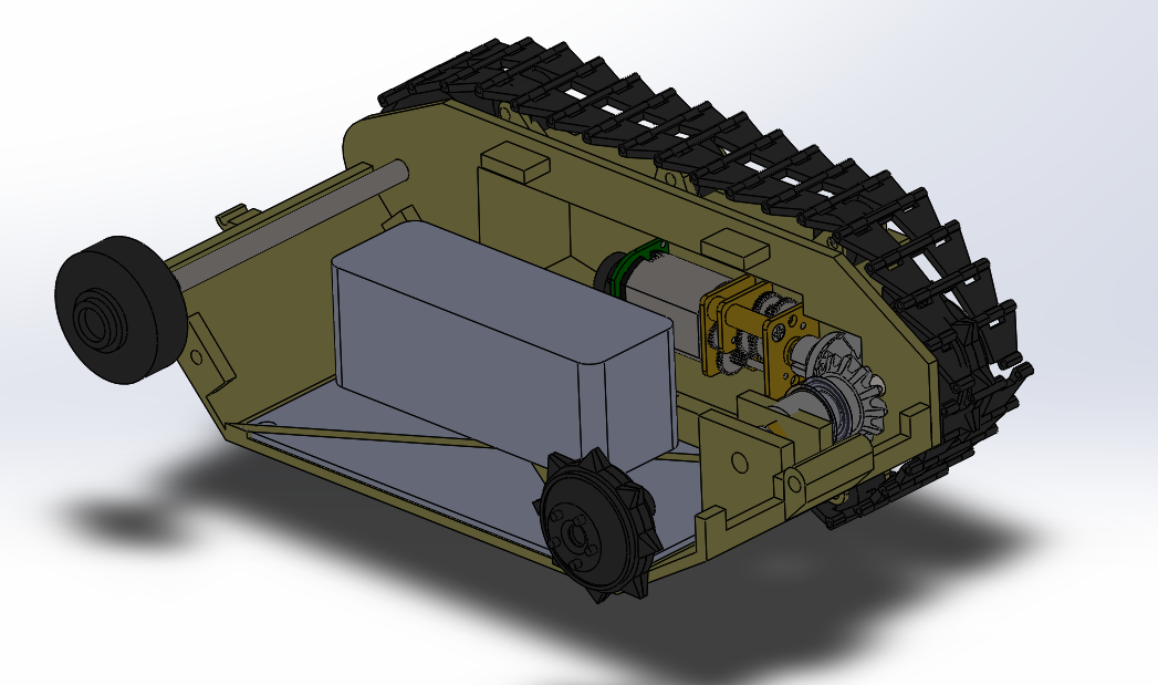
The E-Racer robot is a scale model toy of the 302 Goliath tracked mine. Its compact design includes the Arxterra 3DoT board, micro gear motors, and an IR shield. Assembly is easy for children ages 7+, they only need to plug in the motors and IR shield to the 3DoT, slide it into the chassis, and it’s ready to play. It can be controlled via the Arxterra Mission Control Panel and/or ArxRobot application. There are two play modes: autonomous line following and manual control. It could run on a vertical whiteboard surface or flat horizontal surfaces.
[/av_textblock]
[av_heading tag=’h2′ padding=’10’ heading=’Program and Project Objectives’ color=” style=” custom_font=” size=” subheading_active=” subheading_size=’15’ custom_class=” admin_preview_bg=” av-desktop-hide=” av-medium-hide=” av-small-hide=” av-mini-hide=” av-medium-font-size-title=” av-small-font-size-title=” av-mini-font-size-title=” av-medium-font-size=” av-small-font-size=” av-mini-font-size=”]
Stuff we will put here woohoo…
[/av_heading]
[av_textblock size=” font_color=” color=” av-medium-font-size=” av-small-font-size=” av-mini-font-size=” admin_preview_bg=”] Program Objectives
The Robot Company (TRC) will be debuting its 2019 line-up of toy robots and associated games at the Toy-Invasion 2019 convention in Burbank CA on May 14, 2019. Your team’s assignment is to make the 3D printed and/or laser-cut prototypes to be showcased at the convention, prior to production starting in the second quarter of 2019. The robots will feature our new ArxRobot smart phone application and the Arxterra internet applications allowing children to interact and play games around the world. In addition, the robots should be able operate autonomously in game mode. See game(s) (i.e, mission objectives) assigned to your robot by the Game Division. To decrease electronics cost, interoperability between all TRC robots will be maintained by incorporation of the 3DoT board, developed by our Electronics R&D Section. Modification of downloadable content is limited to software switch setting and robot unique graphics of the smart phone and Arxterra applications. Modifications of electronics are limited to custom 3DoT shields as required by the unique project objectives of your robot. The Marketing Division has set our target demographic as children between the ages of 7 and 13, with a median (target) age of 11. To decrease production costs, please keep robots as small as possible, consistent with our other objectives. As with all our products, all safety, environmental, and other applicable standards shall be met. Remember, all children, including the disabled, are our most important stakeholders. Our Manufacturing Division has also asked me to remind you that Manufacturability and Repairability best practices must be followed.
Project Objectives
The E-Racer project takes the Goliath tank to new heights by giving it the ability to climb whiteboard using neodymium magnets. This generation’s design brings the toy much closer to the real Goliath in terms of scaling and is much smaller than previous generations. It is integrated with the 3DoT board which makes it easy for young kids to set up and play with. It allows them to easily customize the robot and play with it through the Arxterra app or anywhere around the world through the Arxterra control panel.
[/av_textblock]
[av_textblock size=” font_color=” color=” av-medium-font-size=” av-small-font-size=” av-mini-font-size=” admin_preview_bg=”]
The goal of E-Racer is to improve on the Goliath 302 tank design from previous generations. The mission is to autonomously complete a figure 8 course drawn on the whiteboard on the wall. It should also be able to navigate on the floor though remote control via the Arxterra App or control panel while providing a first person POV.
[/av_textblock]
[av_textblock size=” font_color=” color=” av-medium-font-size=” av-small-font-size=” av-mini-font-size=” admin_preview_bg=”]
Level 1 Requirements that are quantitative, verifiable, and realizable. They are created with the customer’s expectations in mind. This allows us to move the design process forward and obtain a clear understanding of what we are trying to accomplish. Level 2 requirements are design solutions the help specify how and how well the robot will perform the functions stated in the level 1 requirements.
[/av_textblock]
[av_textblock size=” font_color=” color=” av-medium-font-size=” av-small-font-size=” av-mini-font-size=” admin_preview_bg=”]
We are in compliance with constraints on the project imposed by The Robot Company (i.e., CSULB) and Project Stakeholders. Specifically, we include University and applicable environmental, health, and safety standards and those safety standards specifically associated with the product (e.g., Children’s Toys).
Applicable Engineering Standards
IEEE 29148-2018 – ISO/IEC/IEEE Approved Draft International Standard – Systems and Software Engineering — Life Cycle Processes –Requirements Engineering.
Federal Communications Commission (FCC) Relevant standards for a product implementing a 2.4GHz radio, FCC Intentional Radiators (Radio) Part 15C, and Unintentional Radiators FCC Part 15B for CPU, memories etc.
NXP Semiconductor, UM10204, I2C-bus specification and user manual.
ATmega16U4/ATmega32U4, 8-bit Microcontroller with 16/32K bytes of ISP Flash and USB Controller datasheet section datasheet, Section 18, USART.
ASTM F963-17, The Standard Consumer Safety Specification for Toy Safety, is a comprehensive standard addressing numerous hazards that have been identified with toys. In 2008, the Consumer Product Safety Improvement Act of 2008 (CPSIA) mandated that the voluntary toy safety standard in effect at that time become a nationwide mandatory children’s product safety rule.
[/av_textblock]
Subcategories: Cost, Extensibility, Interoperability, Maintainability, Quality, Marketability, and Schedule
L1.10 All 3DoT robots shall be constrained not to exceed Cost of $250.
L1.11 All project Schedules shall be constrained to a completion date of Tuesday, May 14, 2019. Project completion includes documentation and materials purchased by or loaned to the project.
L1.12 One of the Economic Factors affecting our robots is return rates. To demonstrate the durability and child-friendliness of our robot a simple drop test from 1.4 meters should be performed. The height is defined by the average height of an average 11-year-old girl.
L1.13 Maintainability: Disassemble and Reassemble of the robot shall be constrained to less than 20 minutes (10 + 10 minutes). Disassembly: The 3Dot board is clear of all other electronic and mechanical subassemblies. All electronic and mechanical subassemblies and associated connectors, sensors, and actuators including motors are disconnected. A functional test of the robot is conducted after reassembly to confirm its functionality. All project may reference a cable tree as well as an assembly diagram as necessary. This requirement is demonstrated/verified on the last day of the schedule. Projects may request a waiver with justification.
Social and Ethical
Subcategories: Accessibility, Aesthetics, and Usability
L1.14 Accessibility by the blind and Marketability of the robots should be implemented/enhanced by a speaker. The speaker shall generate a sound effect consistent with the type of the robot. For example, the Goliath tank would make “track” sounds, the AT-ST sound effects would mimic their Star Wars antecedent.
L1.16 To enhance Aesthetics, the robot shall be designed in such a way that there are no dangling or exposed wires. Connectors will be used between all electronic and electromechanical components. Jumper wires will not be used, ribbon cables are preferred.
L1.17 To enhance Aesthetics, the form factor of a robot modeled on a real or fictitious robot shall be constrained by the original. Goliath should be a scale model of the real Goliath 302 tank.
Manufacturability
Subcategories: Constructability, Size, Weight, and Power (SWAP)
L1.18 Manufacturability of all 3D prints provided by the library’s Innovation Space should minimize the number of files to be printed. Justification should be provided if more than one (1) file is required
L1.19 The Size of the electronics enclosure shall be constrained to be no greater than the 3DoT board, 3DoT shield(s), and associated mounting hardware.
L1.20 Power to all 3D robots shall be provided by the 3.7V RCR123A battery included with the 3DoT board or use of the external battery 2.0mm PH series JST connector located on the 3DoT board. The RCR123A is a Lithium Polymer LiPo battery. All Safety regulations as defined in Section 4.3 Hazards and Failure Analysis of this document shall apply to the shipping, handling, storage, and disposal of LiPo batteries.
Functional
L1.21 All 3DoT robots shall incorporate the 3DoT v8 or v9 series of boards.
L1.22 Software shall be written in the Arduino De facto Standard scripting language and/or using the GCC C++ programming language, which is implements the ISO C++ standard (ISO/IEC 14882:1998) published in 1998, and the 2011 and 2014 revisions. Required exceptions to this standard can be found here.
[av_textblock size=” font_color=” color=” av-medium-font-size=” av-small-font-size=” av-mini-font-size=” admin_preview_bg=”]
Project level 1 requirements define the general tasks that the robot should perform to achieve its objective.
L1.1 The E-Racer will drive on horizontal surfaces made of linoleum(classroom floor).
L1.2 The E-Racer will not fall off of the intended vertical surface (whiteboard) from any orientation.
L1.3 The E-Racer shall be able to follow a course drawn on the 12’x5’ whiteboard in a classroom.
L1.4The E-Racer will contain a custom designed PCB for a specified purpose (i.e sensor shield).
L1.5The course shall be drawn at least the E-Racer’s width, 54mm away from the edge of the board to avoid E-Racer edge collision. (Given by customer)
L1.6The E-Racer mobile application shall have two modes: autonomous and manual
control.
L1.7The E-Racer shall begin moving forward anywhere within the defined start-finish area on the whiteboard.
L1.8The E-Racer shall be smaller than the previous generation 115mm x 85mm x 44 mm.
(Given by customer)
L1.9The E-Racer shall implement a live camera feed in first person POV.
[/av_textblock]
[av_textblock size=” font_color=” color=” av-medium-font-size=” av-small-font-size=” av-mini-font-size=” admin_preview_bg=”]
The level 2 requirements provide design solutions to achieve level 1 requirements.
L2.2.1The E-Racer will implement neodymium magnets on its body to climb the vertical whiteboard.
L2.2.2 The motors shall provide a minimum of 1.01 kg*mm of torque per motor to climb up the whiteboard.
L2.3.1 The course will be drawn with approximately a 15mm black, whiteboard safe marker in a sideways figure 8 total distance approximately 8.7m (342.7 inches).
L2.3.2 The E-Racer should use shaft encoders for speed control.
L2.4.1 The PCB shall contain the IR sensors used for line following.
L2.6.1The E-Racer shall implement PID control to autonomously follow the line.
L2.6.2 The manual control functionality shall be implemented using the Arxterra mobile application.
L2.9.1 The E-Racer shall use the Bluetooth module on the 3DoT to transmit the camera feed.
L2.9.2 The E-Racer will use a periscope to live stream from the ground.
L2.9.3 The E-Racer should provide 2 viewpoints using a smartphone from the
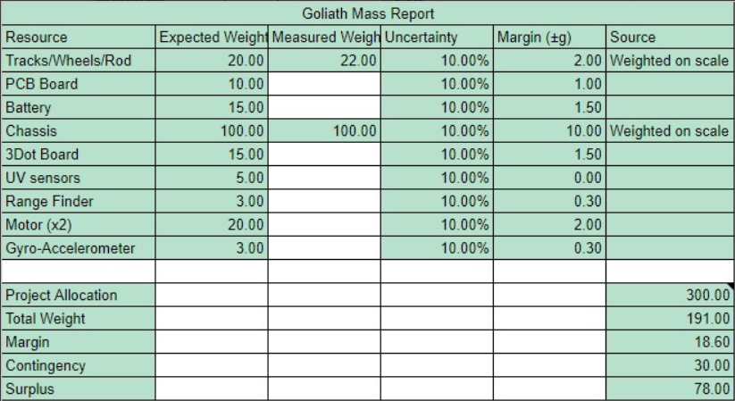
[av_textblock size=” font_color=” color=” av-medium-font-size=” av-small-font-size=” av-mini-font-size=” admin_preview_bg=”] The mass resource report lists the nominal masses of all of the components of the E-Racer as well as the actual measured masses. Additionally, the report documents the total mass of the robot.
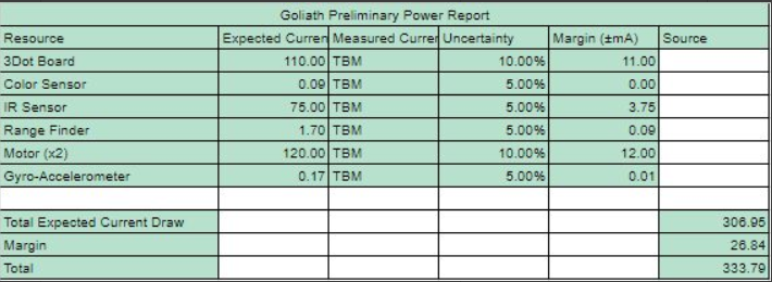
[av_textblock size=” font_color=” color=” av-medium-font-size=” av-small-font-size=” av-mini-font-size=” admin_preview_bg=”] The power resource report shows that neither the Tattu 7.4V battery nor the 3DoT’s battery will die before the E-Racer finishes its mission. It also shows that the batteries will not draw more than their rated current. The current drawn by the motors was calculated assuming that the E-Racer is climbing directly up the wall. The actual current drawn during the test should be less.
[av_textblock size=” font_color=” color=” av-medium-font-size=” av-small-font-size=” av-mini-font-size=” admin_preview_bg=”]
In this section, we will find our work breakdown structure and our product breakdown structure. You will also find our budget and schedule for this semesters project.
[/av_textblock]
[av_textblock size=” font_color=” color=” av-medium-font-size=” av-small-font-size=” av-mini-font-size=” admin_preview_bg=”]
The WBS shows the different tasks each division is responsible for. The Missions Systems and Test are responsible for the System Requirement, Project Allocation, and Verification/Validation. Electronics & Control is responsible for the PCB design, software, and implementation of the 3DoT board. Manufacturing is responsible for designing the chassis for the robot.
Figure 4 – Work breakdown structure of E-Racer
The E-Racer PBS breaks down into primarily three parts: 3DoT, Chassis, and Software. The software includes the code for PID line following, RC mode, and the telemetry for switching between autonomous and RC. The chassis includes the motors, treads, tensioner system, and gears. The 3DoT contains the microcontroller, Bluetooth module, battery, and motor driver.
[av_textblock size=” font_color=” color=” av-medium-font-size=” av-small-font-size=” av-mini-font-size=” admin_preview_bg=”]
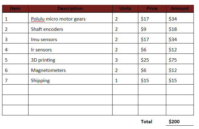
E-Racer’s project cost constraint is $250. Most of the cost of our budget came from 3D printing. There are four print orders of various materials from the CSULB Library Innovation Space. The first print cost $26 because we did not know that each file would be charged a minimum of $5. The other items bought include custom PCB, SMD components, 210:1 micro gear motors, bearings, car mount, 15mm marker, Tamiya treads, and a periscope. The bearings and motors were the second most expensive items per piece. The bearings were used to reduce the friction of the big idler wheels. The micro gear motors were bought for their small size and gear ratio.
[av_textblock size=” font_color=” color=” av-medium-font-size=” av-small-font-size=” av-mini-font-size=” admin_preview_bg=”]
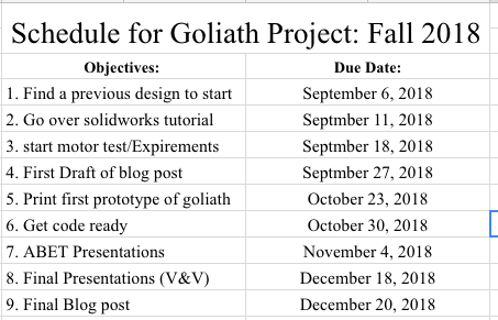
This schedule was made in target process as a timeline view then exported to an excel sheet for this blog.
Figure 7 – Timeline of the schedule converted into excel
[av_textblock size=” font_color=” color=” av-medium-font-size=” av-small-font-size=” av-mini-font-size=” admin_preview_bg=”]
According to the schedule made in Target Process, the percentage complete as of 5/9/19 is 94%.
[av_textblock size=” font_color=” color=” av-medium-font-size=” av-small-font-size=” av-mini-font-size=” admin_preview_bg=”] Referencing the Goliath 302 Tank and previous semester’s Goliath design, Brandon started from scratch with his own version at a smaller scale than the previous Goliath, Generation 5. The project was constrained to be smaller than previous generations and to closely fit a 3DoT board.
[/av_textblock]
[av_textblock size=” font_color=” color=” av-medium-font-size=” av-small-font-size=” av-mini-font-size=” admin_preview_bg=”] To begin our objective, we referenced Generation 3 and Generation 5 SolidWorks files to visualize the model parts that make up the whole tank from Arxterra website and referenced back to the images of the actual Goliath 302 Tank. We found that their scale was not accurate because it was shaped more like a square compared to the real Goliath tank. So the first 2 designs we made, used a new scale size, but to keep it accurately scaled and as small as possible, the treads needed to be smaller. A custom tread was 3D modeled, but Jeff suggested we keep using Tamiya treads. He was concerned that since the model was so small, creating custom treads would require a small enough resolution from the 3D printer to capture the joints where each piece of the tread is joined.
Figure 9 – 3D model of custom sized Tamiya tread
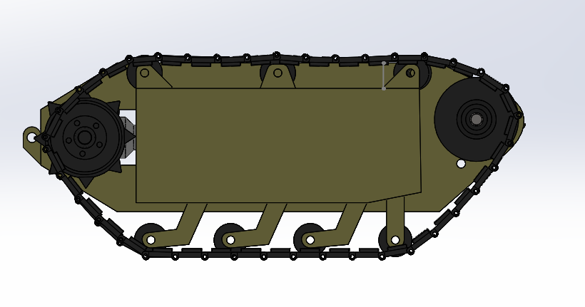
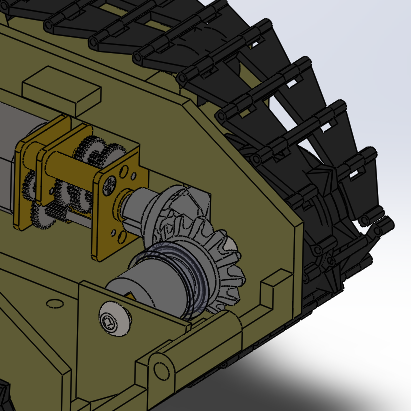
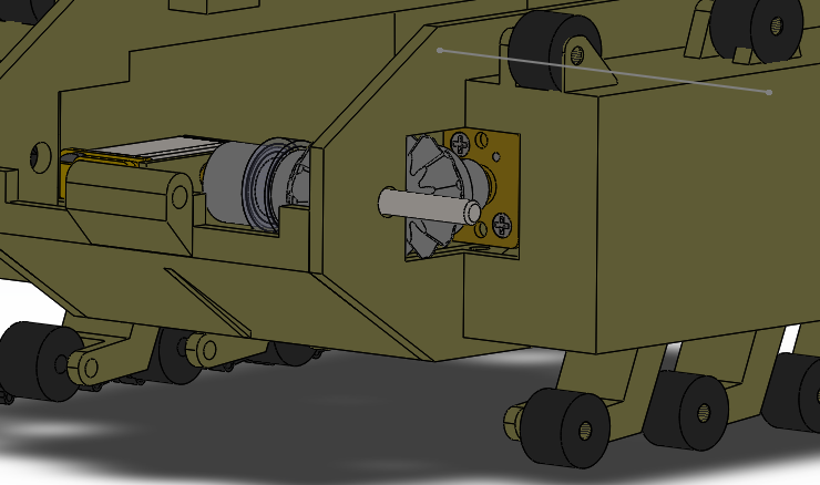
Due to the size constraints, the motors had to stick out of the robot more than previous generations, causing the wheels to not align with the treads. To fix this, we implemented a hollow sprocket wheel design similar to Sojourner, where the wheel would encase the motor allowing the teeth of the sprocket to align with the tensioners.
Figure 10 – 3D model of the motor and sprocket wheel
[av_textblock size=” font_color=” color=” av-medium-font-size=” av-small-font-size=” av-mini-font-size=” admin_preview_bg=”] One problem all the other generations have faced was tensioning. Tamiya treads are only able to be modified in length by set increments since it is an off the shelf product. So in this generation, we introduced a tensioning system for Tamiya treads that slides in a vertical motion to adjust the tension.
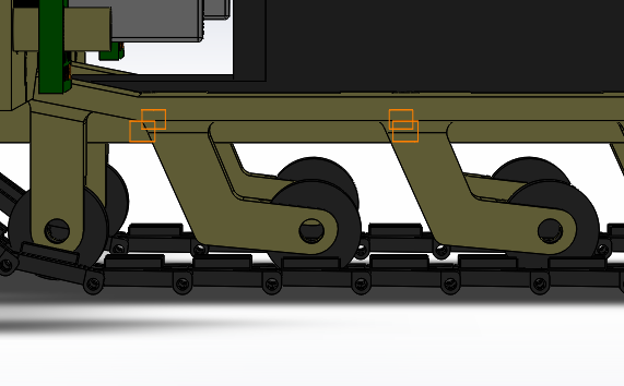
Figure 11 – Tension SystemFigure 12- Back view of a tension system
From the picture above we can visualize how the nut capture insert where the nuts slide into and grab the bolt; when the moving block is pressed against the inner wall of the hollow space.
Also, another issue with the previous semester was not implementing the use of bearings to the extent of reducing the amount of friction present as the big idler wheels are spinning.
Big Idler Wheels with Bearings
Low friction, freely spinning idler wheels
Avoid the use of axles
Figure 13 – Large idler wheel with bearing
As seen from the picture above the bolt slides in from the outside surface of the big idler wheel as indicated by the red arrow and inside a cup-like insert on the side panel a 10mm diameter ball bearing is press-fitted. The end of the bolt is then secured with a nut. The trick to this design was to only make sure the inner race of the bearing is spinning freely, and it was achieved. The nut only grabs the inner race when tightened and on the other side, a small fillet was added to the idler wheel so that a small circular shape will press against the inner race of the bearing.
[av_textblock size=” font_color=” color=” av-medium-font-size=” av-small-font-size=” av-mini-font-size=” admin_preview_bg=”] One of our main objectives was to make the base of the robot so small that it holds just the 3DoT. To achieve this we designed the robot to slide in the 3DoT and have it act as the base of the robot. This helped keep the robot small and played into achieving the requirement to have immediate access to the external connectors. A door panel was created to easily slide in the 3DoT and keep it in place when closed. Also, our customer was unhappy with using wires to hold the small tensioner wheels. So we replaced them with small bolts and nuts.
Figure 14 – Image of the 3DoT sliding into the robot through the door panel
Aside from the changes mentioned above, the other components of the robot are almost the same as the past generations but have been modified to provide more support. The components modified:
Tensioner legs
Added partial nut captures
Reinforced at the base to not break so easily
Motor housing
Added a brace to hold the back of the motor to prevent tilting
Added a small curved wall to prevent the motors from clashing
Figure 15- Motor mount
Cable insert
A small loop to thread the motor wires through to keep them in place is found on the inner wall of the top panel.
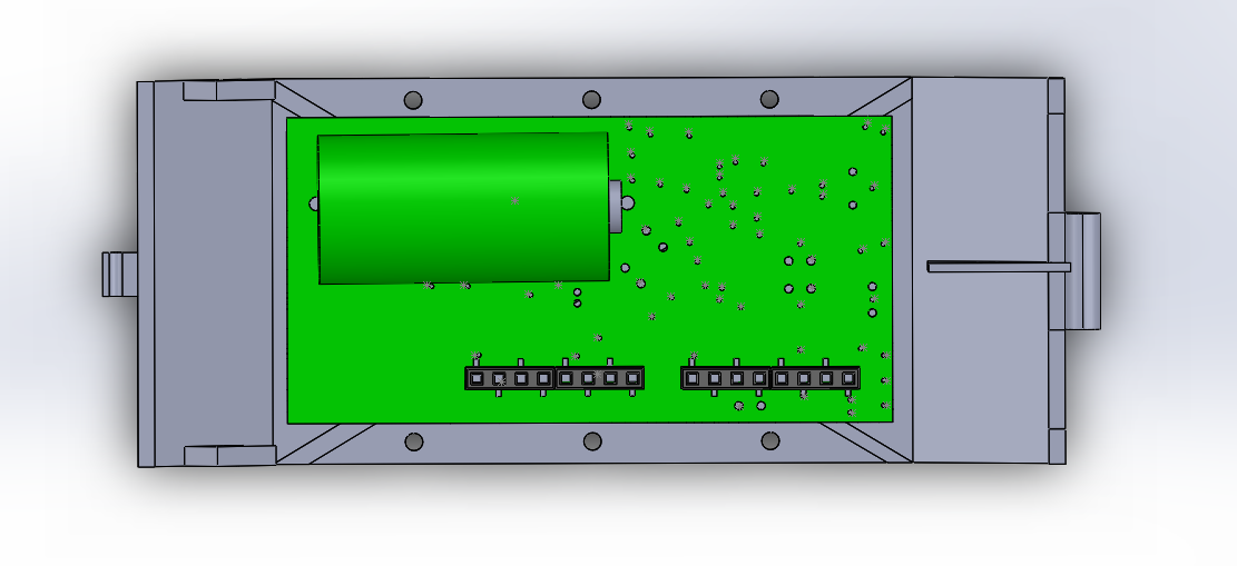
[av_textblock size=” font_color=” color=” av-medium-font-size=” av-small-font-size=” av-mini-font-size=” admin_preview_bg=”] For our final design, we have the hollow sprocket wheels, tensioner system, door panel, magnet plate, and 3DoT base. The hollow sprocket wheel were designed to encase the micro gear motors to allow the robot’s body to stay slim and align with the idler wheels. The tensioner system is designed so that the sides are hollow and the bottom tensioner legs can slide in or out. When the treads are put onto the tank the tensioners are adjusted to the desired height then screwed into place from the sides. The door panel was created to easily slide the 3DoT into the robot and keep it in place. Also when closed, the door panel has an opening that provide immediate access to the external connectors such as the switch and usb port. The magnet plate was made to hold 6 disk magnets with a cap plate to prevent the magnets from accidently pulling itself out due to its strong magnetic force. It hung below the tank with bolts and nuts to make the distance from the board adjustable. It is adjustable because the tensioner system could alter the height of the robot and the magnetic force changes greatly with even the smallest change in distance from the board. The 3DoT base, inspired by the PaperBot, was implemented because it provided a form of secure mounting for the 3DoT and easy access to the external connectors.
For more information check out our design blog post.
[/av_textblock]
[av_textblock size=” font_color=” color=” av-medium-font-size=” av-small-font-size=” av-mini-font-size=” admin_preview_bg=”]
The interface matrix is essentially the same as the 3DoT interface Matrix found in the EE444 lecture but slightly adjusted to match our project. The only cables in our robot are the cables from the motors which connect to the 3DoT board. In the cable tree, the wires curve a bit and are threaded through the cable loop. They are kept long enough so the 3Dot board can be partially pulled out to unplug the motors. There will be two additional cables if the speaker is included.
Figure 17 – Interface MatrixFigure 18 – cable tree
This section provides a systems level look at the software modules employed by 3DoT robots. This section represents a collaborative effort by the system and electronics/control engineers.
Hardware
Software
Personal Computer
Arxterra Control Panel
Smartphone
ArxRobot App
3DoT Board
Arduino and Robot3DoT Library
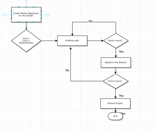
Figure 19 -Command flow chart. The pink box is expanded in the flow chart below it.Figure 20 – Image of the Arxterra App controls
[av_textblock size=” font_color=” color=” av-medium-font-size=” av-small-font-size=” av-mini-font-size=” admin_preview_bg=”]
This section will show the design process of our custom PCB and firmware.
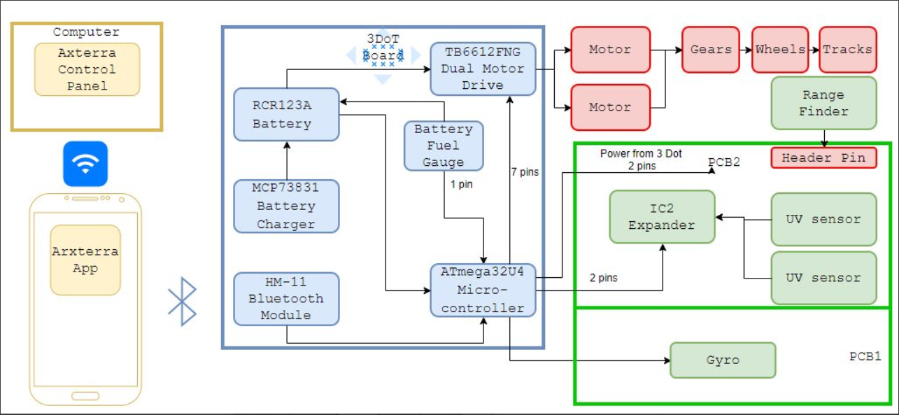
Figure 21 – Fritzing diagram of the system with the 3DoT
[av_textblock size=” font_color=” color=” av-medium-font-size=” av-small-font-size=” av-mini-font-size=” admin_preview_bg=”] The purpose of this PCB design is to design an IR Sensor Shield for four QRE1113 IR reflectance sensors to accomplish line following tasks. The original idea came from a product that was used in EE444 class – Sparkfun QRE1113 Digital Breakout Board. Due to the design requirements, the breakout boards are too big to fit in our robot scale, hence this new IR Sensor shield design.
Figure 22 – The breadboard fritzing diagram for IR sensors
This design contains four capacitor discharge circuits, which each contains one 100 ohm resistor, one 220 ohm resistor, one 10nF capacitor, and one QRE IR Sensor. The reason for these choices was made with the reference to Sparkfun QRE1113 Digital Breakout Board’s capacitor discharge circuit design. To keep the design efficient and fit the size requirement, no other components were added. This design measures the amount of reflection from a capacitor discharge circuit. When the power is supplied, the IR LED inside the sensor will illuminate, the phototransistor connected to the 10nF capacitor will receive reflection then cause the capacitor to discharge. Finally, the microcontroller receives discharge rate and output the numbers, the faster that capacitor discharges, the more reflective(lighter color) the surface is. The design was initially tested on a breadboard with a Sparkfun Pro Micro board, the Fritzing diagram is shown below.
Figure 23 – Eagle schematic of the IR sensor shield
Then, the PCB schematics are designed using EagleCAD. An additional 10uF capacitor that connected directly between VCC and GND is added to the design to reduce the impact of the current spikes during the switching, and also provides a low impedance path to ground to reduce noise from signals.
From the design of line following code and previous tests, the layout of IR sensors are determined as two pairs of IR sensors 15mm apart from each other and sensors in each pair are next to each other. In order to fit with overall robot design, the width of the PCB was determined to be 35mm, which is the same as the 3DoT board. The PCB is also designed to have 2 layers with polygon to have higher efficiency on the power supplying and noise reducing. All resistors and capacitors are chosen to be the size of 0603 and surface-mount. All IR sensors and headers are rated size and through-hole mounted, since they will be handled a lot, in order to provide better overall quality, through-hole design for these components is a more secure option and ensure to cause minimum damage when handling, as advised by the TA. The final PCB layout design is shown below.
Figure 24 – IR shield Eagle board layoutFigure 25 – Image of assembled and functional PCB
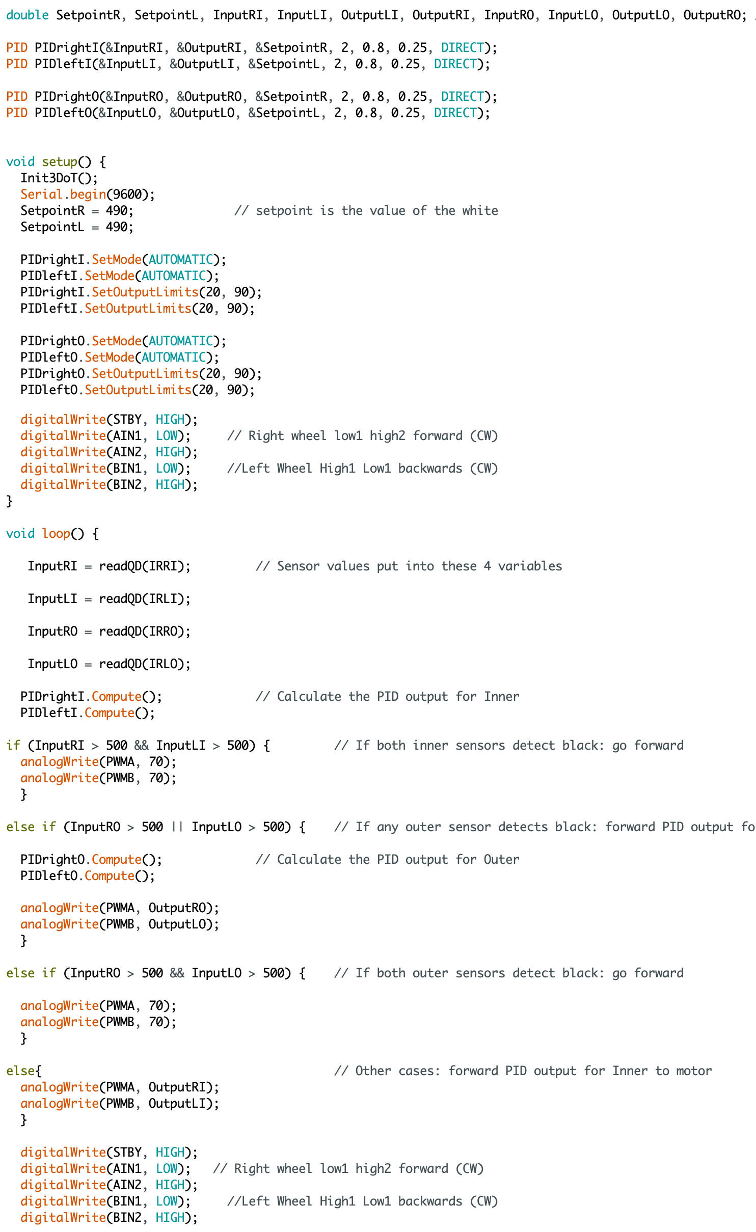
[av_textblock size=” font_color=” color=” av-medium-font-size=” av-small-font-size=” av-mini-font-size=” admin_preview_bg=”] Firmware implemented in this project is Line Following and PID Calculation. Line following and PID code were accomplished with an Arduino PID library. It allows the user to customize the PID coefficients and the set points in order to smoothly follow the line.
Figure 26 – Code for controlling the robot with PIDFigure 27 – A visual of the final code and how it is like a bit bang controller
[av_textblock size=” font_color=” color=” av-medium-font-size=” av-small-font-size=” av-mini-font-size=” admin_preview_bg=”] For the final design here is a list of the key features of the overall project:
Door Panel: Allows for quick access to the USB port and On/Off switch, as well as serve as an entrance for the 3 dot board to slide into and serves as a holder to keep the 3DoT in place.
Tension System: Allows the tank treads to stretch further; therefore, provide better movement overall of the tank to prevent snagging. To compensate for ride height issues caused by this tension system the magnet plate was redesigned to be adjusted vertically and ultimately move closer to the surface of the whiteboard.
Big Idler Wheels: Referencing back to previous semester’s design, they would use a metal axle to connect the two idler wheels through the two plastic side panels. However, this caused an issue in the friction produced as the tank experienced motion. This new design was fixed with the implementation of 3M ball bearings, thus establishing a foundation to mount each idler wheel individual of the other and spin freely without much friction as the idler spins on the inner race of the bearing.
Hollow Sprocket Drive Wheels: To accommodate for the narrow inner width of the tank that fits the 3DoT perfectly, The motors no longer fully fit inside the motor housing so the gearboxes stick out. The design from Sojourner’s wheel assembly was implemented into this design where essentially a “hollow” sprocket wheel encases the gearbox; therefore, allowing it to stick out of the motor housing.
Overall Scale: Although our tread width is slightly off, the overall dimensions of this design are much more accurate in scale to the real Goliath 302 Tank; ultimately, highlighting its narrow inner width and extruded length.
*Several iterations were performed as part of the engineering method and design process, before this final product. It can be seen here…
The Final Design
The following images showcase the fourth prototype, the closest looking version compared to the final (slight changes were made in the 5th (final) iteration):
Figure 28 – Prototype 4
Prototype 3 design (shown below to highlight key aesthetic and mechanical modifications improved on with Prototype 4)
Figure 29 – Prototype 3
Different angles of Prototype 4:
Figure 25 – Side view of proto 4Fig 30 – Frontal view of proto 4
It can be seen from the 1st picture below, from a side view of the tank, how the tension system works, with two 20 mm long bolts (including head) that are tightened to press against the inner sliding block that contains the 4 small tension arms.
Figure 31 – Inner side view of proto 4
The picture below illustrates one initial design of the bearing system, where now in the final print the bearings slide in from the inner wall of the side panel as mentioned before.
The pictures below illustrate the door panel opened and closed. The sleek design shows how thin or narrow the inner width of this tank is, which highlights a feature of the real Goliath tank.
Figure 32 – Door panel open viewFigure 33 – Door panel closed
Solid Works screenshots of Final Product (final print arriving the day before final):
Figure 34 – Final 3D model
The added top door hatch can be seen from the picture above.
Figure 35 – Back view of the final model
From the picture above, new door panel holders were designed to avoid the use of bolts.
Figure 36 – View of the magnetic plate
The picture above showing the magnet plate assembly.
Figure 37 – Front view of the final 3D modelFigure 38 – Side view of the final modelFigure 39 – Second side view of the final model
The following image of the robot has a top panel that is used to hold the phone as well as highlight a key feature in a certain version of the Goliath 302 tank, so the design is still following guidelines on depicting the actual Goliath tank. The final design also includes big idler wheels with teeth just in case the tracks slip off and we need something to keep them on.
Figure 40 – Final model with the added back hatchFigure 41 – Removable hatchFigure 42 – Big Idler Wheel with Teeth
Overall the robot seems to successfully demonstrate the movement and aesthetics of the Goliath tank; the wall climbing aspect has some issues, we will try and implement small magnets on the treads to further allow grip and better movement on the wall; however, if its not possible then this would be a perfect modification to be done in the future to enhance the mobility and grip of the tank on the whiteboard.
[/av_textblock]
[av_textblock size=” font_color=” color=” av-medium-font-size=” av-small-font-size=” av-mini-font-size=” admin_preview_bg=”]
In E-Racer’s test plan, there are three test cases label as TC-01 Operation Tests, TC-02 Visual Based Tests, and TC-03 Mission Execution Tests. All the test cases are performed in a classroom environment either on the ground or on the whiteboard. The purpose of TC-01 is to show that the E-Racer can function properly without the challenge of climbing the whiteboard. In TC-02, we verify if we meet requirements related to physical appearances and size by mostly inspection. The requirements verified in TC-03 are those related to the mission performed primarily on the whiteboard. The TC-01 will show us what can be done, but TC-03 see if it can do those tasks on a whiteboard.
For more details see the V&V Test Plan.
[/av_textblock]
Use something else besides nuts & bolts to assemble robot
Reduce the weight
Custom treads
Improving the three bullet points listed above will allow the robot to climb the whiteboard easier. The custom treads will reduce the size of the overall tank. Also the custom treads could be designed to implement tiny magnets in the tread to improve traction on the whiteboard.
Tips:
Label all extrusions in SolidWorks
Smart dimension could not only be used to specify the size of the part but also the position of the part. You can do this by clicking the edge of the part and the of something to specify how far you want to make the first part from the second part.
You can save all the parts in assembly as one part by click options and checking the “save as one part” box when saving your assembly as an STL file.
Save money at the library by putting all parts in one STL file (min per file $5)
Future managers don’t be afraid to assign tasks to your group. Check on them to make sure they are on track and on time. Make sure you see proof of what they say they are doing/did.
[av_textblock size=’30’ font_color=’custom’ color=” av-medium-font-size=” av-small-font-size=” av-mini-font-size=” admin_preview_bg=”] Line Following using a QRE1113 IR Sensor
[/av_textblock]
[av_textblock size=” font_color=” color=” av-medium-font-size=” av-small-font-size=” av-mini-font-size=” admin_preview_bg=”]
This blogpost is intended for keeping a record on IR Sensor Testing and Coding with Sparkfun QRE1113 Digital Breakout Board in the process of E-Racer Robot Project in EE-400D Class at CSULB.
Requirements need to be met are:
L1.28 All 3DoT robots shall incorporate the 3DoT v8 or v9 series of boards.
L1.29 Software shall be written in the Arduino De facto Standard scripting language and/or using the GCC C++ programming language, which is implements the ISO C++ standard (ISO/IEC 14882:1998) published in 1998, and the 2011 and 2014 revisions. Required exceptions to this standard can be found here.
L1.1 The E-Racer will drive on horizontal surfaces made of linoleum(classroom floor).
L1.3 The E-Racer shall be able to follow a course drawn on the 12’x5’ whiteboard in a classroom.
L1.7 The E-Racer shall begin moving forward anywhere within the defined start-finish area on the whiteboard.
L2.4.1 The PCB shall contain the IR sensors used for line following.
L2.6.1 The E-Racer shall implement PID control to autonomously follow the line.
[/av_textblock]
[av_heading tag=’h1′ padding=’10’ heading=’IR Sensor Testing’ color=” style=” custom_font=” size=” subheading_active=” subheading_size=’15’ custom_class=” admin_preview_bg=” av-desktop-hide=” av-medium-hide=” av-small-hide=” av-mini-hide=” av-medium-font-size-title=” av-small-font-size-title=” av-mini-font-size-title=” av-medium-font-size=” av-small-font-size=” av-mini-font-size=”]
Stuff we will put here woohoo…
[/av_heading]
[av_textblock size=” font_color=” color=” av-medium-font-size=” av-small-font-size=” av-mini-font-size=” admin_preview_bg=”]
The reasons for choosing QRE1113 are the following:
In EE444 class at CSULB, students used four(4) Sparkfun QRE1113 Digital Breakout Board for line following purpose and performed well. Since the project manager had experience with this sensor, and in order to follow Professor Gary Hill’s instruction “Don’t reinvent the wheels,” the project team decided to use Sparkfun QRE1113 Digital Breakout Board for initial testing and later applying QRE1113 sensor to the IR Sensor Shield Design.
Following paragraph is quoted from Sparkfun’s website, explaining how Sparkfun QRE1113 Digital Breakout Board works:
“This version of the QRE1113 breakout board features a digital output, using a capacitor discharge circuit to measure the amount of reflection. This tiny board is perfect for line sensing when only digital I/O is available and can be used in both 3.3V and 5V systems. The board’s QRE1113 IR Reflectance Sensor is comprised of two parts – an IR emitting LED and an IR sensitive phototransistor. When you apply power to the VCC and GND pins the IR LED inside the sensor will illuminate. A 100Ω resistor is on-board and placed in series with the LED to limit current. The output of the phototransistor is tied to a 10nF capacitor. The faster that capacitor discharges, the more reflective the surface is. These sensors are widely used in line following robots. White surfaces reflect more light than black, so, when directed towards a white surface, the capacitor will discharge faster than it would when pointed towards a black surface.” [1]
There is another version of the Sparkfun QRE1113 Breakout Board, which is the analog version. The difference between the Digital version and the Analog version is that digital version give output according to the time for the capacitor to discharge, and the analog version has a 10kΩ resistor that pulls the output pin high, as the light from the LED is reflected back onto the phototransistor, the output which is voltage measurement will begin to go lower.
[/av_textblock]
[av_textblock size=” font_color=” color=” av-medium-font-size=” av-small-font-size=” av-mini-font-size=” admin_preview_bg=”]
The first task once one has access to a sensor breakout board is to test if they work and learn how to read data from them.
The analog version uses very simple codes to get results:
Figure 1.1 Code for testing Sparkfun QRE1113 Analog Breakout Board [2]while the digital version uses more complicated codes:
Figure 1.2 Code for testing Sparkfun QRE1113 Digital Breakout Board[2]Since the breakout boards that the project team decided to use are digital versions, the following tasks are performed with the digital version. Shown below are the codes for initial testing:
Figure 2.1 Arduino Code for IR Sensor testing
In the initial testing, one breakout board was connected on Arduino, and as it was moving across a black line that was drawn on the whiteboard, the board outputted numbers like these:
Figure 2.2 Reading from IR Sensor Testing
The numbers in the window indicate how much reflection the sensor is detecting. The larger the number, the darker the surface is.
After several testing, a conclusion is derived that the threshold of detecting a black line is varied by factors like lighting condition, shadows, and surface material.
The threshold is very important and will be used later when designing codes for line following to determine whether sensors are detecting line and if the robot needs to make adjustments.
[/av_textblock]
[av_textblock size=” font_color=” color=” av-medium-font-size=” av-small-font-size=” av-mini-font-size=” admin_preview_bg=”]
After proving that the breakout boards work, the next step is to implement them into a robot to make it completes line-following tasks.
The robot used for IR sensor code testing is from EE444, it contains two motors, two encoders(not needed), four IR breakout boards, one microcontroller board, and one motor driver.
Note that, it is needed to pay attention to the choice of microcontroller board for testing before having access to a 3Dot board. Commonly used boards like Arduino Nano have ATmega328 microcontroller chip. However, when designing a robot that will eventually use a 3Dot board, a board with ATmega32U4 microcontroller chip is needed, for example, Sparkfun Pro Micro is a good choice, as it is small in size and it uses ATmega32U4 microcontroller chip. In this project, Sparkfun Pro Micro is used for code testing. The connection of all parts is shown in Figure 3:
Figure 3 Fritzing Diagram for Test Robot Connections
Code created for line following tasks:
Figure 4 Code for Test Robot Line Following with Updated Control Loop
These codes contain PID calculation, sensor reading, PWM writing for motors, and all the necessary setups.
The code “PIDright” and “PIDleft” are code needed to tune PID program to give better preference in following the line, these parameters have relations to how PID method works, which was explained in EE370, EE470, and EE471 class in CSULB. To find out the best parameters, we had to test their performances in reality. Theoretically, a higher P will give a faster and more precise reaction, and I term is to limit the speed of the steering response and reduce oscillation, and D term is to add more steering action in case of the error persists for too long.PID tuning is very important to make the robot work after determining the set point for white and black.
Figure 5.2 shows the flowchart explaining how the code works.
Figure 5 Flowchart for Line Following Control Loop
Here is a video of the robot doing line following using code designed above.
[av_textblock size=” font_color=” color=” av-medium-font-size=” av-small-font-size=” av-mini-font-size=” admin_preview_bg=”]
In this blogpost, QRE1113 Digital Breakout Board is used to test the performance of PID and line following code.
All requirements are met during the testing process, and the robot successfully performed line following task following an 8 figure on a whiteboard.
[/av_textblock]
[av_textblock size=” font_color=” color=” av-medium-font-size=” av-small-font-size=” av-mini-font-size=” admin_preview_bg=”] The E-racer’s functionality requires it to remain attached to a whiteboard. In order for the robot to overcome the force of gravity and keep from falling, an equal and opposite force must act on the robot. This force is the frictional force, which is created by the contact of the robot’s treads with the whiteboard in conjunction with a force that squeezes the two surfaces together. The ratio of the frictional force to this squeezing force is called the coefficient of friction. Knowing the coefficient of friction will allow the magnetic force to be defined as a function of the robot’s mass.
[/av_textblock]
[av_heading tag=’h1′ padding=’10’ heading=’Theory’ color=” style=” custom_font=” size=” subheading_active=” subheading_size=’15’ custom_class=” admin_preview_bg=” av-desktop-hide=” av-medium-hide=” av-small-hide=” av-mini-hide=” av-medium-font-size-title=” av-small-font-size-title=” av-mini-font-size-title=” av-medium-font-size=” av-small-font-size=” av-mini-font-size=”]
Stuff we will put here woohoo…
[/av_heading]
[av_textblock size=” font_color=” color=” av-medium-font-size=” av-small-font-size=” av-mini-font-size=” admin_preview_bg=”] The coefficient of static friction is the fraction of an object’s weight that must be applied to it laterally in order to get it to move. Every combination of two materials has a unique coefficient that must be ascertained experimentally. There are two types of friction: static friction and sliding friction, which is sometimes called kinetic friction. The coefficient of sliding friction is the fraction of an object’s weight that must be applied to it laterally in order to keep it moving after its static friction has been overcome and is usually less than the coefficient of static friction.
Sliding friction should not be applicable to the E-racer, because the surface of the treads should always be stationary with respect to the board as they move the robot. The term coefficient of friction as it appears in the rest of this text refers to the coefficient of static friction. Also, usually the force of friction is caused by gravity, and an outside force needs to be applied perpendicular to gravity in order to overcome the frictional force. In E-racer’s case, the frictional force is caused by the magnetic force, and the force that would oppose the force of friction would be gravity.
In order to use a more general term to avoid confusion, the term normal force is used to refer to the force that is applied orthogonal to the plane of the surfaces which are touching. In this case, the normal force points into the whiteboard. Additionally, the frictional force is the force that opposes the change in motion. Formally, the force of friction is defined as:
Figure 1 – Equation for the force of friction
Where F is the force of friction, ? is the coefficient of friction, and N is the normal force. So the more general definition of the coefficient of friction is the fraction of an object’s normal force that must be applied perpendicular to the normal force in order to get the object to move.
[/av_textblock]
[av_textblock size=” font_color=” color=” av-medium-font-size=” av-small-font-size=” av-mini-font-size=” admin_preview_bg=”] In order to determine a coefficient of friction, an experiment needed to be devised in order to find a relation between the frictional force and the normal force. The secret to devising such an experiment is to use geometry to translate the reading from an instrument into the coefficient. The experiment was conducted by placing a piece of tank tread on a small whiteboard, tilting the board until the tread slipped, and measuring the angle at which it slipped with a leveling application on a smartphone. This angle theta is defined to be the angle between the whiteboard and a level table as shown in Figure 2.
Figure 2 – Visual description of theta
After defining the experiment’s geometry, a free body diagram can be composed to define the forces exerted on the tread. The key to understanding how the free body diagram is useful is to realize that the angle that the board makes with the table is the same angle that the normal force makes with the gravitational force. Using trigonometry it can be shown that the magnitude of the normal force is mgCos(?) where m is the mass of the tread, g is the acceleration of gravity, and ? is the angle that the board makes with the table. Additionally, the frictional force is mgSin(?). These forces can be seen in the free body diagram of Figure 3.
Figure 3 – Free body diagram of the forces
The desired variable, ?, can then be defined in terms of the experiment’s variables. By definition:
Figure 4 – Derivation of the coefficient of friction from the free body diagram
[/av_textblock]
[av_heading tag=’h1′ padding=’10’ heading=’Results’ color=” style=” custom_font=” size=” subheading_active=” subheading_size=’15’ custom_class=” admin_preview_bg=” av-desktop-hide=” av-medium-hide=” av-small-hide=” av-mini-hide=” av-medium-font-size-title=” av-small-font-size-title=” av-mini-font-size-title=” av-medium-font-size=” av-small-font-size=” av-mini-font-size=”]
Stuff we will put here woohoo…
[/av_heading]
[av_textblock size=” font_color=” color=” av-medium-font-size=” av-small-font-size=” av-mini-font-size=” admin_preview_bg=”] So the coefficient of friction is simply the tangent of the angle between the board and the table. After the methodology of the experiment was established, the experiment was conducted many times to establish an average coefficient of friction. The results of the experiment can be seen below in Figure 5 and 6.
Figure 5 – The tabulated dataFigure 6 – The distribution of 21 tests
The distribution appears to be trimodal, meaning that three distinct averages seem to be appearing. From this realization, it was concluded that the orientation of the tread was significant. Before the test was conducted, it was assumed that the orientation was insignificant, but the results seemed to deny this assumption. Each orientation: sideways, tread pattern down, and tread pattern up appeared to have their own coefficient. After this new assumption was made, the test was repeated with the tread only its normal operational orientation, tread pattern down. The results of this test can be seen below in Figure 7 and 8. This time the test was conducted 26 times.
Figure 7 – The tabulated data for the second testFigure 8 – The second round of test with the tread pattern down
The same trimodal distribution occurred, but this time the outer means were less pronounced relative to the inside. The average value was a coefficient of static friction of 0.5449 with a standard deviation of 0.0522.
[/av_textblock]
[av_textblock size=” font_color=” color=” av-medium-font-size=” av-small-font-size=” av-mini-font-size=” admin_preview_bg=”] The results of this test confirmed that the frictional force of our robot needs to be about 54.49% of the normal force. In other words, the weight of our robot can’t exceed 54.49% of the attractive force of the magnets, or the robot will lose traction and fall off of the whiteboard. The maximum weight can be plotted as a function of the magnetic force using a simple linear function:
Figure 9 – The coefficient of friction equation applied to our robotFigure 10 – The maximum weight of the robot as a function of magnetic force
[av_textblock size=” font_color=” color=” av-medium-font-size=” av-small-font-size=” av-mini-font-size=” admin_preview_bg=”]
The Goliath Robot is based on the Goliath 302 Tank from World War II. We will be creating an indestructible, force of nature designed to track hills and rugged terrain. The Goliath, with its unique and interesting model, will be at the forefront of all robots. The purpose of this document is to provide a summary of the Goliath Fall 2018 Project. This document will provide useful links and resources of all the major tasks performed this semester as well as major tasks that were used from previous semesters.
[/av_textblock]
[av_heading tag=’h2′ padding=’10’ heading=’Program and Project Objectives’ color=” style=” custom_font=” size=” subheading_active=” subheading_size=’15’ custom_class=” admin_preview_bg=” av-desktop-hide=” av-medium-hide=” av-small-hide=” av-mini-hide=” av-medium-font-size-title=” av-small-font-size-title=” av-mini-font-size-title=” av-medium-font-size=” av-small-font-size=” av-mini-font-size=”]
Stuff we will put here woohoo…
[/av_heading]
[av_textblock size=” font_color=” color=” av-medium-font-size=” av-small-font-size=” av-mini-font-size=” admin_preview_bg=”] Program Objectives
The Robot Company (TRC) will be debuting its 2019 line-up of toy robots and associated games at the Toy-Invasion 2019 convention in Burbank CA on January 6, 2019. Your team’s assignment is to make the 3D printed and/or laser-cut prototypes to be showcased at the convention, prior to production starting in the second quarter of 2019. The robots will feature our new ArxRobot smart phone application and the Arxterra internet applications allowing children to interact and play games around the world. In addition, the robots should be able operate autonomously in game mode. See game(s) (i.e, mission objectives) assigned to your robot by the Game Division. To decrease electronics cost, interoperability between all TRC robots will be maintained by incorporation of the 3DoT board, developed by our Electronics R&D Section. Modification of downloadable content is limited to software switch setting and robot unique graphics of the smart phone and Arxterra applications. Modifications of electronics is limited to custom 3DoT shields as required by the unique project objectives of your robot. The Marketing Division has set our target demographic as children between the ages of 7 and 13, with a median (target) age of 11. To decrease production costs, please keep robots as small as possible, consistent with our other objectives. As with all our products, all safety, environmental, and other applicable standards shall be met. Remember, all children, including the disabled are our most important stakeholders. Our Manufacturing Division has also asked me to remind you that Manufacturability and Repairability best practices must be followed.
Project Objectives
The TRC Goliath project will offer an opportunity to study the limitations of a robot over a realistic terrain. A Goliath robot offers increased maneuverability and improved stability over traditional tanks. Its small size and light weight feature allows it to be well suited for young kids while also being sturdy. Its tracked-wheel system will allow the tank to traverse around rugged terrain. Its integration with an Android phone using the Arxterra App and open-sourced control boards allows for future builders to easily recreate or improve on the Goliath design.
[/av_textblock]
[av_textblock size=” font_color=” color=” av-medium-font-size=” av-small-font-size=” av-mini-font-size=” admin_preview_bg=”]
The goal of Fall 2018 Goliath is to improve on the Goliath 302 tank design from Fall 2016. The Mission is to navigate a 2-D paper/cloth maze under remote control through the Arxterra App and have the Goliath repeat the route autonomously.
[/av_textblock]
Fig. 1 This is the outside view of the Goliath F’18Fig. 2 Shown is the inside components of the Goliath F’18 containing the 3Dot Board, the gear system, and the motors
[av_textblock size=” font_color=” color=” av-medium-font-size=” av-small-font-size=” av-mini-font-size=” admin_preview_bg=”]
Based on the customer’s expectations and the mission objectives, we have come up with various Level 1 Requirements that are quantitative, verifiable, and realizable. This allows us to move the design process forward and obtain a clear understanding of what we are trying to accomplish.
[/av_textblock]
[av_textblock size=” font_color=” color=” av-medium-font-size=” av-small-font-size=” av-mini-font-size=” admin_preview_bg=”]
We are in compliance with constraints on the project imposed by The Robot Company (i.e., CSULB) and Project Stakeholders. Specifically, we include University and applicable environmental, health, and safety standards and those safety standards specifically associated with the product (e.g., Children’s Toys).
Applicable Engineering Standards
IEEE 29148-2018 – ISO/IEC/IEEE Approved Draft International Standard – Systems and Software Engineering — Life Cycle Processes –Requirements Engineering.
Federal Communications Commission (FCC) Relevant standards for a product implementing a 2.4GHz radio, FCC Intentional Radiators (Radio) Part 15C, and Unintentional Radiators FCC Part 15B for CPU, memories etc.
NXP Semiconductor, UM10204, I2C-bus specification and user manual.
ATmega16U4/ATmega32U4, 8-bit Microcontroller with 16/32K bytes of ISP Flash and USB Controller datasheet section datasheet, Section 18, USART.
ASTM F963-17, The Standard Consumer Safety Specification for Toy Safety, is a comprehensive standard addressing numerous hazards that have been identified with toys. In 2008, the Consumer Product Safety Improvement Act of 2008 (CPSIA) mandated that the voluntary toy safety standard in effect at that time become a nationwide mandatory children’s product safety rule.
Disposal of Hazardous Waste including Electronic and Solar Cells
CSULB Physical Planning & Facilities Management (PPFM) Environmental Compliance Electronic Waste Handling and Disposal Procedures. These procedures shall be followed for the disposal of all batteries.
[/av_textblock]
Subcategories: Cost, Extensibility, Interoperability, Maintainability, Quality, Marketability, and Schedule
All 3DoT robots shall be constrained to a not to be exceed Cost of $250.
All project Schedules shall be constrained to a completion date of Tuesday December 18, 2018. Project completion includes documentation and materials purchased by or loaned to the project.
One of the Economic Factors affecting our robots are return rates. To demonstrate the durability and child friendliness of our robot a simple drop test from 1.4 meter shall be performed. The height is defined by the average height of an average 11 year old girl.
Extensibility is designed into the 3DoT board by way of one 8-pin 100 mil connector located on the front of the board and two 8-pin 100 mil connectors located on the top of the board. By plugging shields into these connectors, the 3DoT board can support a diverse set of robots. All robots shall contain one or more custom designed 3DoT shields. The 3DoT shield(s) incorporating interface electronics between the 3DoT board and sensors and/or actuators unique to the robot. Surface Mount Technology (SMT) will be employed unless a waiver for through-hole parts is granted.
Maintainability: Disassemble and Reassemble of the robot shall be constrained to less than 20 minutes (10 + 10 minutes). Disassembly: The 3Dot board is clear of all other electronic and mechanical subassemblies. All electronic and mechanical subassemblies and associated connectors, sensors, and actuators including motors are disconnected. A functional test of the robot is conducted after reassembly to confirm its functionality. All project may reference a cable tree as well as an assembly diagram as necessary. This requirement is demonstrated/verified on the last day of the schedule. Projects may request a waiver with justification.
Social and Ethical
Subcategories: Accessibility, Aesthetics, and Usability
Accessibility by the blind and Marketability of the robots shall be implemented/enhanced by a speaker. The speaker shall generate sound effect consistent with the type of the robot. For example, the Goliath tank would make “track” sounds, the AT-ST sound effects would mimic their Star Wars antecedent.
To enhance Aesthetics, the robot shall be designed in such a way that there are no dangling or exposed wires. Connectors will used between all electronic and electromechanical components. Jumper wires will not be used, ribbon cables are preferred.
To enhance Aesthetics, the form factor of a robot modeled on a real or fictitious robot shall be constrained by the original. For example, Goliath should be a scale model of the real Goliath 302 tank. Projects may request a waiver with justification.
Usability of the robots shall be enhanced by adding autonomous functions and/or by use of the Arxterra phone application as dictated by the assigned mission.
Manufacturability
Subcategories: Constructability, Size, Weight, and Power (SWAP)
Constructability of 3DoT robots shall be documented at the CDR and approved by the president of the TRC robot company. Constraints imposed by this requirement include the use of bushing or bearings in all moving and rotating parts. Interlocking Hinges with latching mechanism. No gaps greater than 1 millimeter, and immediate access to all external connectors (USB, switches).
Manufacturability of 3D printed robots shall be demonstrated by compliance with the 3/3/3 rule. Specifically, total print of a robot is constrained to 9 hours, with no single print taking longer than 3 hours. Projects may request a waiver with justification.
The Size of the electronics enclosure, shall be constrained to be no greater than the 3DoT board, 3DoT shield(s), and associated mounting hardware.
Power to all 3D robots shall be provided by the 3.7V RCR123A battery included with the 3DoT board or use of the external battery 2.0mm PH series JST connector located on the 3DoT board. The RCR123A is a Lithium Polymer LiPo battery. All Safety regulations as defined in Section 4.3 Hazards and Failure Analysis of this document shall apply to the shipping, handling, storage, and disposal of LiPo batteries.
Back of the envelope calculations and experiments shall be conducted to set the diameter of Power carrying wires. Follow the American Wire Gauge (AWG) standard when defining the diameter of power carrying wires. This work to be completed and documented by the CDR.
Environmental Health and Safety (EH&S) Standards
Subcategories: Environmental Standards, Sustainability, Toxic waste (Solar panels), Health and Safety, Ergonomics
All standards, codes, and regulations as defined in the “Engineering Standards and Constraints” Section of this document shall apply.
Functional
All 3DoT robots shall incorporate the 3DoT v7 series of boards.
Software shall be written in the Arduino De facto Standard scripting language and/or using the GCC C++ programming language, which is implements the ISO C++ standard (ISO/IEC 14882:1998) published in 1998, and the 2011 and 2014 revisions. Required exceptions to this standard can be found here.
All 3DoT robots shall be controlled via Bluetooth 4.0 in compliance with the Bluetooth Special Interest Group (SIG) Standard (supersedes IEEE 802.15.1).
[/av_textblock]
[av_textblock size=” font_color=” color=” av-medium-font-size=” av-small-font-size=” av-mini-font-size=” admin_preview_bg=”]
The Level 1 Functional Requirements describe the functions and characteristics that Goliath will have.
L1-1 Schedule – Project shall be completed by Tuesday, December 18th, 2018
L1-2 Operational Task – Goliath shall be responsive to user input commands from and send data to the ArxRobot mobile App
L1-3 Maintainability: Disassemble and Reassemble the robot shall be less than 20 minutes (10 + 10 minutes).
L1-4 Driving Surface – Should autonomously traverse shortest path of maze
L1-5 Driving Surface – The Goliath shall traverse on cloth, paper and linoleum
L1-6 Print Time – Total print time is less than 9 hours, with no single print taking longer than 3 hours
L1-7 3Dot – The Goliath should use the 3Dot Board
L1-8 Appearance – The Goliath shall appear in scale to the real Goliath 302 tank
L1-9 Functional – Goliath should be responsive to user input commands and sends telemetry to Arxterra
L1-10 Budget – The total cost of the Goliath shall remain under $250
L1-11 Funcitonal – The Goliath shall traverse a maze under remote control
L1-12 Functional – The Goliath should remember the manual instructions given for navigating the maze
L1-13 Aesthetics – Should have access to USB Port without tools
L1-14 Functional – The Goliath shall remain operating for at least 0.5 hours
L1-15 Aesthetics – The Goliath shall be smaller by volume than the previous version
L1-16 Economic Factors – Goliath should withstand impact of wall and other robots
L1-17 Power: Power to all 3Dot robots should be provided by the 3.7 volts RCR123A battery included with the 3Dot board
L1-18 Functional: The Goliath should be controlled via bluetooth
[/av_textblock]
[av_textblock size=” font_color=” color=” av-medium-font-size=” av-small-font-size=” av-mini-font-size=” admin_preview_bg=”]
The Level 2 Requirements are derived from the Level 1 Requirements. Based on a specific requirement, we came up with a Level 2 Requirement to meet the original requirement.
L2-1 Mechanical/Manufacturing –Based on L1-15, the mass of the Goliath shall not exceed 350 grams
L2-2 Electronics – Based on L1-17, the voltage drawn from the 3DOT should not exceed 3.6V
L2-3 Mechanical/Manufacturing – Based on L1-16, the Goliath should withstand impact of wall and other robots
L2-4 Electronics– Based on L1-17, the total current drawn from the 3DOT should not exceed 650mA
L2-5 Safety and Quality Assurance – Based on L1-3, the wires in Goliath shall be clean with no bare wire showing and wires tied together
L2-6 Mechanical/Manufacturing – Based on L1-15, the Goliath will be smaller than 4.71x 3.77 x1.8 inches (Fall 2016 size)
L2-7 Safety and Quality Assurance– Based on L1-16, the Goliath should withstand a drop test from 1.4 meters.
L2-8 Mechanical/Manufacturing – Based on L1-8, The Goliath should not exceed 20% of the original scaling factor
[/av_textblock]
[av_textblock size=” font_color=” color=” av-medium-font-size=” av-small-font-size=” av-mini-font-size=” admin_preview_bg=”] Allocated requirements, also known as resource reports, are written and tracked by the System Engineer. Each resource has a margin attached to it based on the uncertainty in the estimate. We also show contingency, where contingency is defined as the project allocation minus the estimate plus total margin.
[/av_textblock]
[av_textblock size=” font_color=” color=” av-medium-font-size=” av-small-font-size=” av-mini-font-size=” admin_preview_bg=”]
In this section we will discuss our work breakdown structure and our product breakdown structure. We will mention our schedule for the semester as well as the products that we ended up purchasing and their costs to use for the Goliath F’18.
[/av_textblock]
[av_textblock size=” font_color=” color=” av-medium-font-size=” av-small-font-size=” av-mini-font-size=” admin_preview_bg=”]
Project Work Breakdown Structure (WBS) and Product Breakdown Structure (PBS).
References:
Chapter 4, section 3 of the NASA Systems Engineering Handbook titled “Logical Decomposition” includes a section that briefly covers the Product Breakdown Structure (PBS.) Chapter 6, section 1 titled “Technical Planning” includes a section that explains the relationship between the Work Breakdown Structure (WBS) and the PBS. The PBS is the responsibility of the systems engineer. There is not quite enough information between these two sections to create a long presentation; instead focus on first going over the info, and then work with your division members to create an example PBS during the meeting.
[av_textblock size=” font_color=” color=” av-medium-font-size=” av-small-font-size=” av-mini-font-size=” admin_preview_bg=”]
For the Goliath 3Dot Robot this fall 2018 semester the team researched the necessary parts that we would be using to build the Goliath 302 tank. Below in the figure we can see the parts that we initially anticipated for this semesters project.
Figure #6 – Pre-Order form for Goliath Fall 2018
Towards the end of the semester, the team reached the conclusion that not all goals would be reached, and therefore reduced the Total cost of the Goliath Robot.
[av_textblock size=” font_color=” color=” av-medium-font-size=” av-small-font-size=” av-mini-font-size=” admin_preview_bg=”]
On our schedule, we were able to complete our motor testing to determine which motors we would be using as well as modifying the SolidWorks for the new gear system and new motor placement. At the time that the project was due, we had just finished up the 3D models on SolidWorks and had it printed. Unfortunately, the set up of the gear system was not what the customer wanted but we were out of time. We would say that we got around 70% of the work done, and it was the final implementation and design that we were not able to complete.
[/av_textblock]
[av_textblock size=” font_color=” color=” av-medium-font-size=” av-small-font-size=” av-mini-font-size=” admin_preview_bg=”]
For the Goliath 302 tank of Fall 2018, the team decided to go with the design from Generation #2 for an initial starting point. From here, the team created new mission objectives for our robot, and from there decided on what new design features we needed to implement.
[/av_textblock]
[av_textblock size=” font_color=” color=” av-medium-font-size=” av-small-font-size=” av-mini-font-size=” admin_preview_bg=”]
The first step toward reaching our objectives was to start from previous Goliath projects. We researched the previous generations through the Arxterra website to find a design that would be a good starting point. Once the team had the design, we needed to see how it needed to modify it in order to meet the level 1 and level 2 requirements. Using Solidworks, the team was able to achieve some of the new design changes like reducing the size of the Goliath, moving the motors to a new location, as well as a new bevel gear system. For the electronics part of the project, the team conducted multiple experiments ranging from calculating the amount of current drawn from the motors to finding out the different specifications of each motor. For the Firmware of the robot, the team used the Arduino Uno board to run code to make prototypes of the Goliath to move. Example of code could be found on the Arxterra website from previous generations. Overall, these were the different approaches the team made in order to reach our final mission statement.
[/av_textblock]
[av_textblock size=” font_color=” color=” av-medium-font-size=” av-small-font-size=” av-mini-font-size=” admin_preview_bg=”]
For this semester’s Goliath redesign, our main points of focus was to make the Goliath smaller, move the motors to the compartments in the side panels resulting in a new gear system being added, create a better latching system for the top and bottom panel, figure out a better way to attach the small rotating wheels, and add ribbing to increase the structural strength of the Goliath top and bottom panels. Shown below is the new bevel gear system we added to facilitate moving the motors to the side panels. To see more of the redesign and the changes we made, refer to the Goliath Fall 2018- Redesign blog post.
[av_textblock size=” font_color=” color=” av-medium-font-size=” av-small-font-size=” av-mini-font-size=” admin_preview_bg=”]
Our main project specifications was to move the motors of the Goliath into the already open space in the side panels. The proposed solution for moving the motors and not having them connect directly to the drive wheel anymore was a new gear system that was introduced above. This will allow the motor to sit in the side panels and allow us to remove excess space from the body which will then result in the Goliath fitting the 3Dot board tightly. This will result in a smaller volume of a Goliath that maximizes the space. The other components of the Goliath stayed relatively similar to past generations and not much was changed. The Goliath’s mission of navigating a maze through remote control through the Arxterra app and then navigating the path autonomously was the same as previous semesters. Our preliminary budget for the Goliath was around $350 including the sensors, 3D printing, and motors. We would like to have the Goliath completed by Tuesday, December 18, 2018.
[/av_textblock]
[av_textblock size=” font_color=” color=” av-medium-font-size=” av-small-font-size=” av-mini-font-size=” admin_preview_bg=”]
For this semester’s Goliath redesign, our main points of focus was to make the Goliath smaller, move the motors to the compartments in the side panels resulting in a new gear system being added, create a better latching system for the top and bottom panel, figure out a better way to attach the small rotating wheels, and add ribbing to increase the structural strength of the Goliath top and bottom panels.
Manufacturing Final Design
Our conceptual design included the motor being moved to the side panels. In the final design, we were not able to create a pocket for the motor and had to makeshift a pocket with foam. The motor successfully connected to the gear system and ran, but due to some manufacturing issues, we had to connect both sides of the gear system with a single shaft which was not what the customer wanted. The final design also was not as small as the customer had expected it to be. It was only modified in its width and not the length which is what the customer had anticipated being modified.
Electronics Final Design
With the team being limited to two people, the electronics portion of the Goliath did not meet the expectations that the team had originally thought. A prototype of the Goliath was 3D printed and could move to some extent via bluetooth commands. Unfortunately, the App that was used was not to Professors Hill’s liking, which he later expressed his feelings about it to the electronics team (although when presented to the ABET people, they actually liked it). Furthermore, the team also wanted to create a PCB design to make a clean wiring for sensors like the IR/Magnetometers sensors and the Gyro sensors. This plan was not met over this semester’s Goliath Project.
[/av_textblock]
This is the previous semester S’18 block diagram. We were ideally attempting to implement the same system and product. The system block diagram illustrates how components of the Goliath communicate and connect with each other; from the control panel that uses Wi-Fi to talk with the mobile app to the wheels and treads. More detailed specific components such as the HM11 Bluetooth model is added, and various parts on the PCB parts are laid out.
[/av_textblock]
[av_textblock size=” font_color=” color=” av-medium-font-size=” av-small-font-size=” av-mini-font-size=” admin_preview_bg=”]
For this Generation of the Goliath, DC motor Experiments were done to motors already obtained from previous Generations. The experiments helped conclude which DC motors would be ideal for our Goliath Robot to reach our mission objectives. Here is a link to those Experimental Results.
[/av_textblock]
This section provides a systems level look at the software modules employed by 3DoT robots. This section represents a collaborative effort by the system and electronics/control engineers.
[av_textblock size=” font_color=” color=” av-medium-font-size=” av-small-font-size=” av-mini-font-size=” admin_preview_bg=”]
Going into the project, there are some programs that one need to be familiar with in order to do well with the project. The Arduino scripting language is one of the programs that is used to control the tank; while Eagle CAD is another program that is used to design a custom PCB.
For the electronic components, one of the main components in this robot was the DC motors that are going to be used to move the Goliath. The experiments done during the semester was to determine how much current would be drawn from the each motor and whether or not that would be enough to move the Goliath or if it would be too much current that it might fry the board. Another electrical aspect of this project was the sensors that were meant to be used. A embedded systems class had worked on code for the IR sensors that could have been adapted to our Goliath tank.
[/av_textblock]
[av_textblock size=” font_color=” color=” av-medium-font-size=” av-small-font-size=” av-mini-font-size=” admin_preview_bg=”]
This is section shows the progression of the design from Fritzing diagram (optional), to physical breadboard photo, to PCB schematic, PCB layout, and finally a photo of the completed board; preferable integrated with the product itself.
The PCB design of this semesters Goliath was not created. The initial objective was to incorporate a mode on the Goliath to navigate the 2D maze using a magnetometer or IR sensor to follow the path.
[/av_textblock]
[av_textblock size=” font_color=” color=” av-medium-font-size=” av-small-font-size=” av-mini-font-size=” admin_preview_bg=”]
In order to complete the main goal of this mission, app directed control to the Goliath was needed. This comprehensive guide talks about how setting up custom commands all the way down to how the major whichway decision making within the maze is effected. This guide defines the general case used by all bots, but the code represented is the Goliath version.
Here is a link a previous Generations Code that was used this semester in order to use the App to send commands to the robot.
[/av_textblock]
The google drive file linked above contains all the SolidWorks files for the F’18 Goliath, including the new gear system given by Jeff Gomes. The design was based on the Gen 2 Goliath models and were modified accordingly. The main components to notice are the new gear system and how it sits in the body.
New Bevel Gear SystemFig. 12 How the Gear System fits in the GoliathFig. 13 How the Gear Fits in to the Opening
The Verification and Validation Test Plan verifies that our design meets design requirements and how we will validate that we built the right product for the mission.
[av_textblock size=” font_color=” color=” av-medium-font-size=” av-small-font-size=” av-mini-font-size=” admin_preview_bg=”] RESEARCH, RESEARCH, RESEARCH. At the start research as much as you can about the past project your building on (start at this document). Then read through all the posts from that semester. Lots of work has already been done and just uncovering it and reading may take time but, it is worth it.
Provide your group with some goal every week. This will help keep your project on task and helps the members remain focused on their independent tasks. Planing this isn’t easy but, as project manager just form a general goal and then ask everyone how to get there.
Get a Prototype working ASAP. The main reason is to have time for programming model iterations and so on. Without this, there is no code to write and the code will take the longest!
Start Coding EARLY. The programming work can be long and tiresome. Most programming takes hours troubleshooting per feature. Starting early gives the highest chance of success.
PCB Design has a long Verification time. Designing a PCB is the easy part, getting it approved, then assembled and working is the hard part.
Plan to iterate the 3D model at least 5 times. Get a 3D model designed (even if it is rough) and just get it printed. Each time you print it, there will be something to improve or fix that was not thought of. Plus by the time you get to the end the timeline, 3D printing and assembly will be easier. If you don’t know Solidworks find someone who does.
[/av_textblock]
[av_textblock size=” font_color=” color=” av-medium-font-size=” av-small-font-size=” av-mini-font-size=” admin_preview_bg=”]
These are the starting resource files for the next generation of robots. All documentation shall be uploaded, linked to, and archived in to the Arxterra Google Drive. The “Resource” section includes links to the following material.
[av_textblock size=” font_color=” color=” av-medium-font-size=” av-small-font-size=” av-mini-font-size=” admin_preview_bg=”]
In this Blog post we will analyze and determine the specifications of the motors that we currently have for the Goliath Tank. The Goliath Tank will require two motors that have both sufficient amount of torque and speed to efficiently move the Goliath through the maze. In order to improve on the previous Goliath’s design, we will be looking at the different motors the previous generations used. Through the RPMs and current experiments, as well as the Pololu website’s table of motors, we will be able to determine which motors will work for our Goliath.We had 5 motors from the previous generations and we needed to conduct experiments in order to figure out what the specifications are of each motor.
[/av_textblock]
[av_heading tag=’h1′ padding=’10’ heading=’Experiment #1′ color=’custom-color-heading’ style=” custom_font=’#f77300′ size=” subheading_active=” subheading_size=’15’ custom_class=” admin_preview_bg=” av-desktop-hide=” av-medium-hide=” av-small-hide=” av-mini-hide=” av-medium-font-size-title=” av-small-font-size-title=” av-mini-font-size-title=” av-medium-font-size=” av-small-font-size=” av-mini-font-size=”]
Stuff we will put here woohoo…
[/av_heading]
[av_textblock size=” font_color=” color=” av-medium-font-size=” av-small-font-size=” av-mini-font-size=” admin_preview_bg=”] The first experiment we did was to calculate the RPM’s of each Motor. First we attached a wheel to the motor, then added a white piece of paper with a black dot on one side in order to keep track of the rotations. In the figure below we can see the circular piece of paper and the motor that it was attached too.
Figure #1 – Materials used to estimate RPMs
Next we used a strobe light at different frequencies to try and estimate the RPM’s of each motor. As the motor rotated, the piece of paper turned and we kept track of the black dot each time the strobe light flashed. When the black dot’s position was the same each time the light would flash, then it was the correct frequency. The frequency of the strobe light was in units of Flashes per minute. Each time the light flashed and the dot was approximately in the same location, then that would correspond to one rotation of the motor. The same experiment was done for the rest of the motors.
[/av_textblock]
[av_textblock size=” font_color=” color=” av-medium-font-size=” av-small-font-size=” av-mini-font-size=” admin_preview_bg=”] The second experiment was to help determine the no load current, and stall current of each motor. First, we connected a multimeter to a 6v power supply (which was the amount of voltage that is used for the motor descriptions on the Polulu website) in series with the Polulu Motor in order to calculate the amount of current the motor would draw. The first results were for the no load current, where the motor would rotate freely and is the the least amount of current that it is going to draw. Dislcaimer: The following method to test the stall current is not ideal. Other ways to test the stall current can be more accurate while also minimizing effects on the motor.Next, we would hold on to the motor, prevent it from rotating, to calculate the stall current it is going to draw. We then performed these two steps again at a voltage of 3.3v which is around the voltage that the Goliath will be operating at when using the 3Dot board.
As mentioned above, a more adequate way to measure the stall current would be to add more and more weights to the load of the motor until it can not move the mass anymore.
[/av_textblock]
[av_textblock size=” font_color=” color=” av-medium-font-size=” av-small-font-size=” av-mini-font-size=” admin_preview_bg=”]
The results of the team’s experiment were as follows:
Motor #1 – This motor pulled about approximately 0.04 Amps at 6 and 3.3 Volts. The Stall current that was found was approximately 0.70 Amps at 6 Volts and 0.22 Amps at 3.3 Volts.The RPMs of the motor was calculated to be around 205 RPMs. When looked on the Polulu website for reference, the motor that closest matched our results was the Medium power motor with a 100:1 Gear Ratio and Stall torque of 0.94 Kg x cm
Motor #2 – This motor pulled about approximately 0.11 Amps at 6 Volts and 0.10 Amps at 3.3 Volts. The Stall current that was found was approximately 1.0 Amps at 6 Volts and 0.29 Amps at 3.3 Volts. The RPMs of the motor was estimated to be around 142 RPMs. The motor that matched these specifications on the Polulu website was the High Power Carbon Brush motor with a 210:1 Gear Ratio and Stall torque of 2.8 Kg x cm
Motor #3 – The third motor pulled about approximately 0.110 Amps at 6 and 0.097 Amps at 3.3 Volts. The Stall current that was found was approximately 1.01 Amps at 6 Volts and 0.668 Amps at 3.3 Volts. The RPMs of the motor was estimated to be 125.5 RPMs which approximately matched the Medium Power Motor with a 250:1 Gear Ratio and Stall torque of 3.2 Kg x cm
Motor #4 – The last motor pulled about approximately 0.0142 Amps at 6 and 0.0108 Amps at 3.3 Volts. The Stall current that was found was approximately 0.082 Amps at 6 Volts and 0.094 Amps at 3.3 Volts. The RPMs of the motor was estimated to be 35 RPMs which approximately matched the High Power Carbon Brush motor with a 1000:1 Gear Ratio and Stall torque of 11 Kg x cm
Figure #2 -Results of each Motor at 6Vs and 3.3Vs
After analyzing these results, the team concluded that motor #4 generates a high amount of torque while only supplying a small amount of RPMs. Although his will cause our Goliath to move a high amount of weight, the movement of the robot will be at a very slow velocity. Two other motors (motors #3 and #2) generate a good amount of torque, a range of 2.8-3.5 Kg x cm, but draw a large amount of current which might be a problem with the Goliath’s battery supply. If the Goliath gets stuck or requires more torque from the motors, then the current drawn might even burn out the board. The last motor (motor #1) was the motor which drew the least amount of current while still generating a torque of about 0.94 Kg x cm. Motor #1 is the motor we will be using for future tests on the Goliath.
[/av_textblock]
[av_textblock size=” font_color=” color=” av-medium-font-size=” av-small-font-size=” av-mini-font-size=” admin_preview_bg=”]
The overall motor testing was a success, and with the final results of our experiment we were able to find a motor to meet the needs of our Goliath while still maintaining a safe operation point. The team was able to find the motor with enough torque to move the Goliath while not drawing too much current that might drain the battery or fry the board.
[/av_textblock]
[av_textblock size=” font_color=” color=” av-medium-font-size=” av-small-font-size=” av-mini-font-size=” admin_preview_bg=”]
For the Fall 2018 Semester, the Goliath project was a redesign of the Goliath from Generation #2. We took the basic structural design of the robot and incorporated a new motor/gear system, as well as other modifications. The design of the Goliath of Generation #2 had small deficiencies that need to be corrected before it can run and function efficiently. In this blog post we will outline the deficiencies that Goliath #2 had as well as our new additional design incorporation.
[/av_textblock]
[av_textblock size=” font_color=” color=” av-medium-font-size=” av-small-font-size=” av-mini-font-size=” admin_preview_bg=”] The Generation #2 Goliath has small idle wheels that help align the tracks, but they cause a lot of friction which requires more torque from the motors. The extra work that the motors output results in more current being drawn which drains the battery life quickly. The current design for the idle wheels in the Goliath is shown in the figure below.
Figure 1: The SOLIDWORKS design for the idle wheels.
When the model is actually 3D printed, connecting the wheels to the side panels is not that easy and the wire that is used to connect the wheels hangs out and hits the tracks as seen below.
Figure 2: Idle wheels when printed and attached
In addition, the tracks are too close to the side panels which adds more friction each time the tracks and the side panels touch. When turning, the constant interaction between the panels and the tracks cause the tracks to be lifted out of place of the driving sprocket and then fall out of place which brings the Goliath to a stop.
In addition to the friction, the small idle wheels do not have a proper way to connect them to the Goliath. The current method of attaching them to the Goliath is by cutting small pieces of wires and hooking the wheels with the robot. As seen in the figure below, the current method is not effective because the excess wire that is left over hits the tracks each time the wheels turn which causes more friction for the motors to overcome.
[/av_textblock]
[av_textblock size=” font_color=” color=” av-medium-font-size=” av-small-font-size=” av-mini-font-size=” admin_preview_bg=”] The current latching system that the Goliath has for the top and bottom panel to connect does not work correctly. The panels have small, circular, hollow shafts at one end that would hold the panels together when a piece of wire or small nail is inserted. This design was not modeled correctly because the shafts do not fit correctly and would have to be forcefully connected. Currently, the top and bottom panels just lay on top of one another and are not connected. In the figure below we see the current latching system the the Goliath design has.
Figure 3: The latching system of Goliath Gen #2
When the Goliath gets printed and built, the actual latching does not physically level-up, or match up, and therefore they can not be connected correctly. In the next figure, we can see how the latches shafts are uneven and therefore a wire or nail cannot fit through them without force which may cause it to break.
[av_textblock size=” font_color=” color=” av-medium-font-size=” av-small-font-size=” av-mini-font-size=” admin_preview_bg=”] Finding a location to 3D print the goliath was another challenge that the team had to overcome when prototyping. Some small pieces of the robot had details that were not printed correctly and required to be printed again. One example of this is the driving sprockets of the robot. The triangular teeth at the end of wheel (the ones that grip the track in order for them to move) didn’t print correctly in one of the printing locations [5] we first went to. Although the 3D printing is not a direct defect of the design, improvements in the design can facilitate the 3D printing. In the figures below we can see the SOLIDWORKS model of the driving sprocket, and in the one below it of the actual 3D print.
Figure 5: Solidworks model of the driving sprocket.Figure 6: Actual 3D printed driving sprocket.
[av_textblock size=” font_color=” color=” av-medium-font-size=” av-small-font-size=” av-mini-font-size=” admin_preview_bg=”]
The Goliath will include the 3Dot board to control the motors as well as the code for the mission fo the Goliath. Based on the fact that we wanted to modify the Goliath to fit the 3.5 x 7 cm 3Dot board snugly and overall make the Goliath as small as possible, our initial dimensions are 11.37 x 7.78 x 4.58 cm.
Goliath 302 Tank Dimensions: 1.5 x 0.85 x 0.56 m
Determining Goliath Ratio with reference ratio 1.5 m:
L = 1.5/1.5 = 1
W = 0.85/1.5 = 0.567
H = 0.56/1.5 = 0.37
Ratio: 1 x 0.567 x 0.37
Our ideal F’18 Goliath dimensions based on the ratio would be 11.37 x 6.45 x 4.21 cm based on the calculations below:
L_ideal = 11.37 cm
W_ideal = L_ideal * Width Ratio = 11.37 * 0.567 = 6.45 cm
H_ideal = L_ideal * Height Ratio = 11.37 * 0.37 = 4.21 cm
Comparing our ideal and actual dimensions, we can find the percent error for the length, width, and height:
Our final dimensions are slightly larger than the ideal dimensions because we are leaving room for the motors in the side panels as well as the new gear system which we will discuss in this post.
[/av_textblock]
[av_heading tag=’h2′ padding=’10’ heading=’Gear System’ color=” style=” custom_font=” size=” subheading_active=” subheading_size=’15’ custom_class=” admin_preview_bg=” av-desktop-hide=” av-medium-hide=” av-small-hide=” av-mini-hide=” av-medium-font-size-title=” av-small-font-size-title=” av-mini-font-size-title=” av-medium-font-size=” av-small-font-size=” av-mini-font-size=”]
Stuff we will put here woohoo…
[/av_heading]
[av_textblock size=” font_color=” color=” av-medium-font-size=” av-small-font-size=” av-mini-font-size=” admin_preview_bg=”]
To eliminate unnecessary space, we moved the motors to the open compartment in the side panels of the Goliath. By doing so, we were not able to connect the driving wheel directly to the shaft of the motor as it has been in previous Goliaths. To compensate for this issue we added a new bevel gear system that was designed by Jeff Gomes. The motor will sit in the side compartment and its shaft will connect to a gear. That gear will drive another gear that is on the same shaft as the driving wheel, causing the wheel to move. The photos of the gear system and how it will fit into the Goliath are shown below.
Figure 7: New Bevel Gear SystemFigure 8: How the Gear System Fits in the Goliath
[av_textblock size=” font_color=” color=” av-medium-font-size=” av-small-font-size=” av-mini-font-size=” admin_preview_bg=”]
For the bottom and top panel, the length remained the same but by moving the motors, we were able to make the width of the two panels from 53.98 mm to 43.27 mm. The motor compartments were removed from the bottom panel to make room for the gear system as well. We also added a ribbing, which is the X on the panels, to help with the structural strength of the panels. Shown below is the bottom panel with the ribbing feature and also how the 3Dot will fit on the bottom panel more snugly. We are also working on a better latching system to connect the top and bottom panel together and also to be more secure.
Figure 9: Ribbing Feature on Bottom PanelFigure 10: 3Dot Board on Bottom Panel
[av_textblock size=” font_color=” color=” av-medium-font-size=” av-small-font-size=” av-mini-font-size=” admin_preview_bg=”]
For the side panels, we closed the side doors that in the previous generation would open up as a sensor, as we will not be needing it anymore because the mission of Goliath has changed. There was also the design flaw mentioned that involved the tracks being slightly too close to the side panels, creating more friction because it would rub against the panel. To fix that, we moved the wheel holders slightly out, roughly 1 mm. We also had to create an opening in the side panel to make room for the gears and the motor to connect to the driving wheel. Because the length of the side panel stayed the same, we did not have to worry about making sure the tracks would fit, allowing us to use the same set of tracks as the past generation. We also are working on a better way to attach the bottom and top wheels on the side panels. Shown below is the opening made and how the gear fits, and also the closed side doors.
Figure 11: Opening Made to Accommodate New Gear SystemFigure 12: How the Gear Fits in to the Opening
[av_textblock size=” font_color=” color=” av-medium-font-size=” av-small-font-size=” av-mini-font-size=” admin_preview_bg=”]
Overall, the design modifications that we made to the Goliath included moving the motors to the side compartments, resulting in a gear system added. We had to make room for the gears by making an opening in the side panel. We also shortened the width of the bottom and top panel to fit the 3Dot board better and also added ribbing to strengthen the structure. We are still working on a better latching system and a better way to attach the small wheels on the side panels.
[/av_textblock]

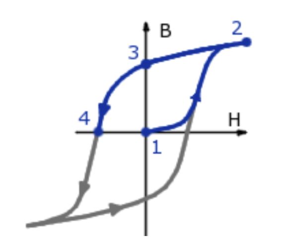
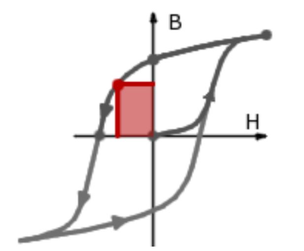
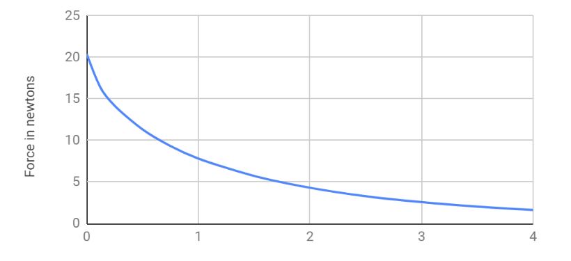
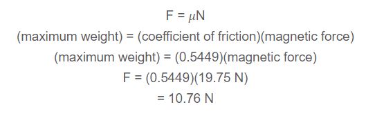
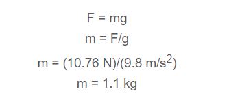
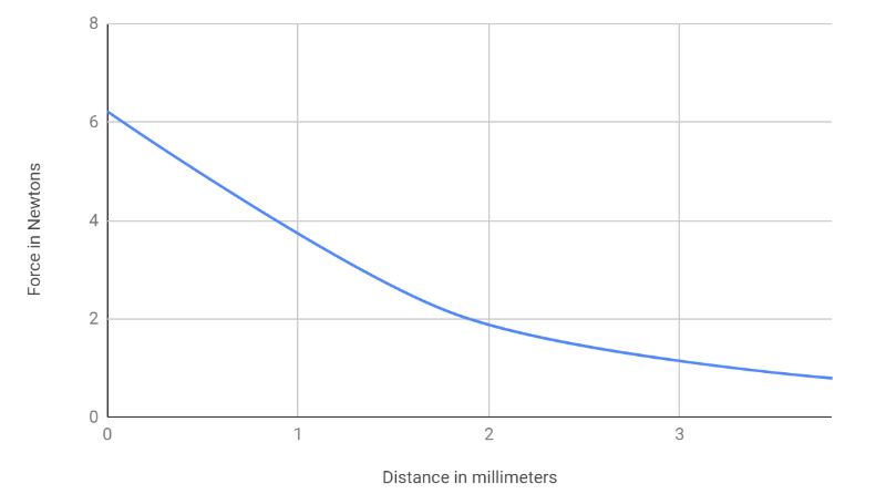
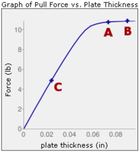
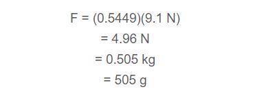
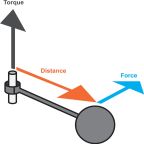
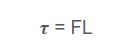
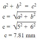
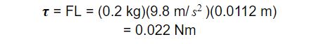
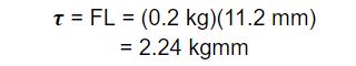
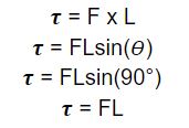
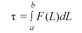
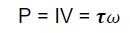
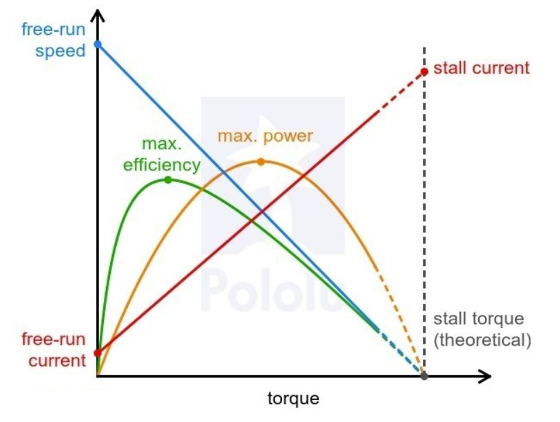
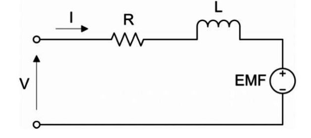
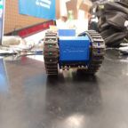
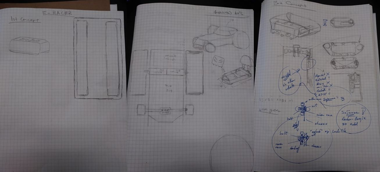
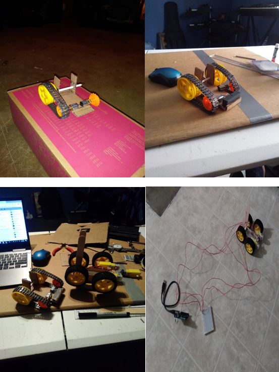

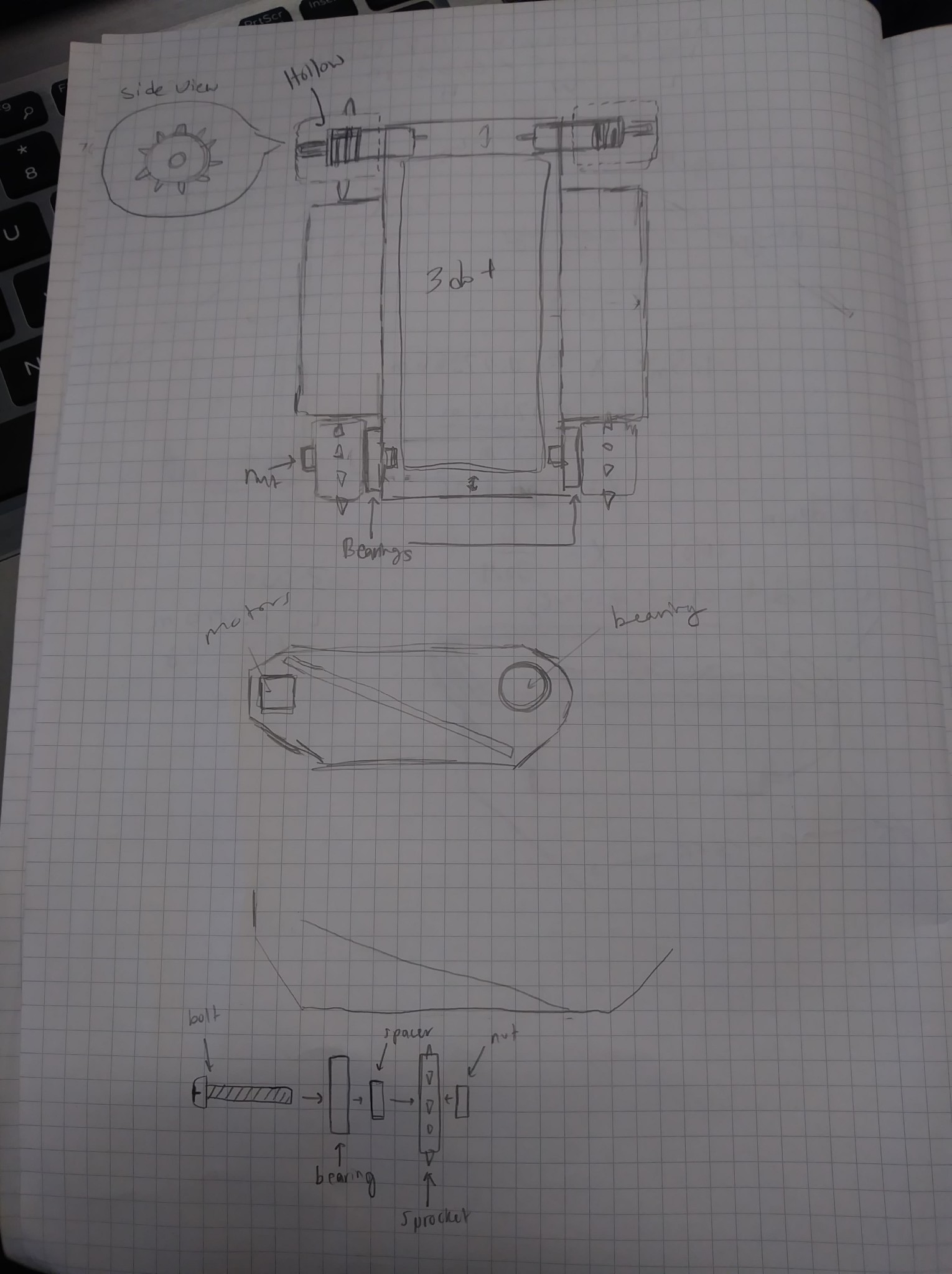
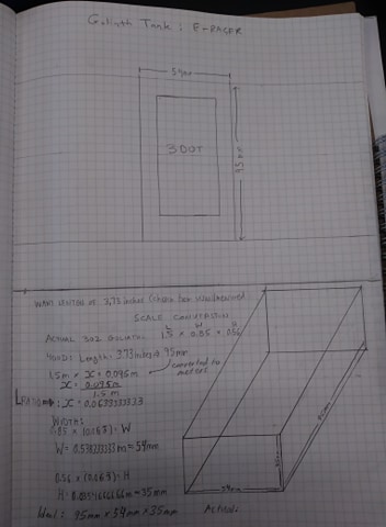
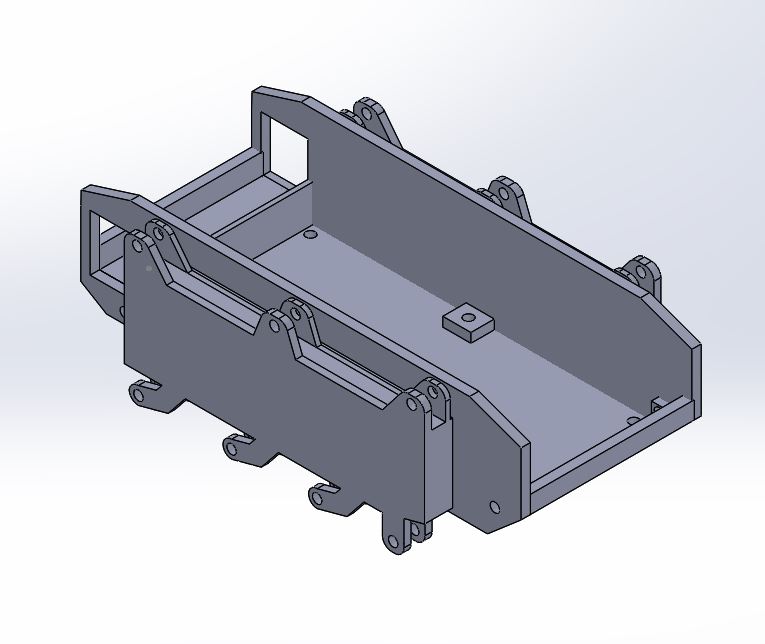
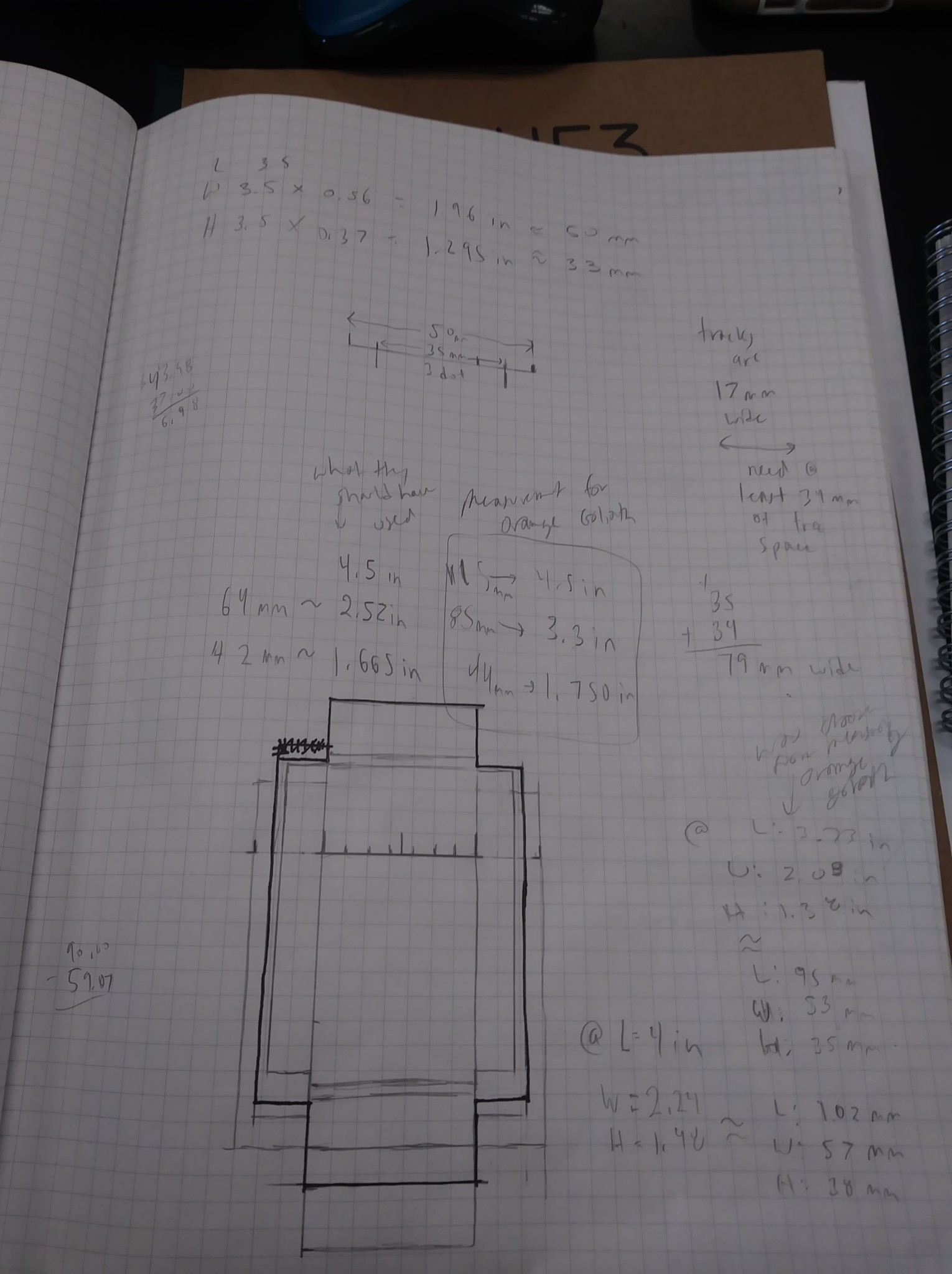
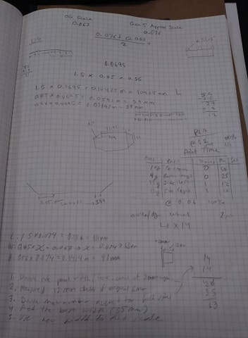
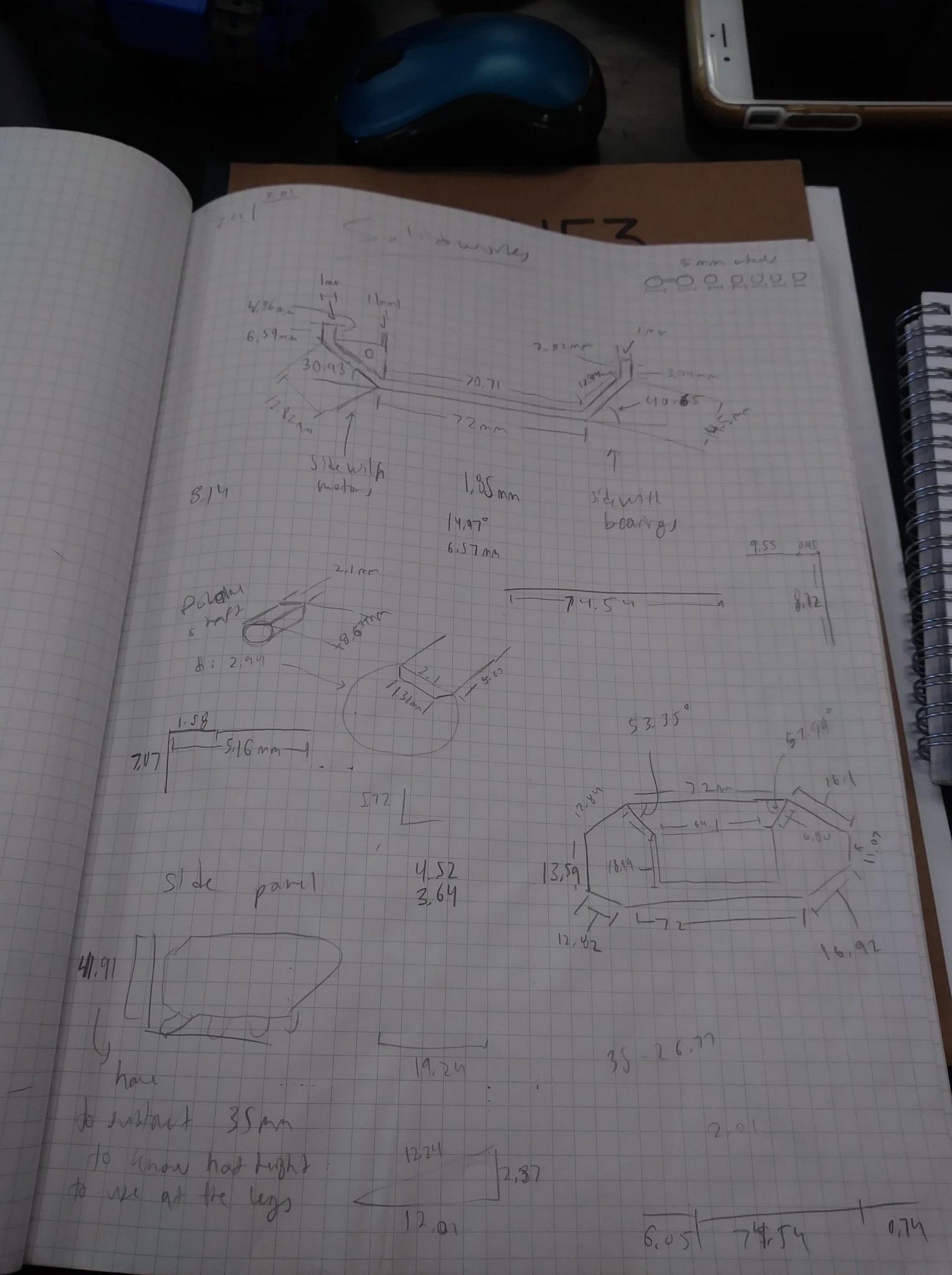
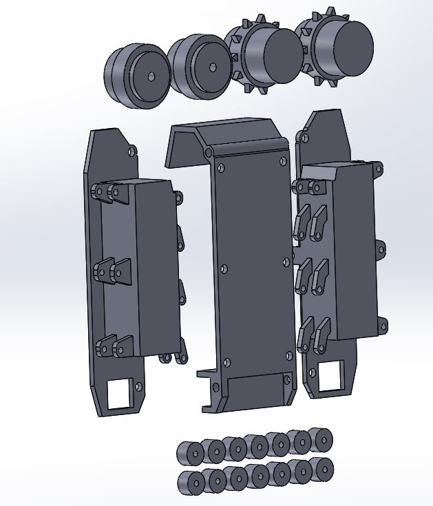
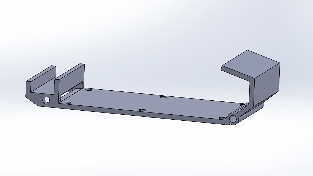
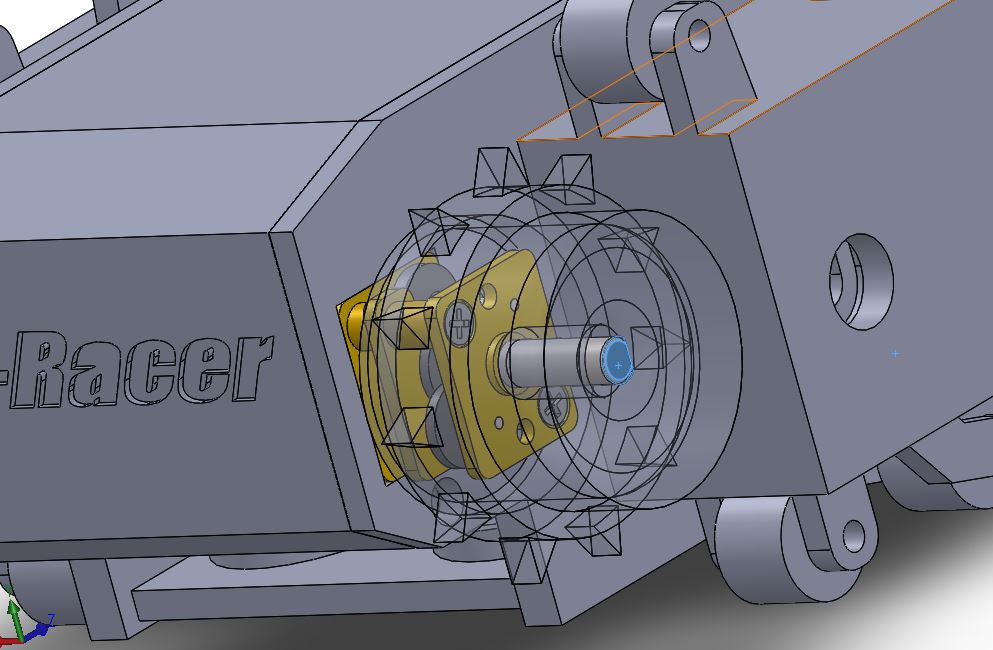
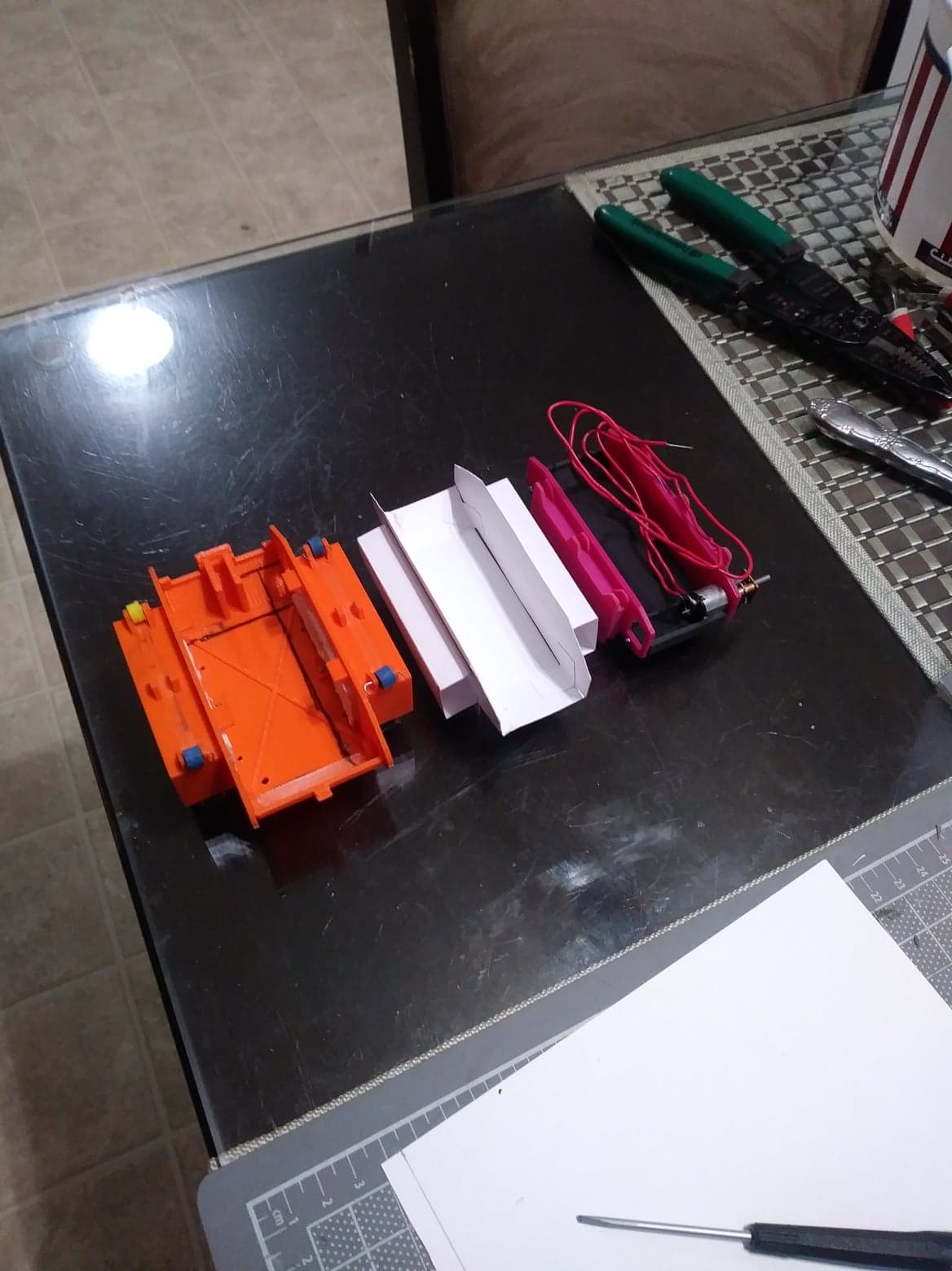
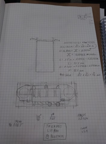
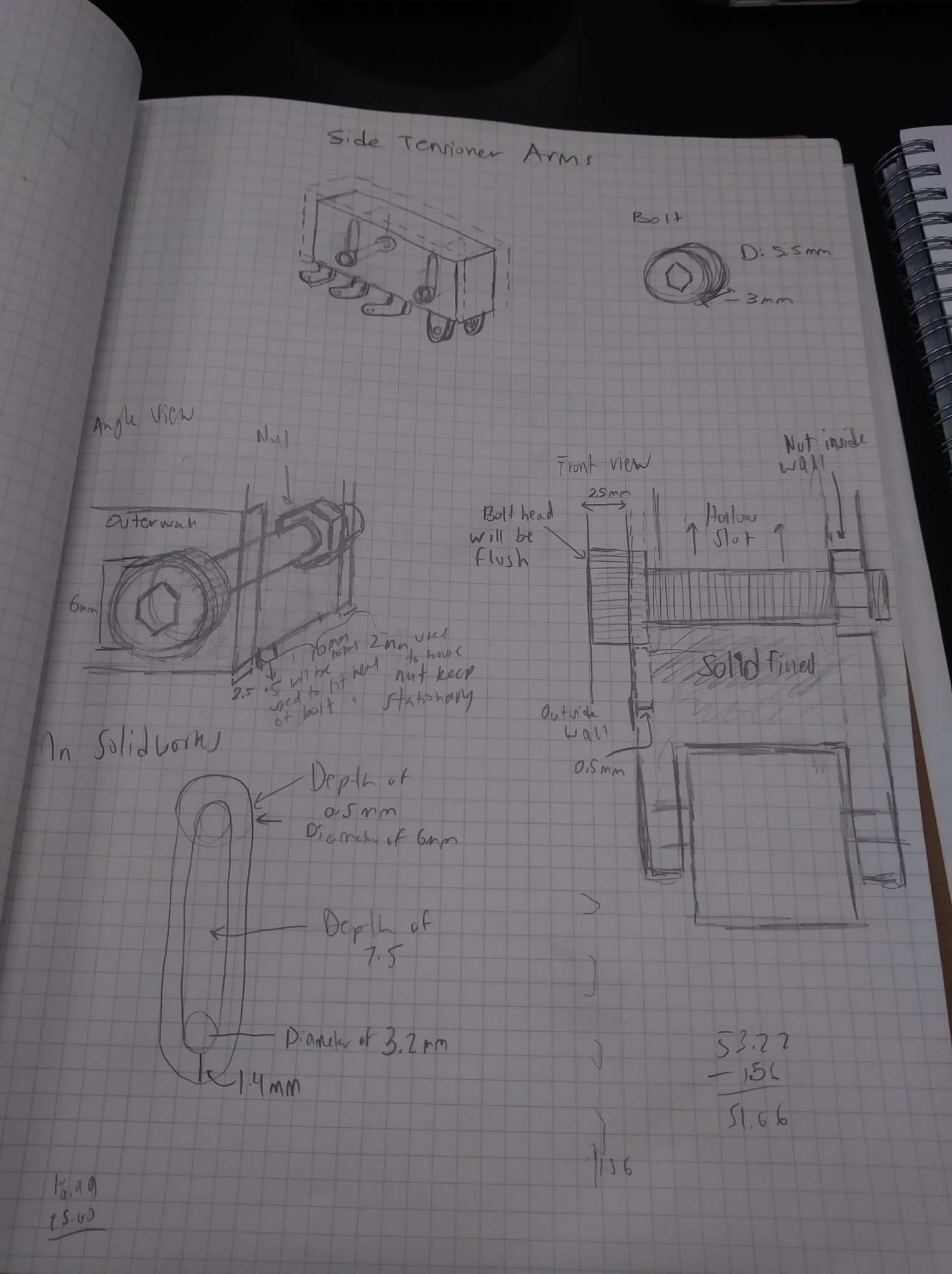
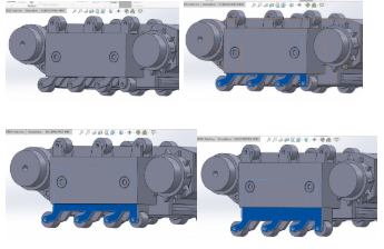
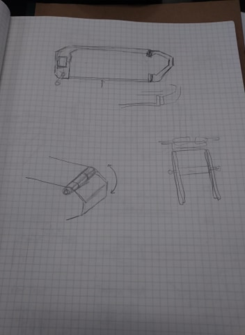
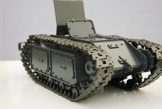
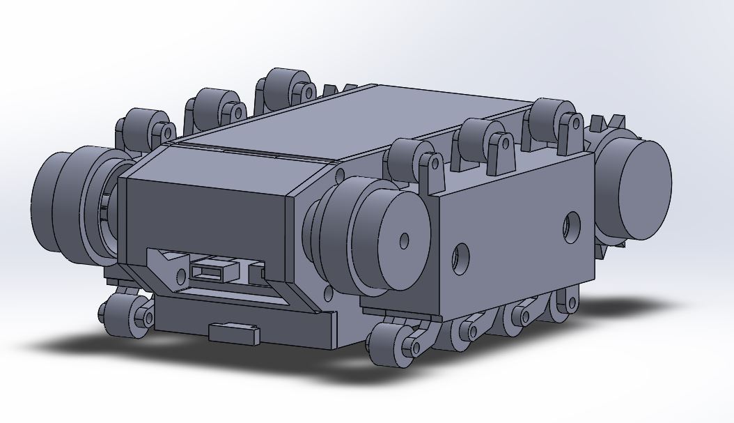

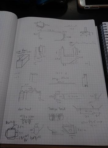
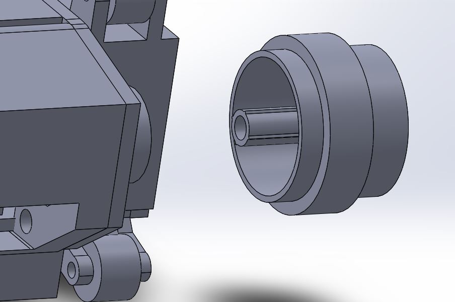
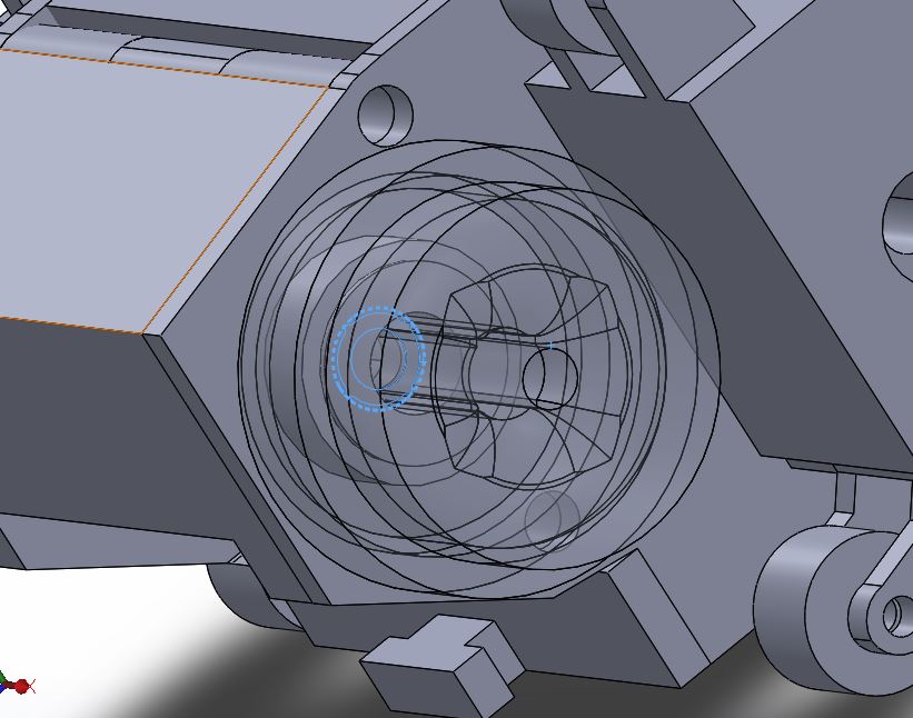
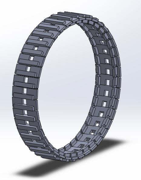
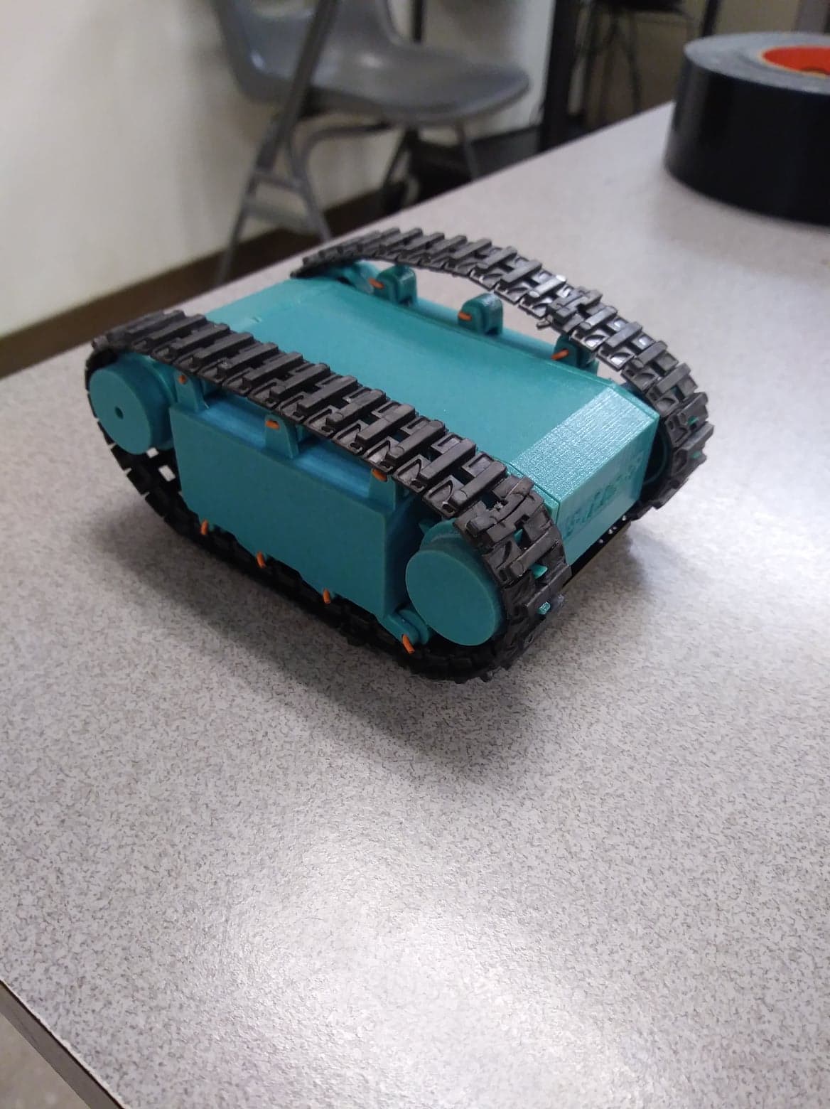
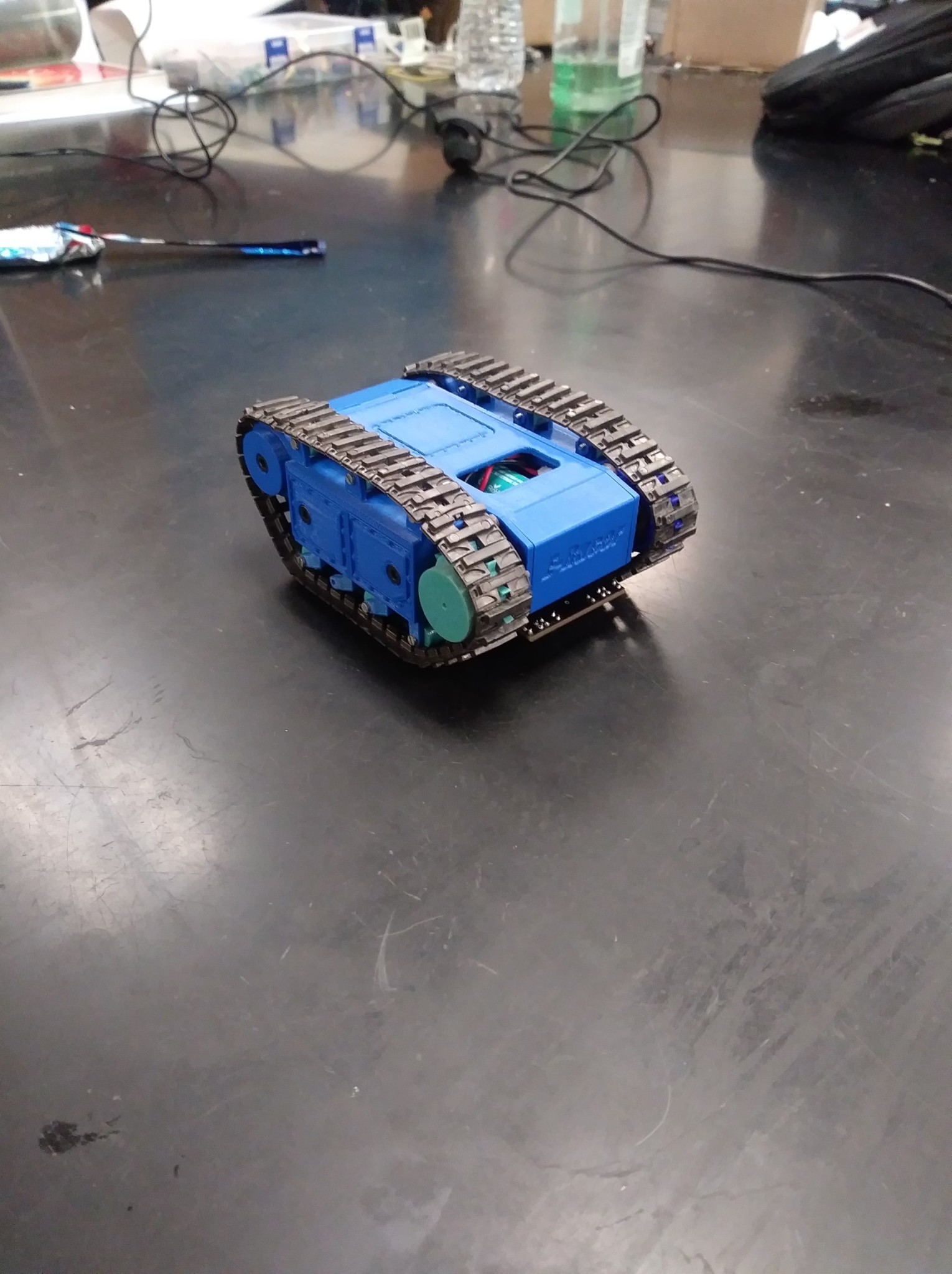
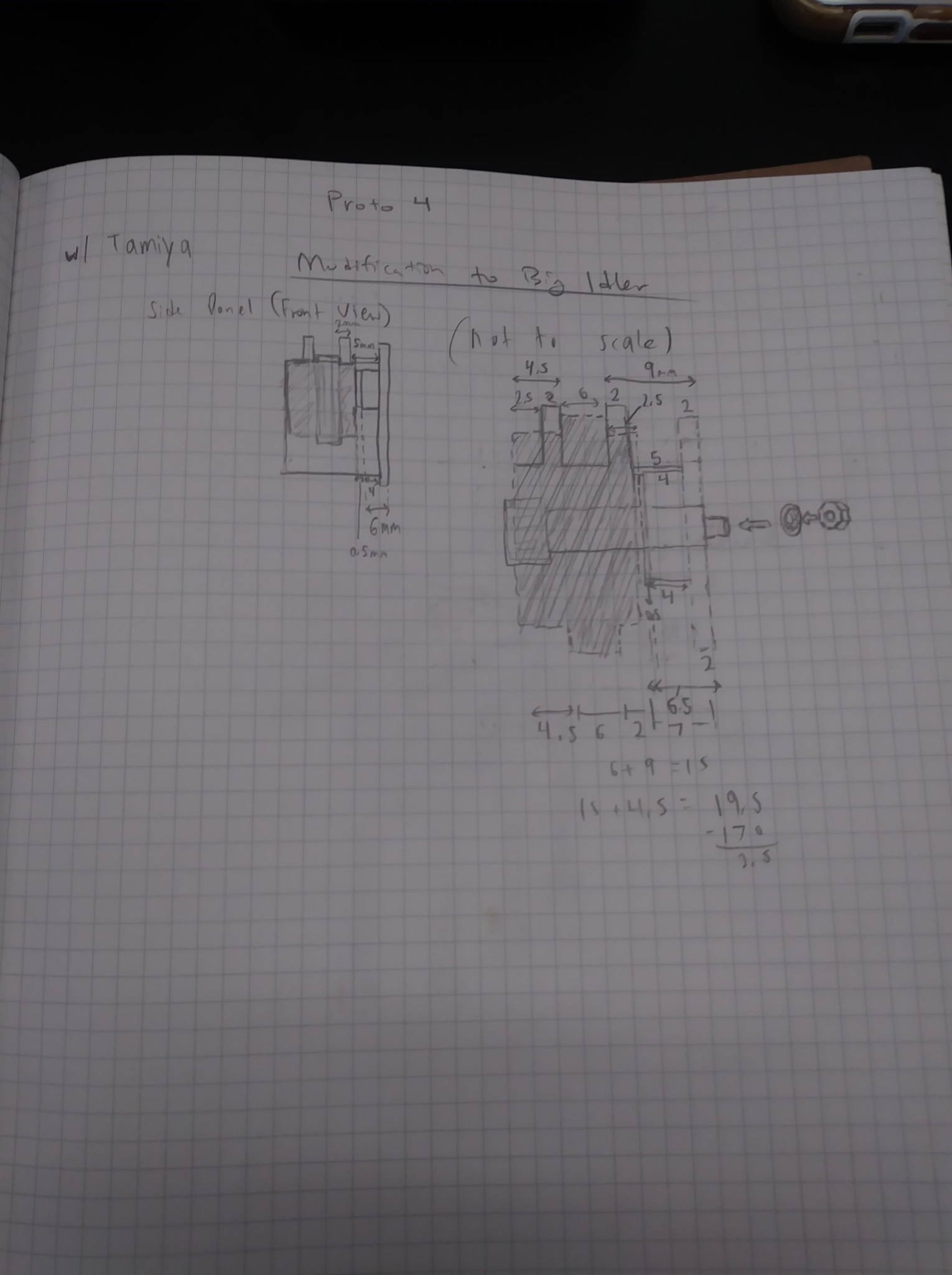
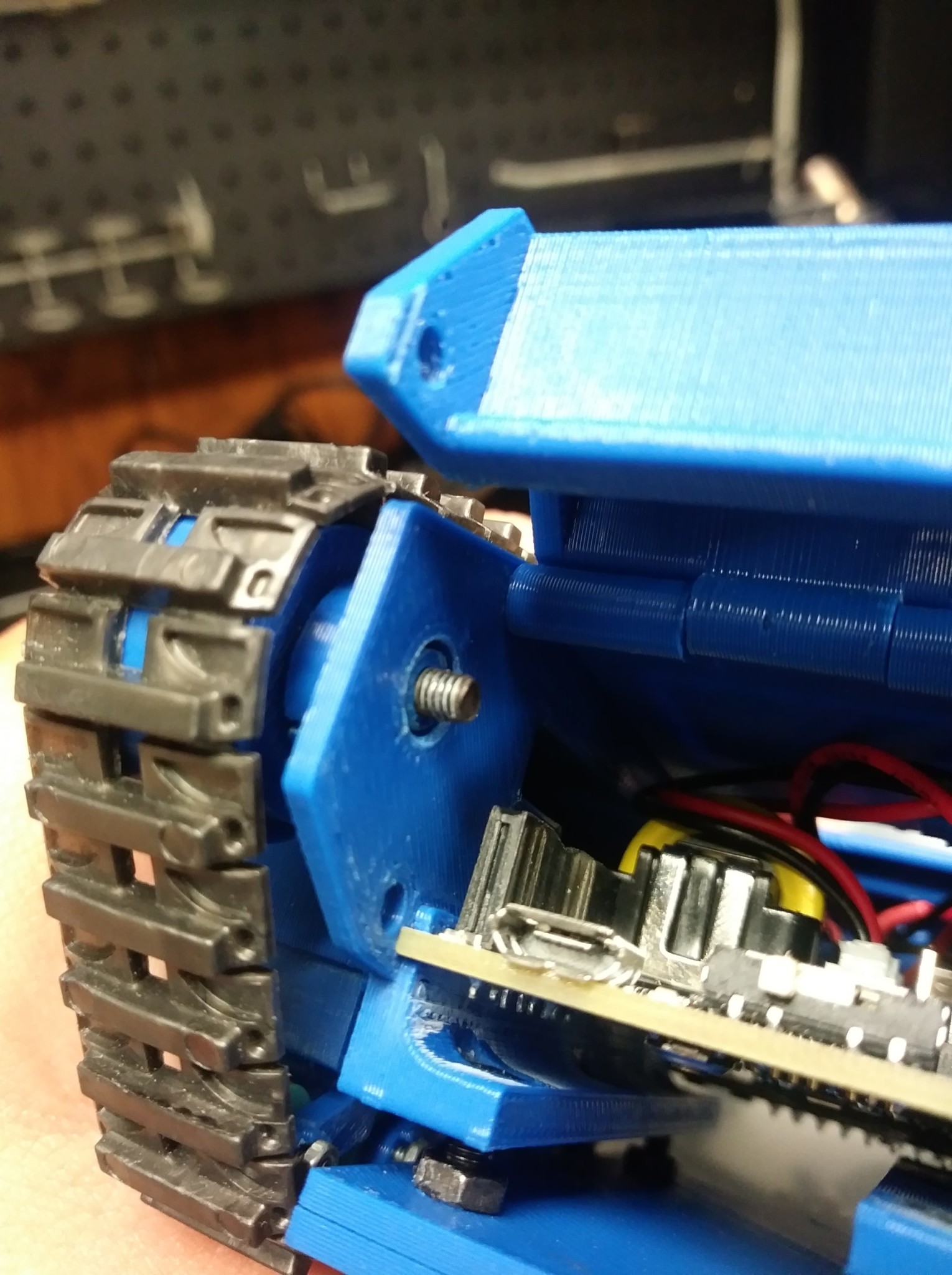
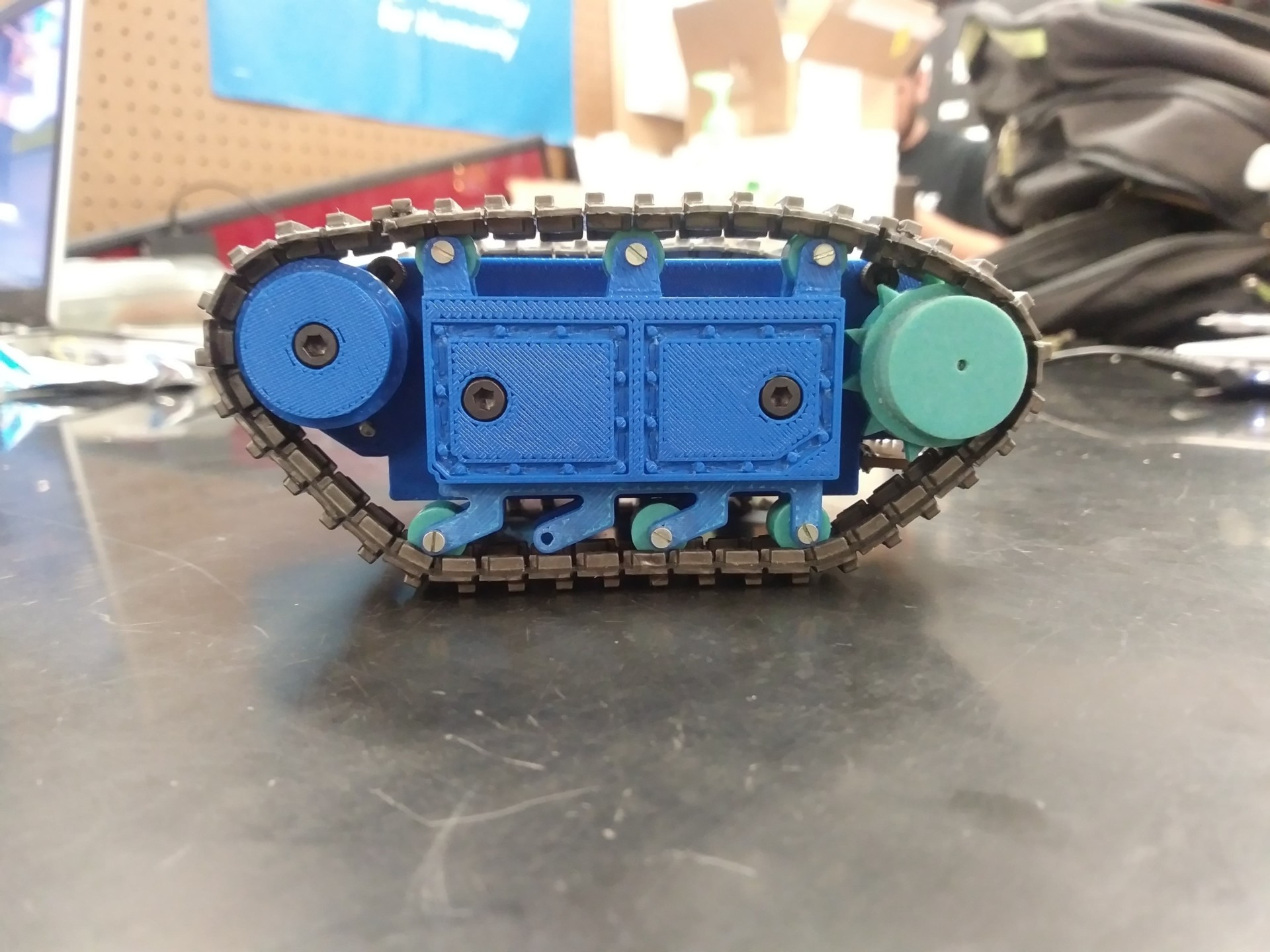

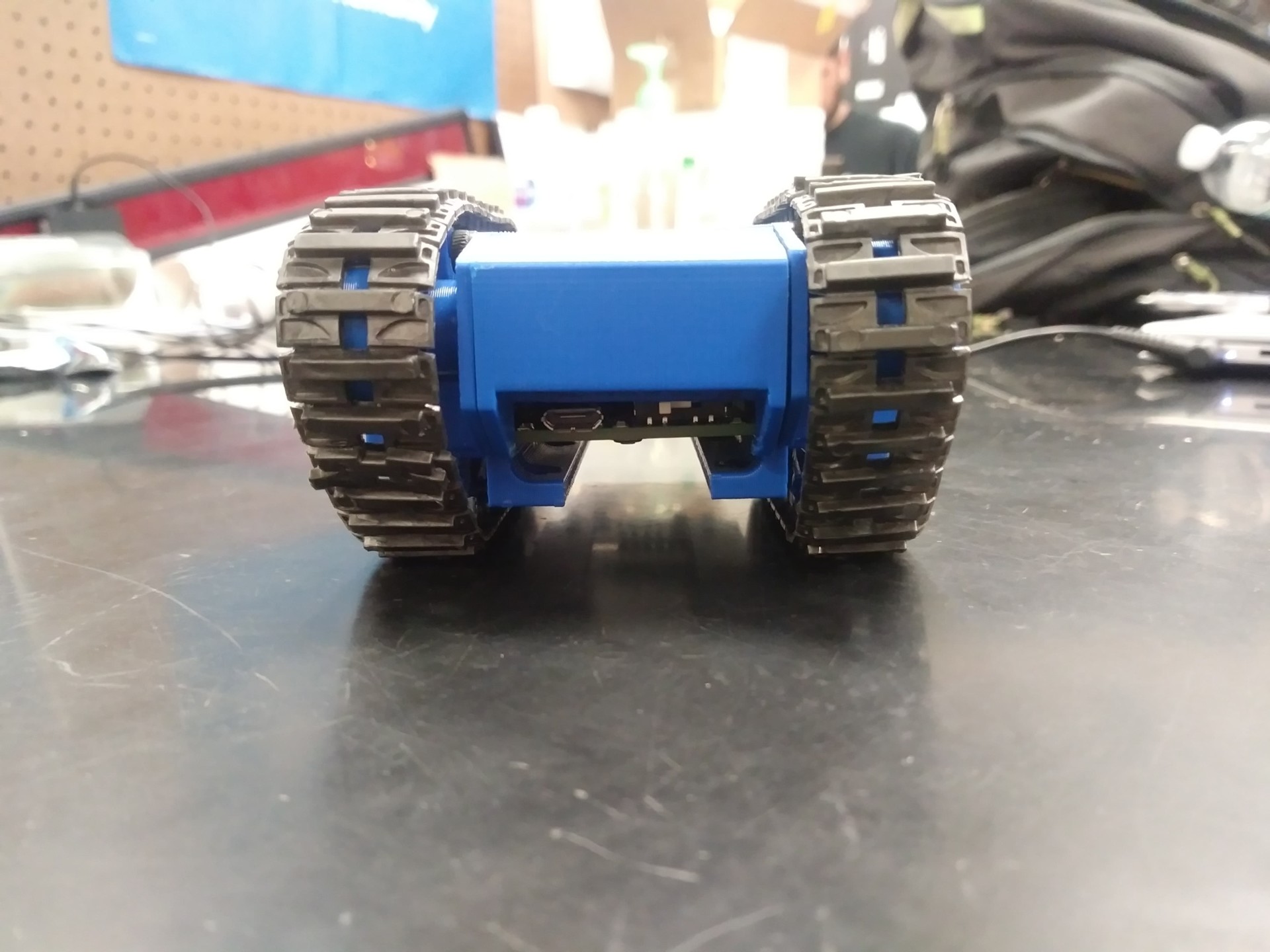
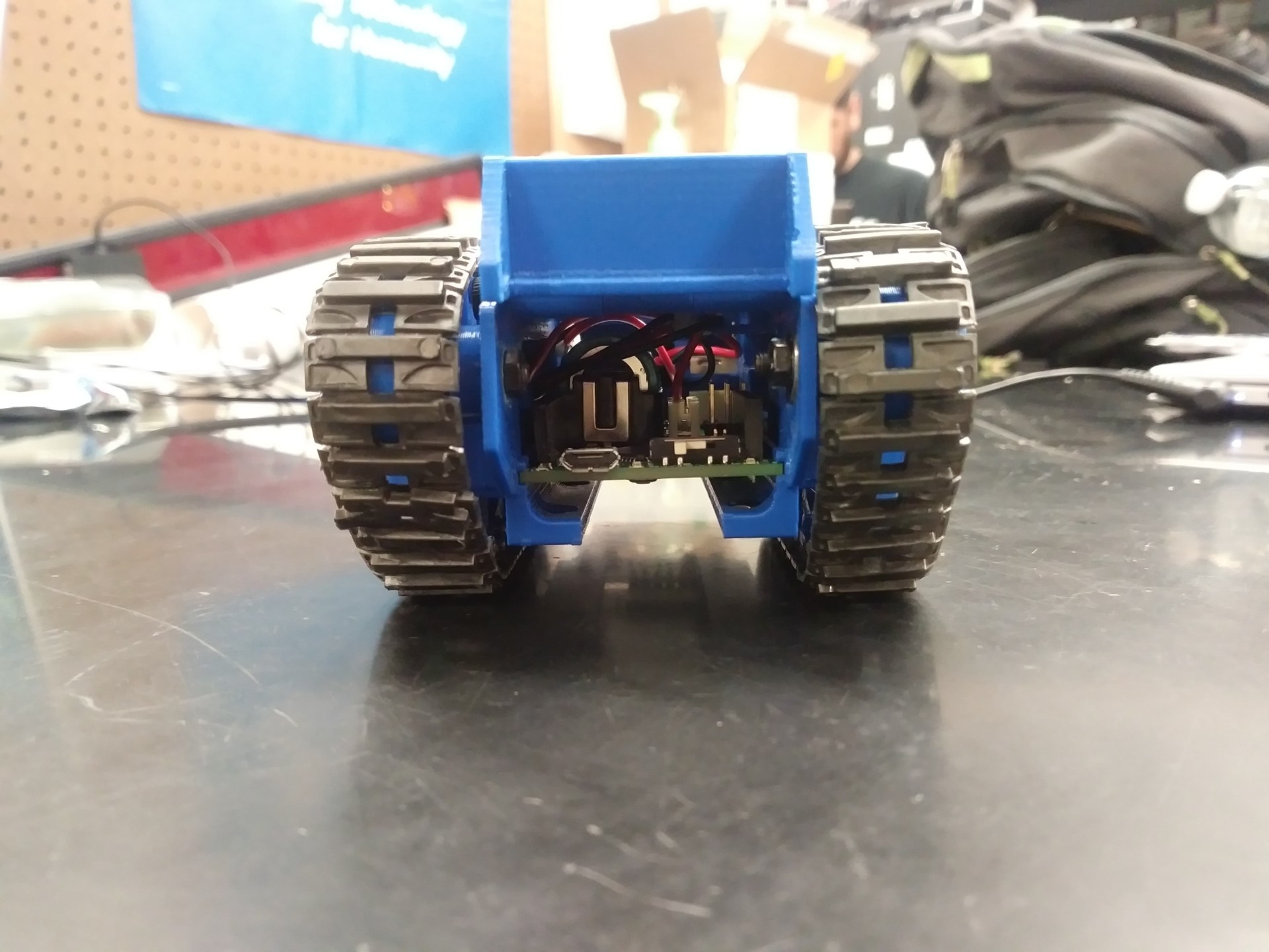
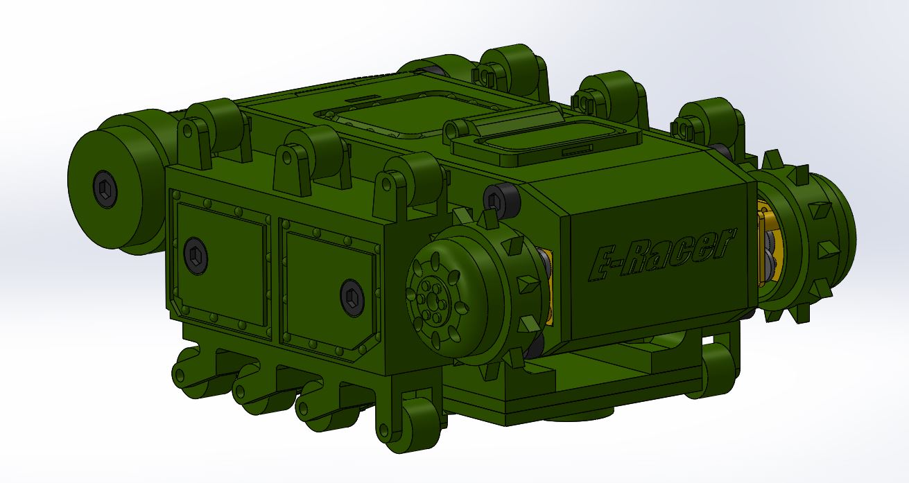
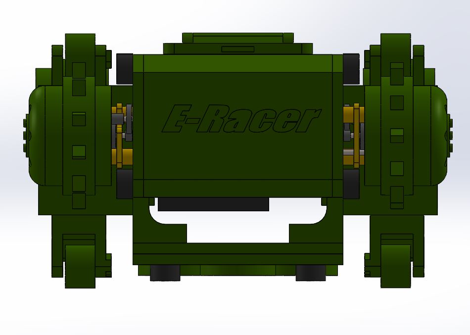
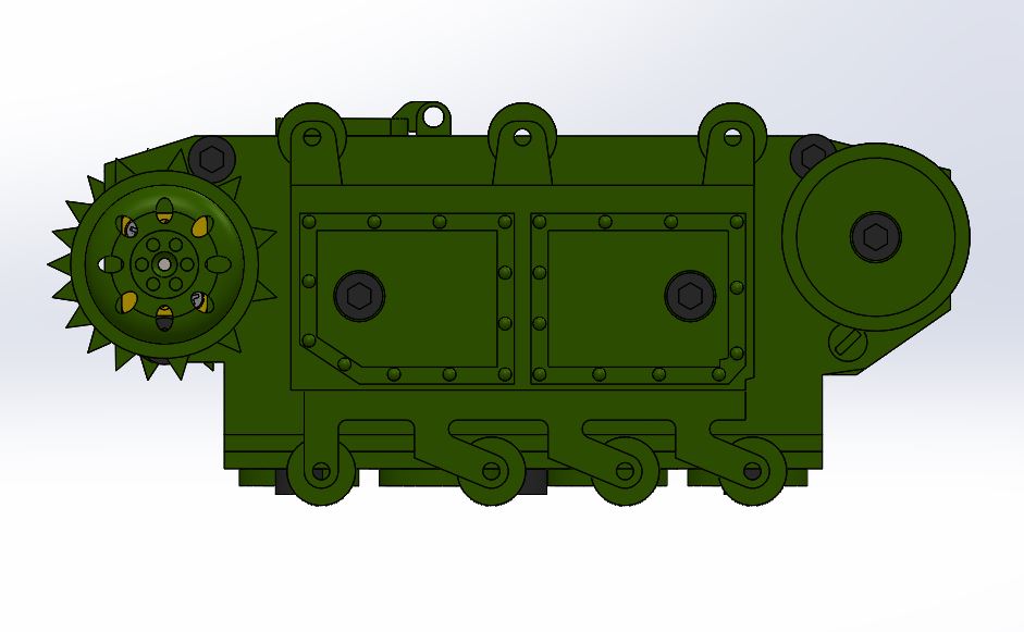
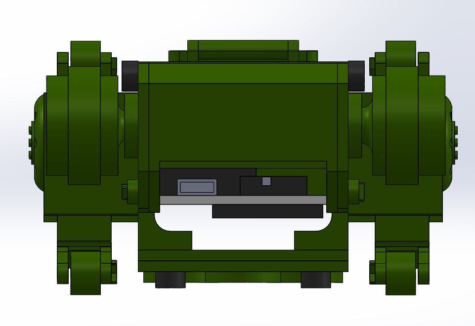
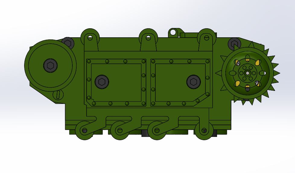
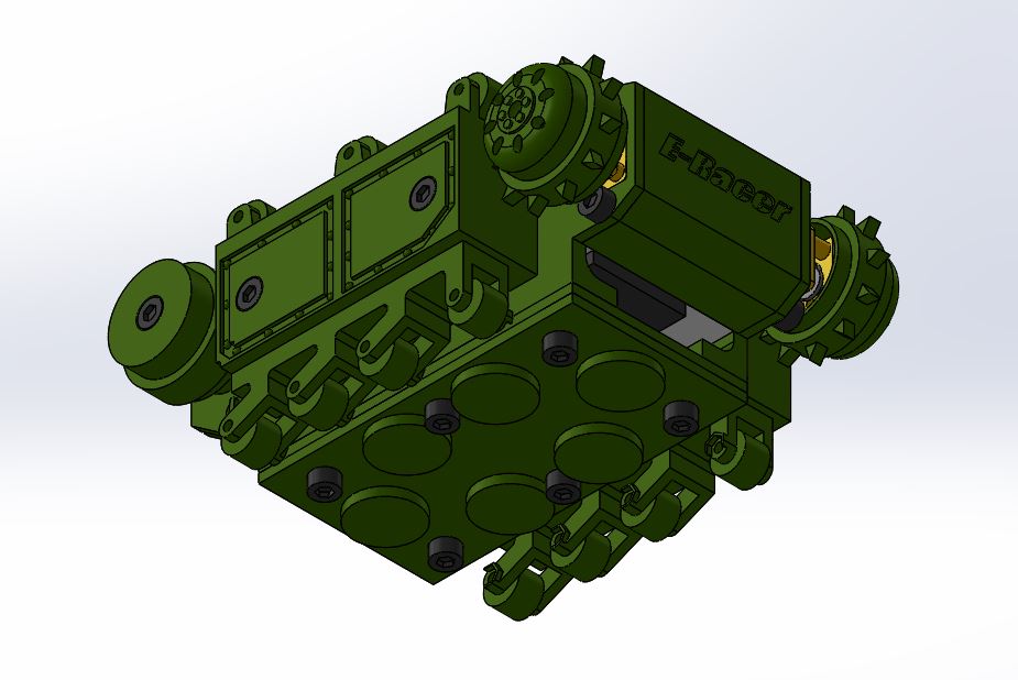
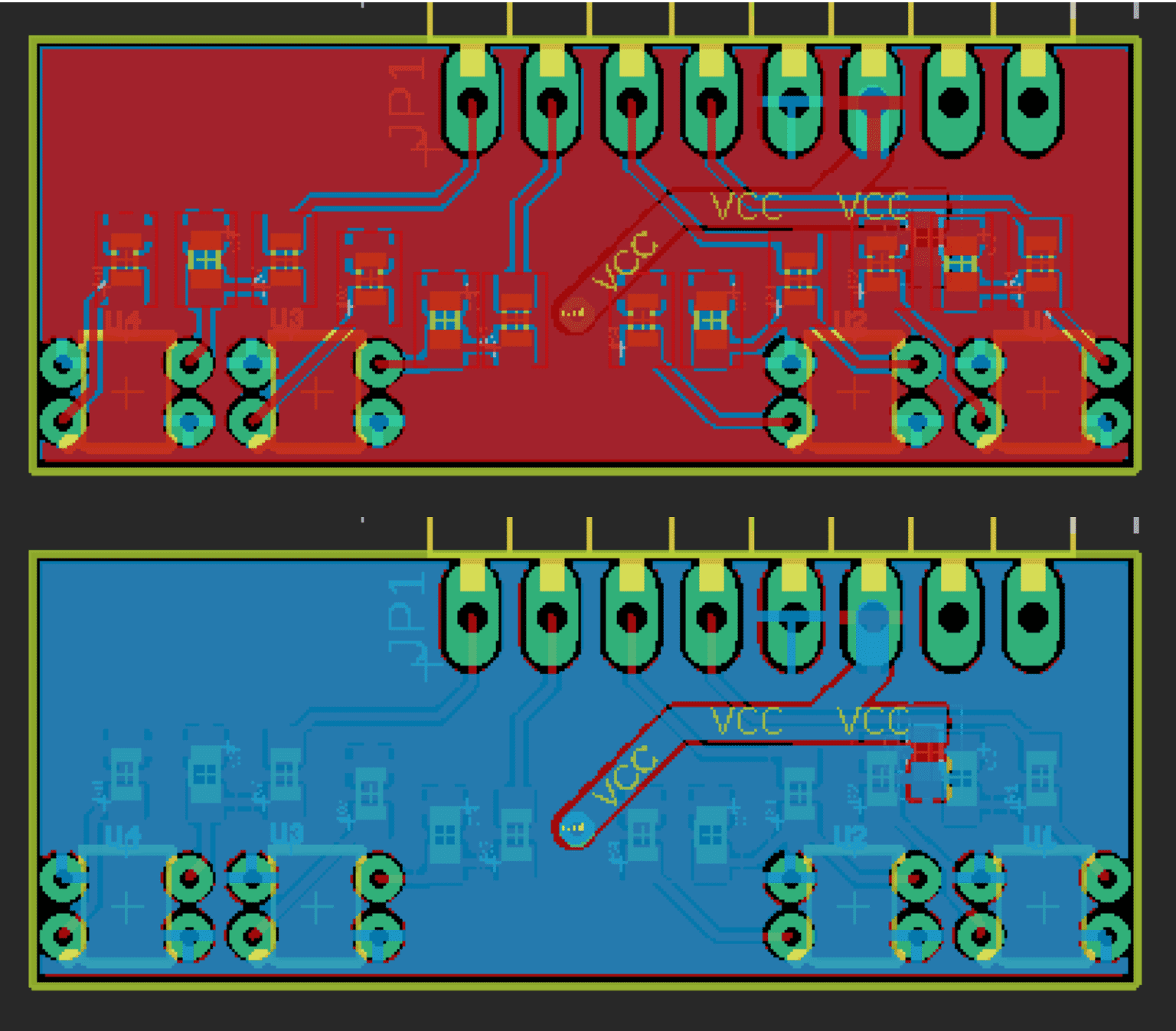
![Figure 6 Sparkfun QRE1113 Digital Breakout Board: Photo and Schematics [1]](https://www.arxterra.com/wp-content/uploads/2019/04/6-1.png)
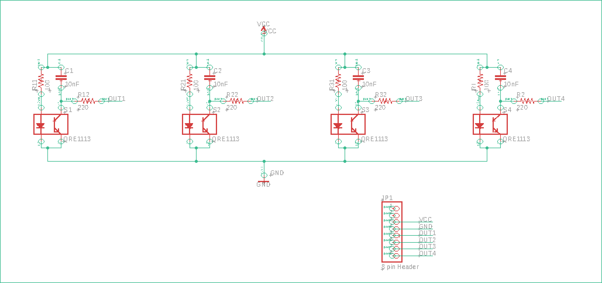
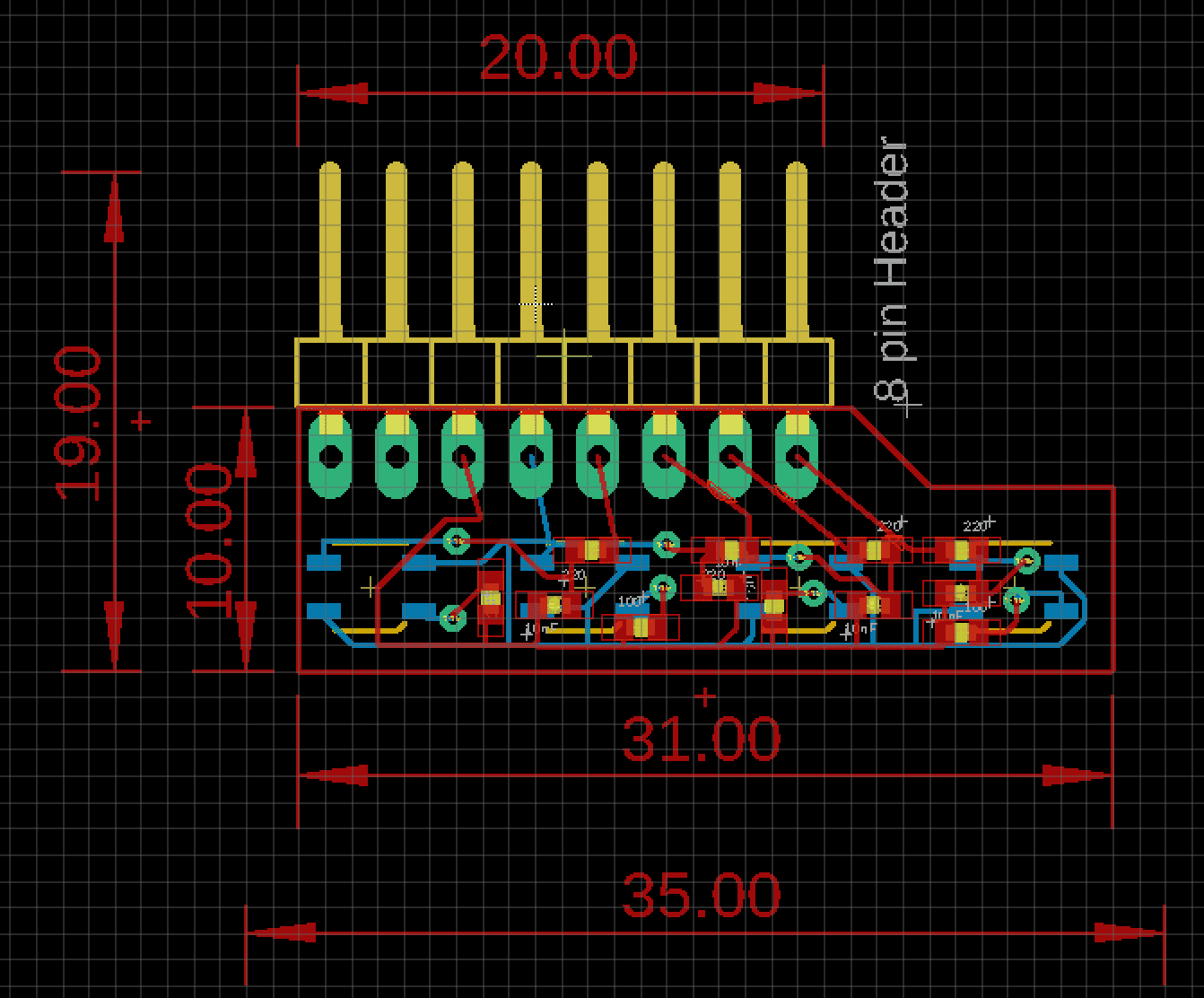
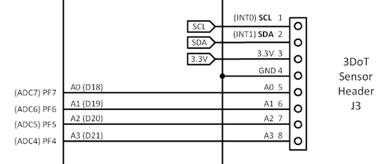
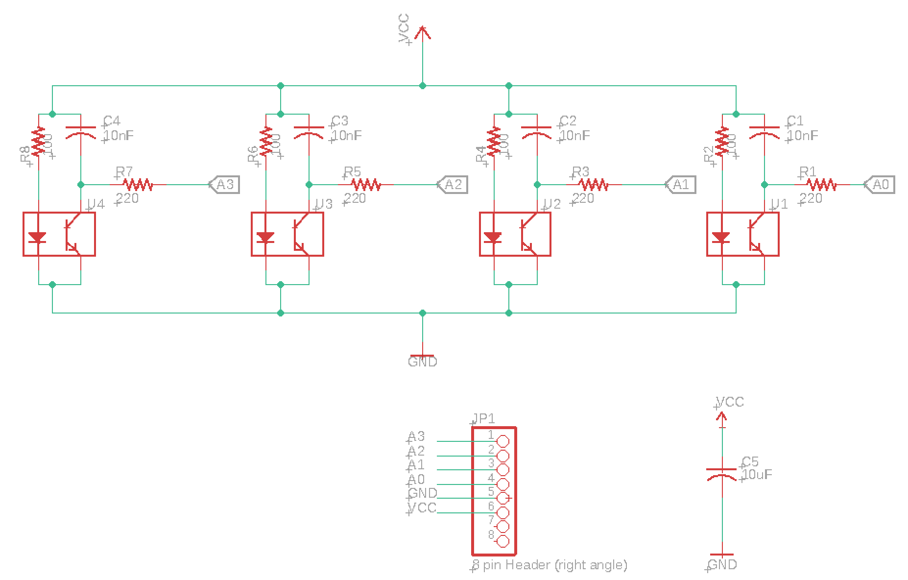

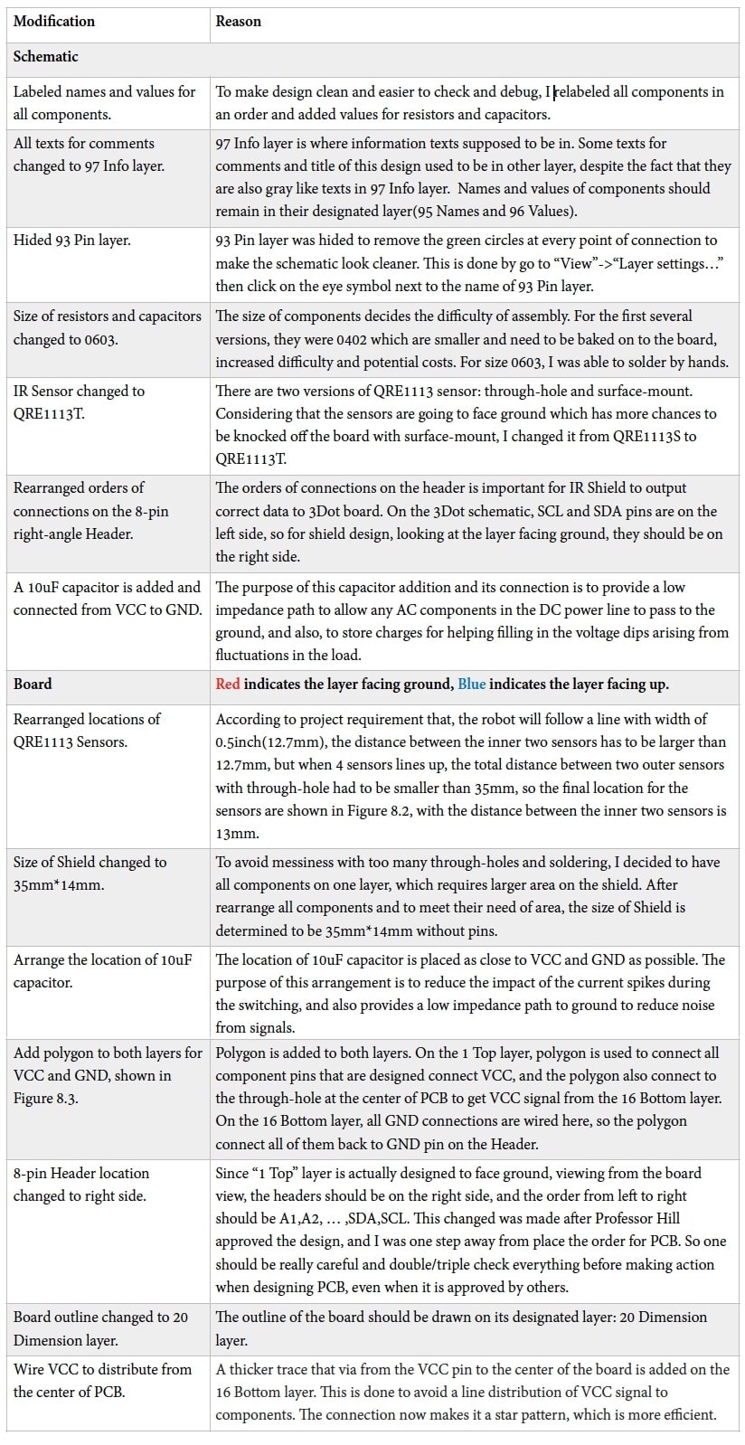
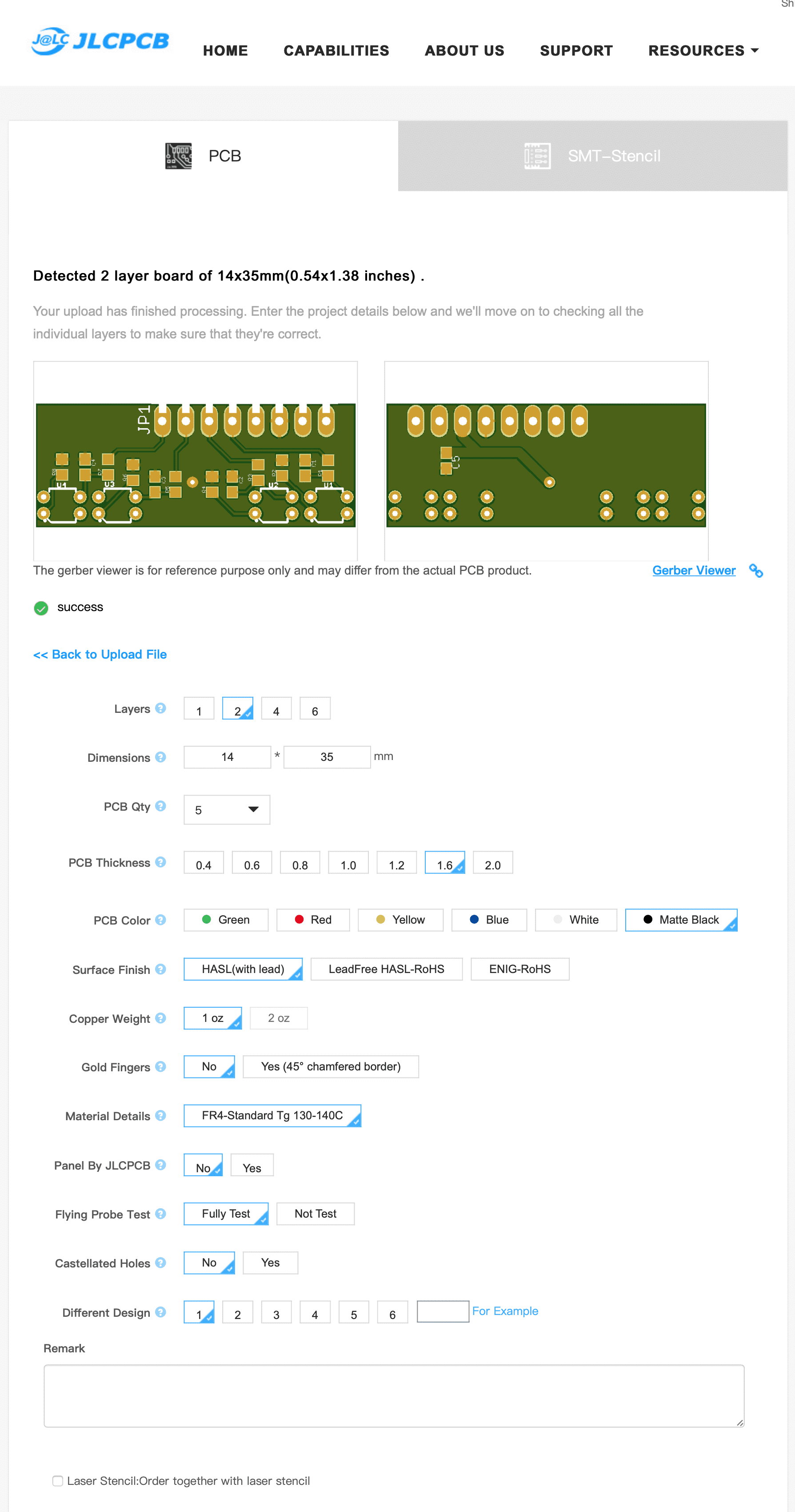
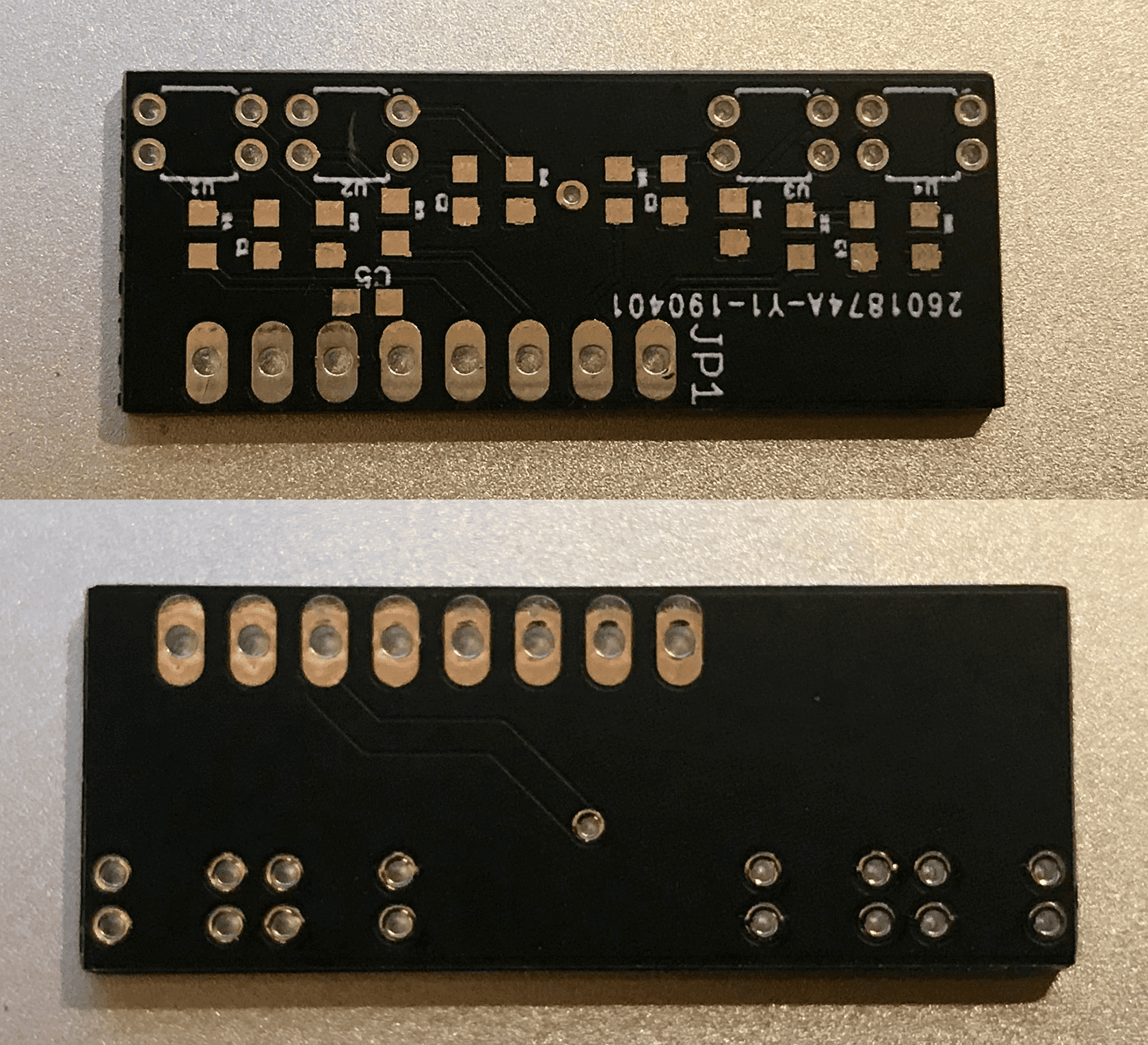
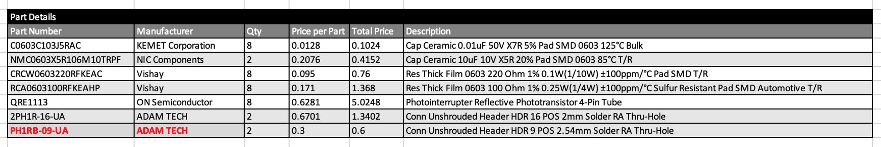
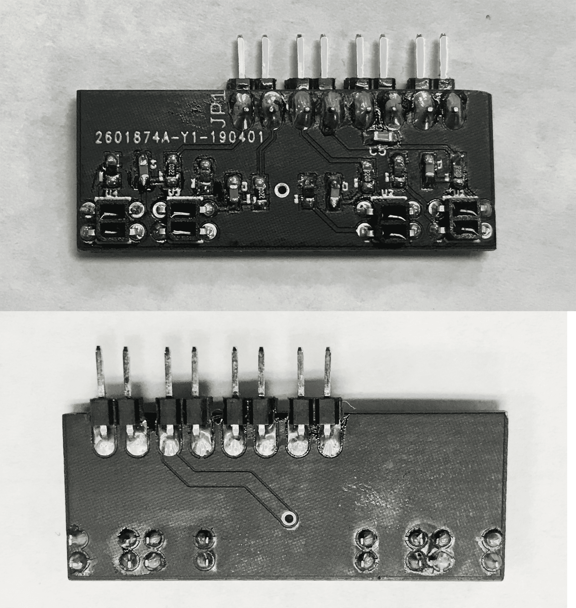
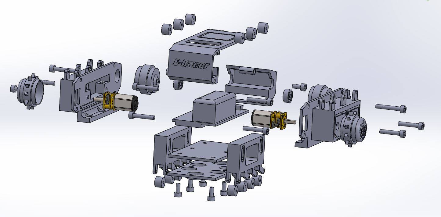
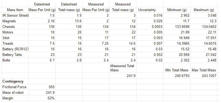
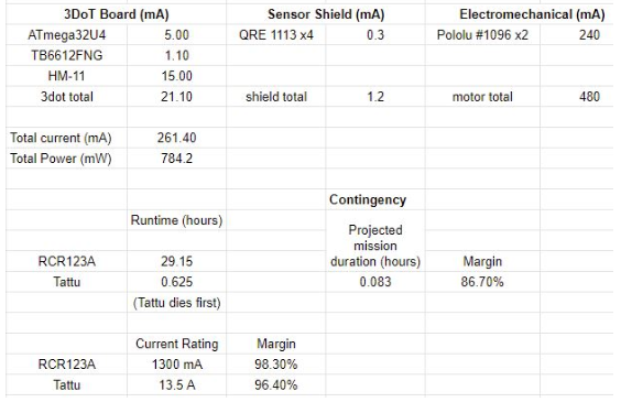
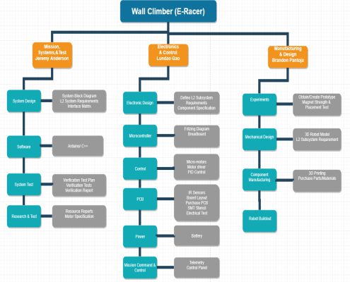
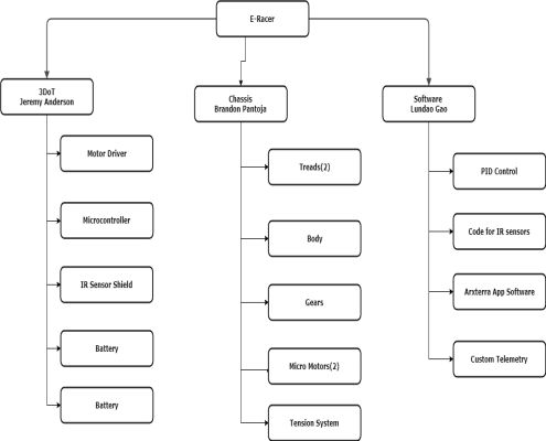
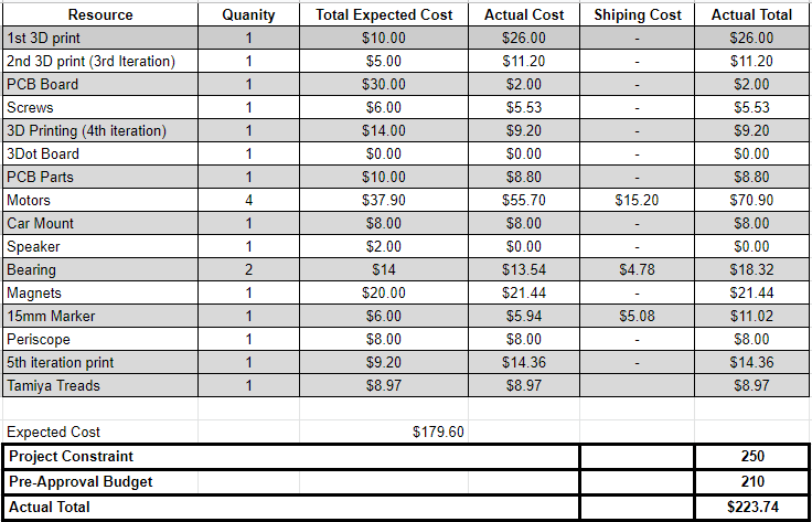
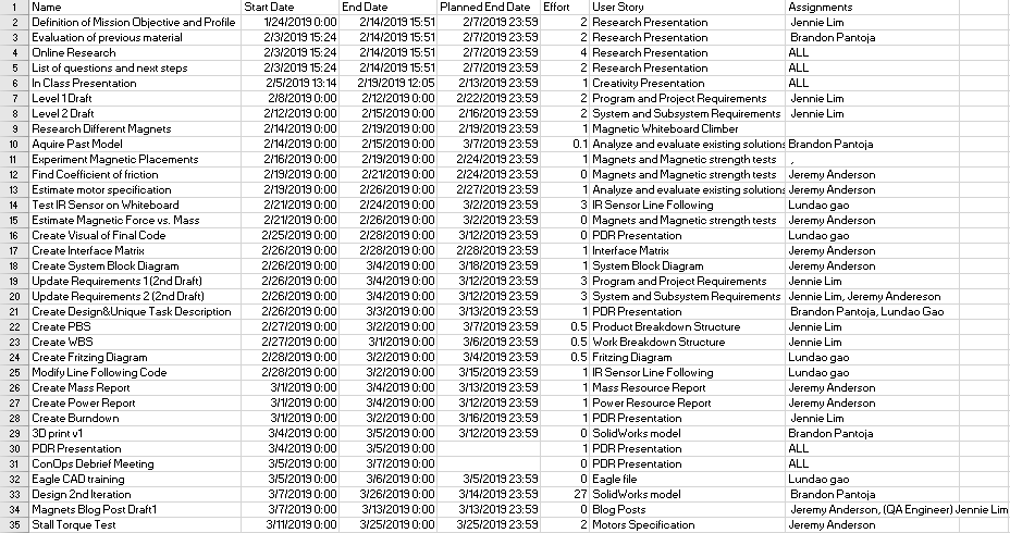
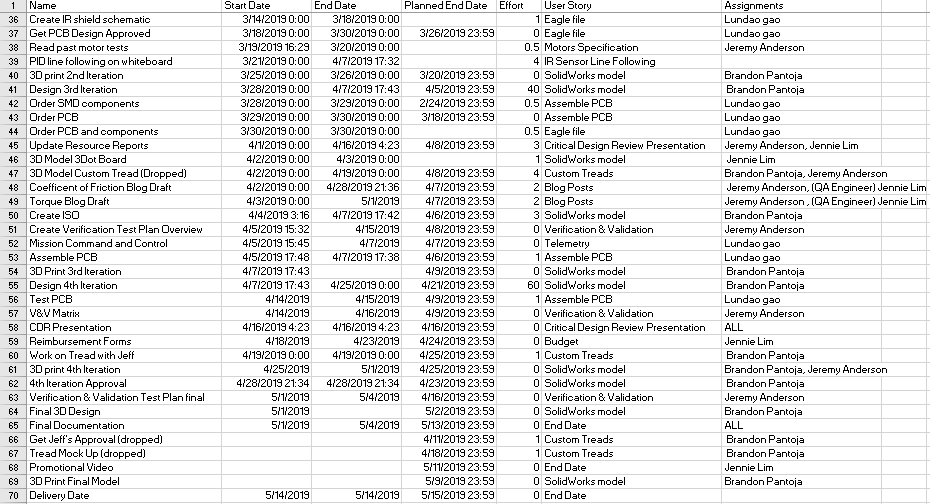
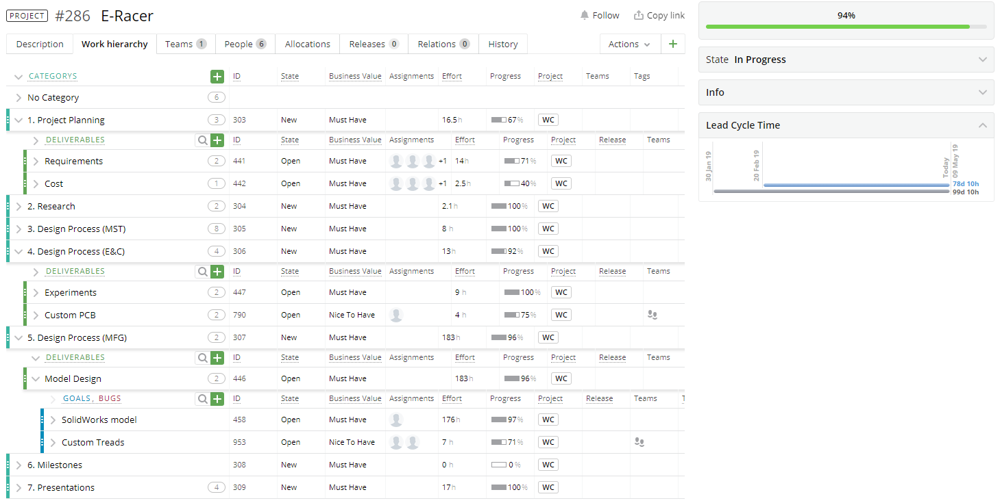
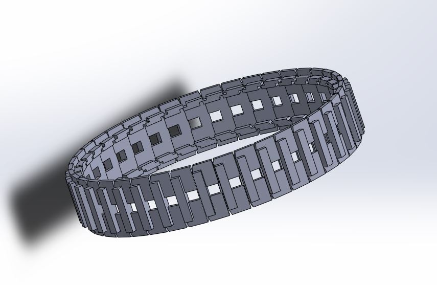
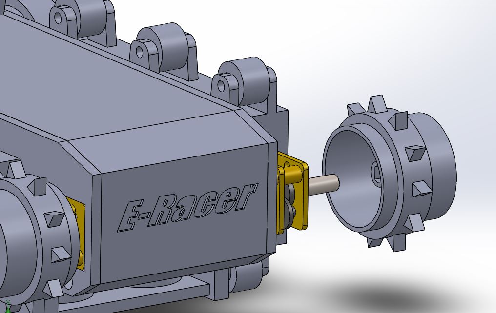
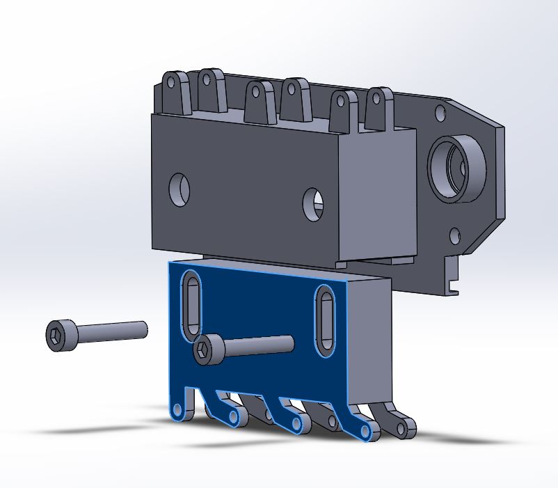
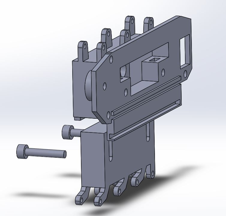
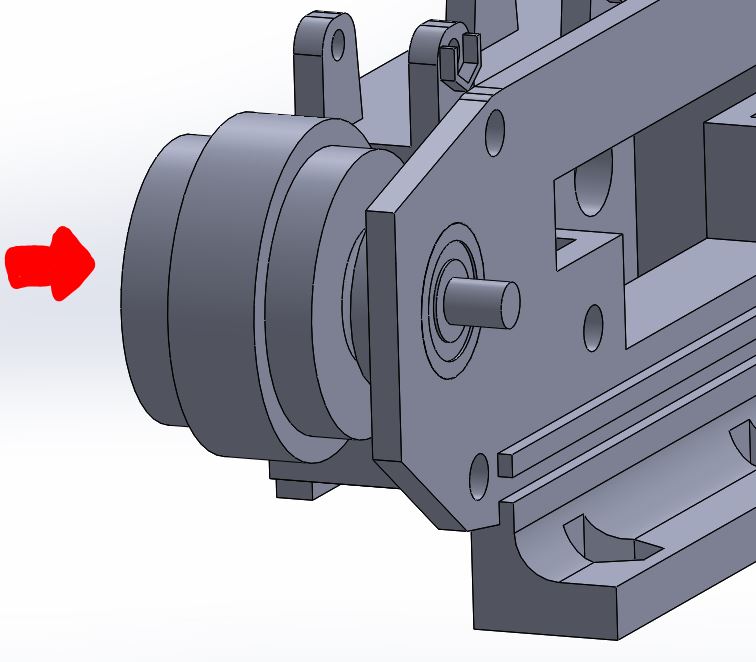
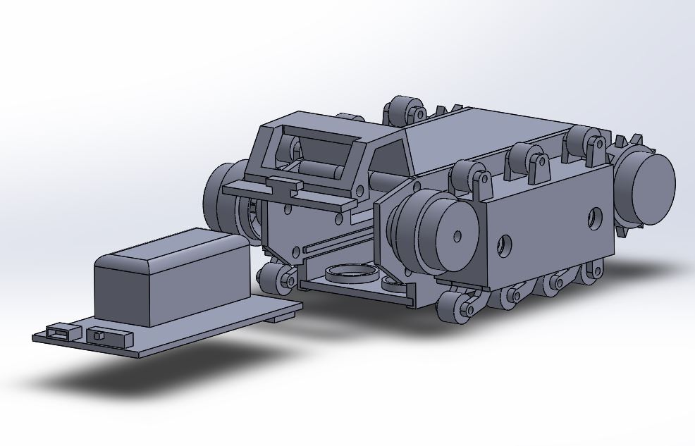
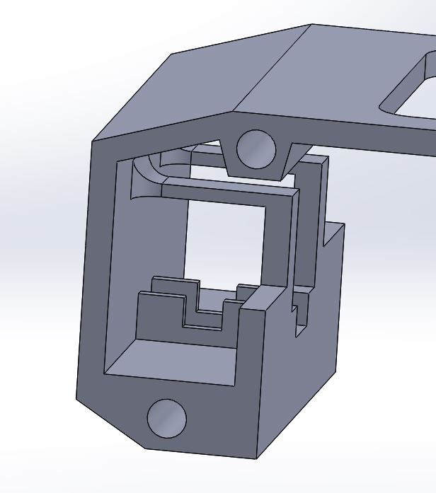
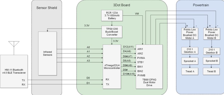
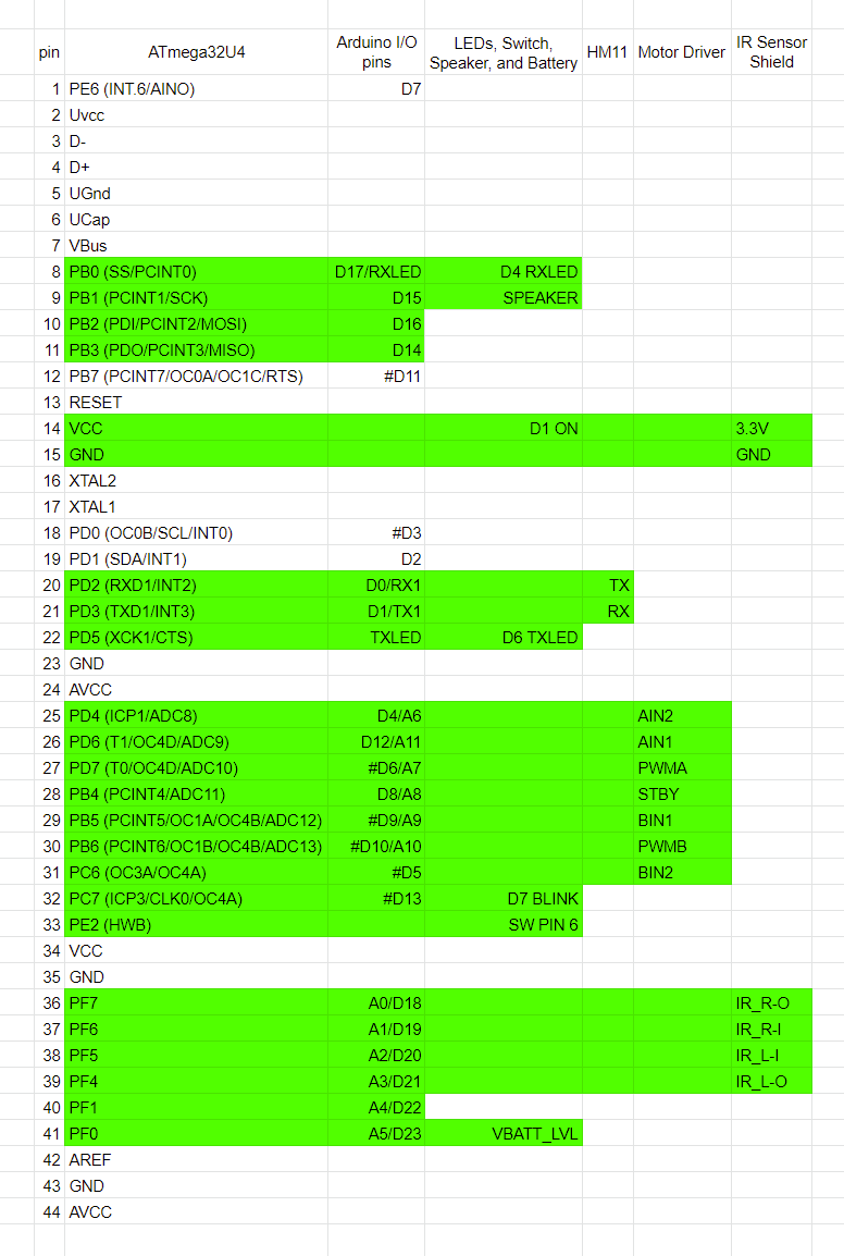
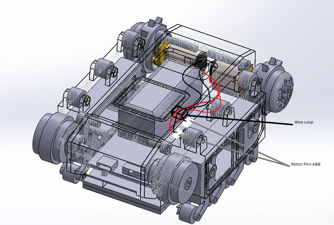
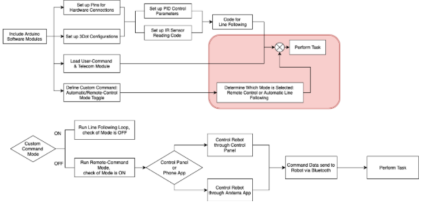
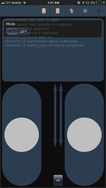
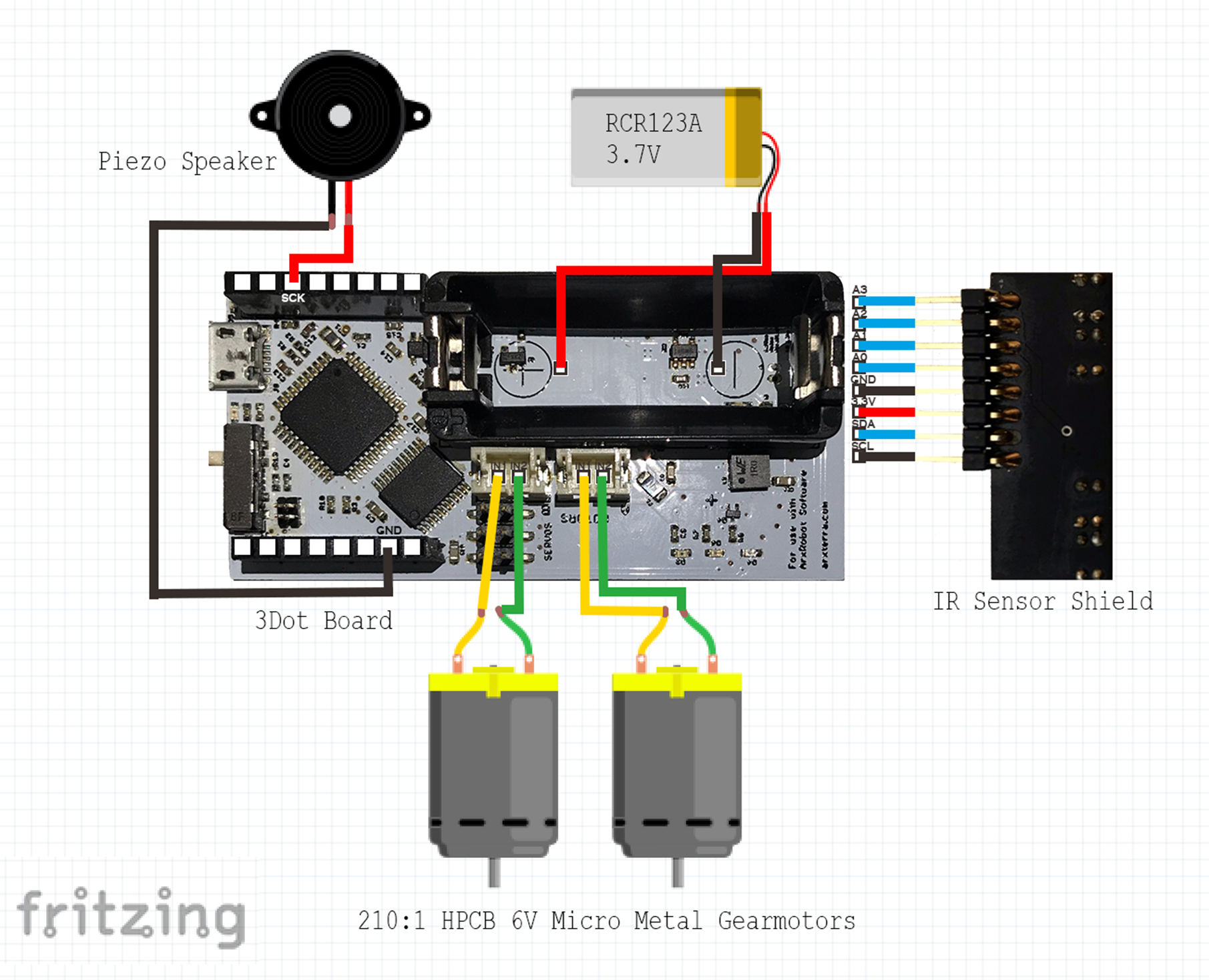
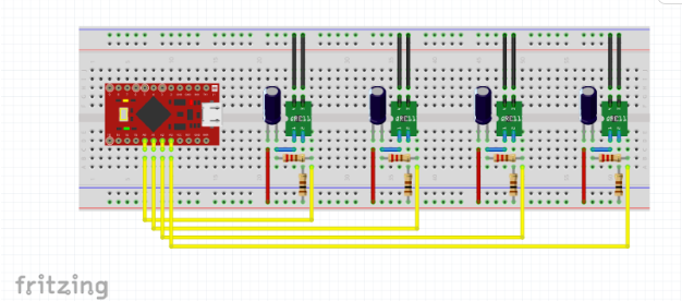
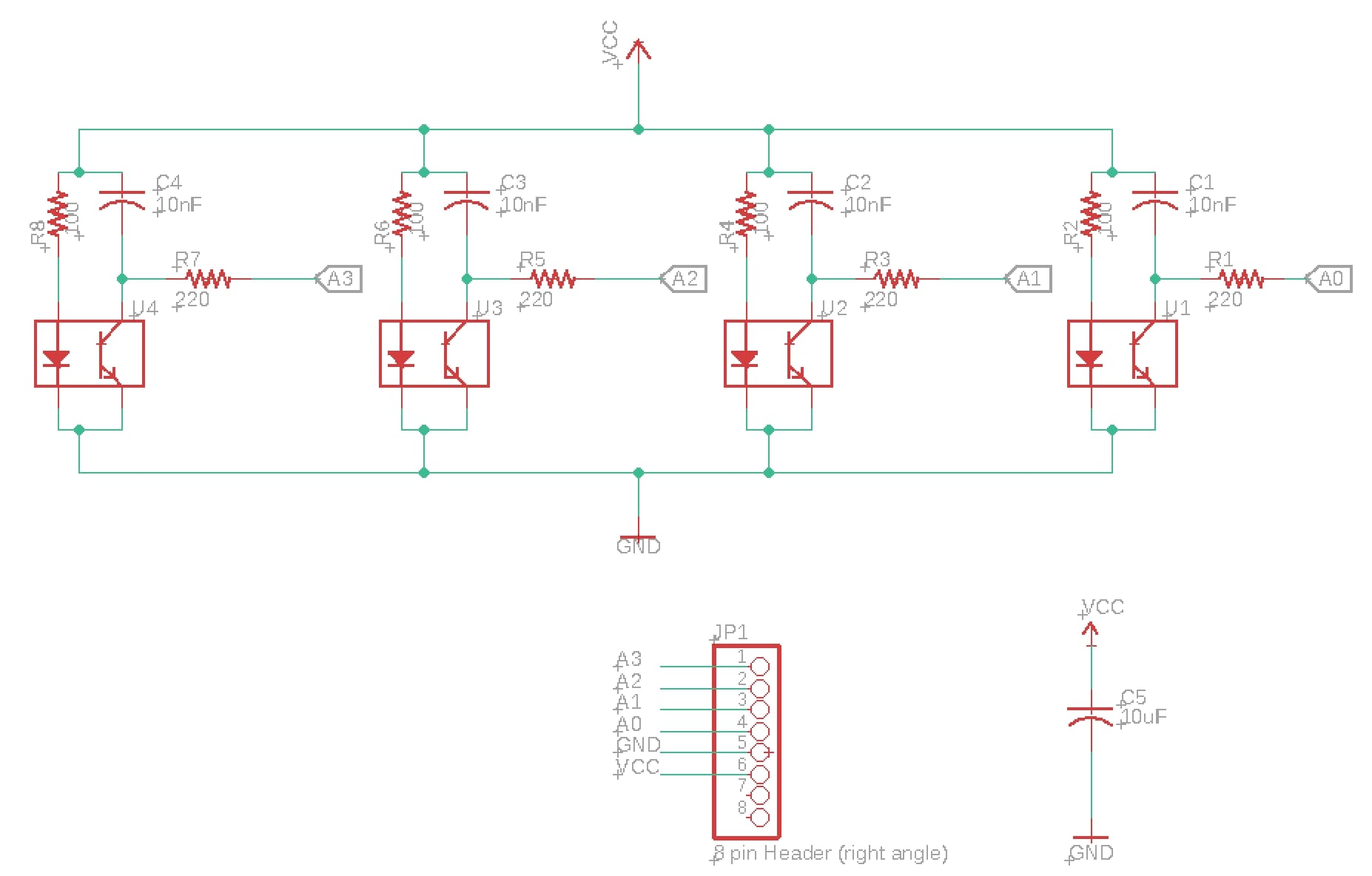
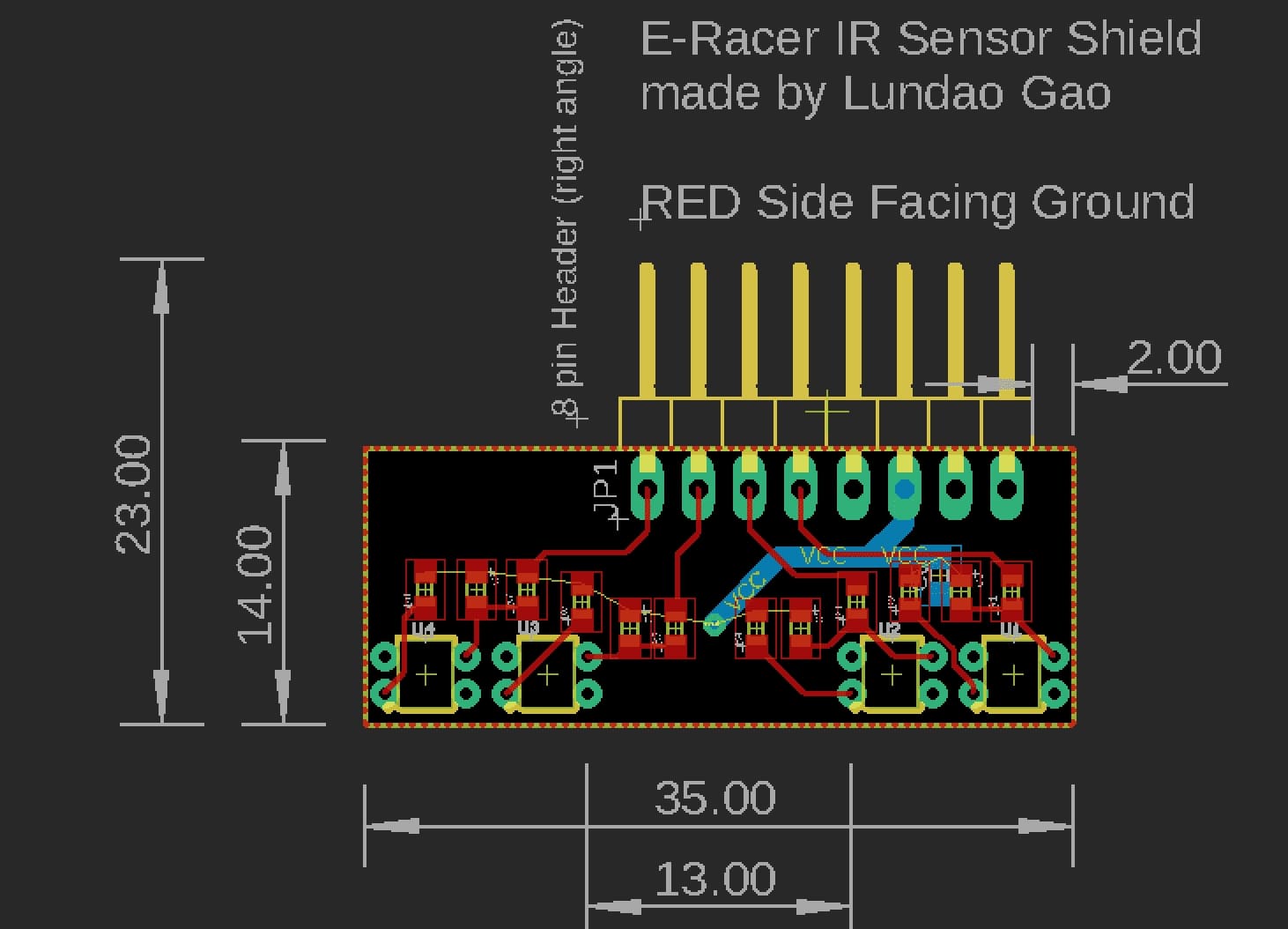
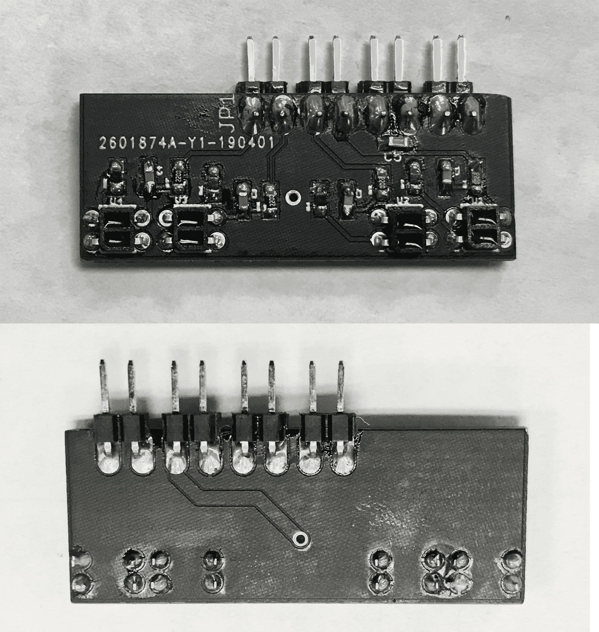
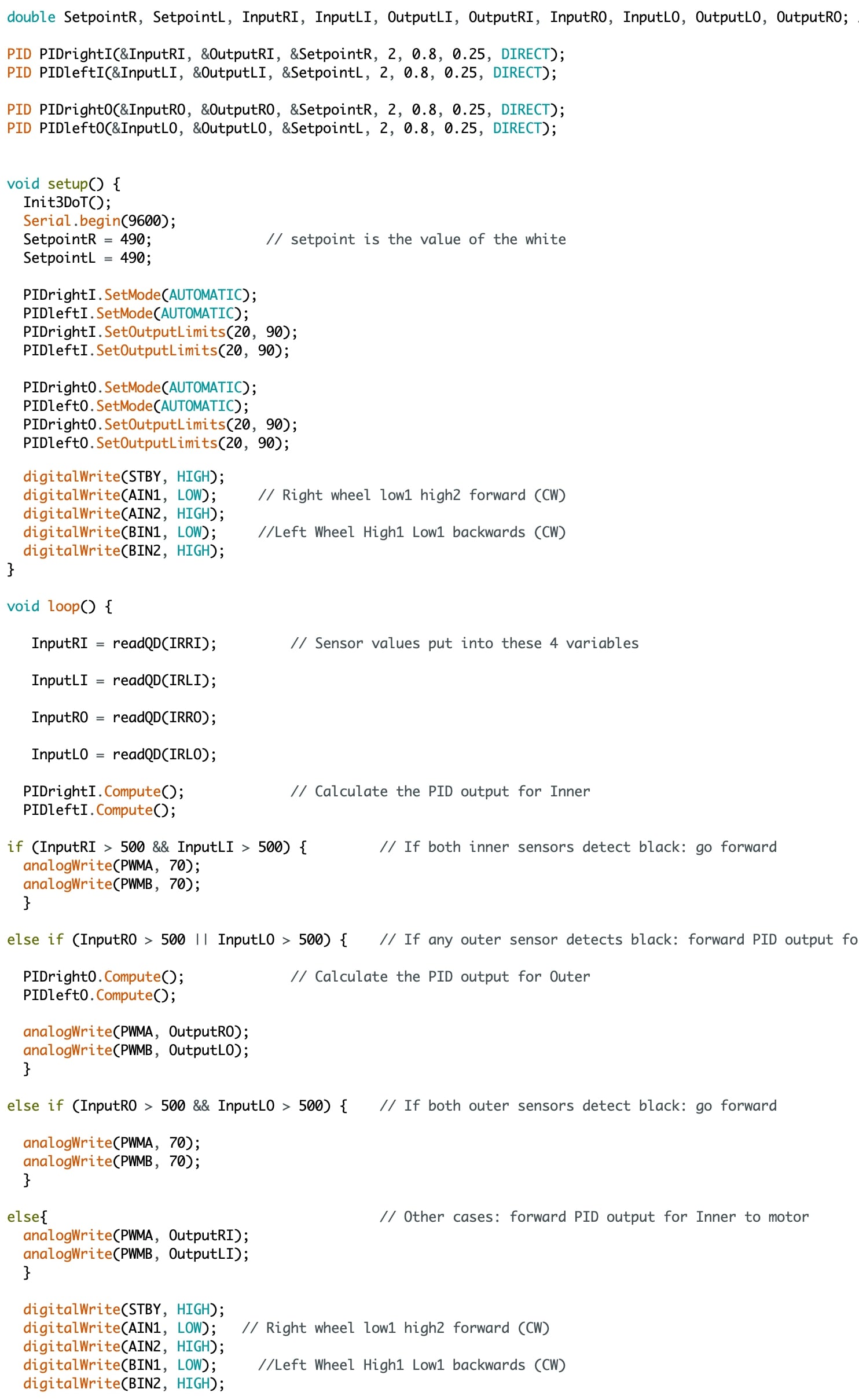
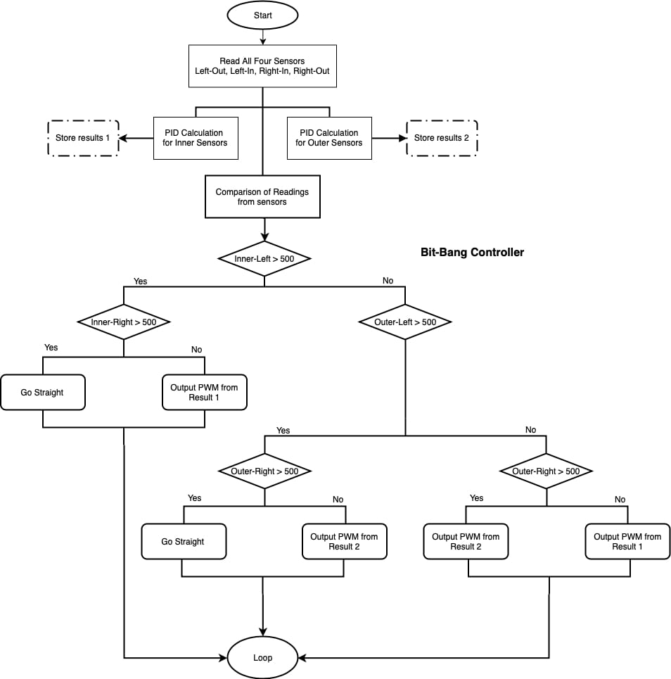
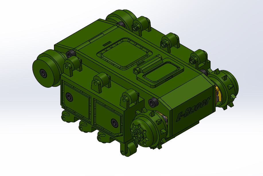
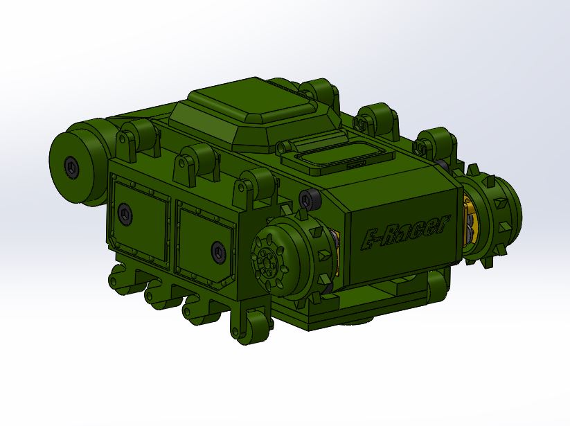
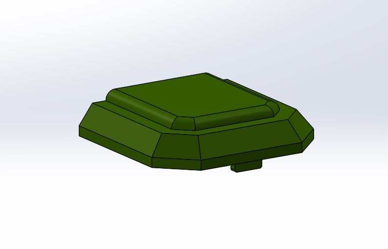
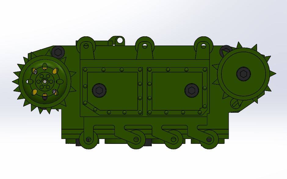

![Figure 1.1 Code for testing Sparkfun QRE1113 Analog Breakout Board [2]](https://www.arxterra.com/wp-content/uploads/2019/04/1.1.jpg)
![Figure 1.2 Code for testing Sparkfun QRE1113 Digital Breakout Board[2]](https://www.arxterra.com/wp-content/uploads/2019/04/1.2.png)