
The goal of this project was to improve on 302 Goliath tank design from the Fall 2016 Class and adapt to a completely different mission goal. The mission was to navigate a 2D paper/cloth maze under remote control and then have the Goliath repeat the route autonomously. For an added challenge an extra version was added that where all bots must navigate the maze autonomously without running into each other. As a backup option, the bots should be able to navigate a single path out of the maze.
Category: Goliath Generation #3
-

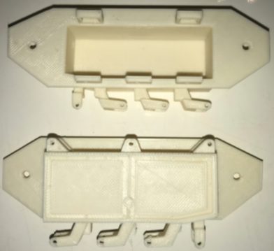
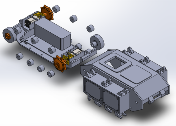
Goliath Fall 2017 – Final Print Model
Overall the design changes made to improve the ratio were successful, the execution was where I ran into the problems mentioned in a previous post [1]. The added cut outs for the LED display and the i/o port worked as expected. The IR sensor was not used in the mission. An improvement on that cut out can include flaring out the tunnel to avoid discrepancies in the readings. The color sensor cut outs were not used and the speaker holder was removed from the top panel.
-
Goliath Fall 2017 – Final Budget and Expenses
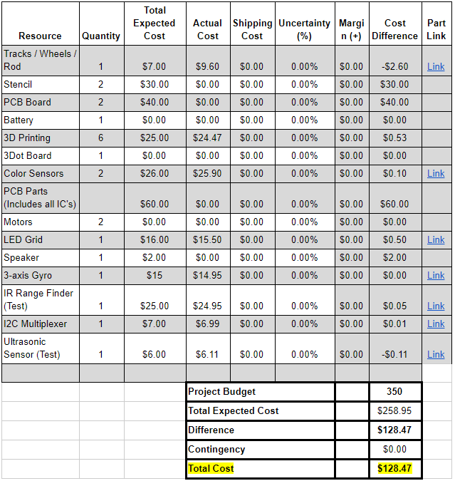
This post is in accordance with the project requirement L1.11, “Budget”. In comparison to both the total expected cost and actual cost column, we could see which resources were supplied, cut, or purchased.A good portion of the components was covered through the use of previous semesters’ components specifically the: motor, 3dot board, and battery. The project also conserved funds by cutting PCB development due to time constraints. Ultimately the Goliath was within the budget of $258.95 out of the $350 allocated budget having spent only $128.47. Most of these cost reduction came to not completing the PCB and having it assembled.
-
Goliath Fall 2017 – Design versus Printing Errors
[av_one_full first min_height=” vertical_alignment=” space=” custom_margin=” margin=’0px’ padding=’0px’ border=” border_color=” radius=’0px’ background_color=” src=” background_position=’top left’ background_repeat=’no-repeat’ animation=”]
[av_textblock size=’25’ font_color=” color=”]
Goliath Fall 2017
[/av_textblock][av_hr class=’invisible’ height=’-50′ shadow=’no-shadow’ position=’center’ custom_border=’av-border-thin’ custom_width=’50px’ custom_border_color=” custom_margin_top=’30px’ custom_margin_bottom=’30px’ icon_select=’yes’ custom_icon_color=” icon=’ue808′ font=’entypo-fontello’]
[av_textblock size=’25’ font_color=” color=”]
Design versus Printing Errors
[/av_textblock][av_textblock size=” font_color=’custom’ color=’#bfbfbf’]
Vanessa Enriquez (Manufacturing Engineer)
Approved by: Mark Huffman (Project Manager)
[/av_textblock][av_textblock size=” font_color=” color=”]
[/av_textblock]
[/av_one_full][av_one_full first min_height=” vertical_alignment=” space=” custom_margin=” margin=’0px’ padding=’0px’ border=” border_color=” radius=’0px’ background_color=” src=” background_position=’top left’ background_repeat=’no-repeat’ animation=”]
[av_heading tag=’h3′ padding=’10’ heading=’Introduction’ color=’custom-color-heading’ style=” custom_font=’#ff6a00′ size=” subheading_active=” subheading_size=’15’ custom_class=” admin_preview_bg=” av-desktop-hide=” av-medium-hide=” av-small-hide=” av-mini-hide=” av-medium-font-size-title=” av-small-font-size-title=” av-mini-font-size-title=” av-medium-font-size=” av-small-font-size=” av-mini-font-size=”][/av_heading][av_hr class=’invisible’ height=’-35′ shadow=’no-shadow’ position=’center’ custom_border=’av-border-thin’ custom_width=’50px’ custom_border_color=” custom_margin_top=’30px’ custom_margin_bottom=’30px’ icon_select=’yes’ custom_icon_color=” icon=’ue808′ font=’entypo-fontello’]
[av_textblock size=” font_color=’custom’ color=’#bfbfbf’]
Vanessa Enriquez (Manufacturing Engineer)
Approved by: Mark Huffman (Project Manager)
[/av_textblock][av_textblock size=” font_color=” color=” av-medium-font-size=” av-small-font-size=” av-mini-font-size=” admin_preview_bg=”]
The printing process was complicated because the difference between a design error and a printing error was noted fairly late in the process. The errors were identified on the more intricate panels, left and rights sides. The problems arose after the second print, at which point it was too late to make any substantial design changes prior to the final demonstration.
[/av_textblock]
[/av_one_full][av_one_full first min_height=” vertical_alignment=” space=” custom_margin=” margin=’0px’ padding=’0px’ border=” border_color=” radius=’0px’ background_color=” src=” background_position=’top left’ background_repeat=’no-repeat’ animation=”]
[av_heading heading=’Design Errors’ tag=’h3′ style=” size=” subheading_active=” subheading_size=’15’ padding=’10’ color=’custom-color-heading’ custom_font=’#ff6a00′][/av_heading][av_hr class=’invisible’ height=’-35′ shadow=’no-shadow’ position=’center’ custom_border=’av-border-thin’ custom_width=’50px’ custom_border_color=” custom_margin_top=’30px’ custom_margin_bottom=’30px’ icon_select=’yes’ custom_icon_color=” icon=’ue808′ font=’entypo-fontello’]
[av_textblock size=” font_color=’custom’ color=’#bfbfbf’]
Vanessa Enriquez (Manufacturing Engineer)
Approved by: Mark Huffman (Project Manager)
[/av_textblock][av_textblock size=” font_color=” color=”]
The design errors from the previous model F16 Goliath were not notable in the PLA printed F17 model [1]. For example, the section pictured below was only noticed in the ABS printed F17 final model.
[/av_textblock][av_image src=’/wp-content/uploads/2017/12/merror1-1.png’ attachment=’129564′ attachment_size=’full’ align=’center’ styling=” hover=” link=” target=” caption=” font_size=” appearance=” overlay_opacity=’0.4′ overlay_color=’#000000′ overlay_text_color=’#ffffff’ animation=’no-animation’][/av_image]
[av_textblock size=” font_color=” color=”]
Figure 1 – Weak support
[/av_textblock][av_textblock size=” font_color=” color=”]
The features were too thin, which caused the piece to break off during the cleaning process. The side panel was simply reprinted because it was assumed a printing error that could be fixed by adjusting the quality. This ultimately led to a waste of time and resources that could have been avoided by considering the thickness of each feature when designing.The orientation of the printed part also factored into the quality. This printing problem was dealt with by trial and error. The side panel was reprinted in the positions pictured below.
[/av_textblock][av_image src=’/wp-content/uploads/2017/12/merror2-4.png’ attachment=’129569′ attachment_size=’full’ align=’center’ styling=” hover=” link=” target=” caption=” font_size=” appearance=” overlay_opacity=’0.4′ overlay_color=’#000000′ overlay_text_color=’#ffffff’ animation=’no-animation’][/av_image]
[av_textblock size=” font_color=” color=”]
Figure 2 – Printing orientation
[/av_textblock][av_textblock size=” font_color=” color=”]
The first side panel in figure 4 resulted in the broken wheel support seen in figure 3. The second side panel fixed the weak support issue and had a well-defined tank design. Although, the latter resulted in warped hinges on the opposite side. The layout also affected the amount of support material used which resulted in the finishes shown below.
[/av_textblock][av_image src=’/wp-content/uploads/2017/12/merror3-2.png’ attachment=’129574′ attachment_size=’full’ align=’center’ styling=” hover=” link=” target=” caption=” font_size=” appearance=” overlay_opacity=’0.4′ overlay_color=’#000000′ overlay_text_color=’#ffffff’ animation=’no-animation’][/av_image]
[av_textblock size=” font_color=” color=”]
Figure 3 – Support material and finishes
[/av_textblock][av_textblock size=” font_color=” color=”]
The first and second panels correspond to the panels in figure 4. Notice the rough finish on the first panel due to the support material. In this example, both types of errors were present but the solution was in design. The hinges on the inside of the panel have to be removed and redesigned to avoid printing on a small surface area. This way the side can maintain the tank design.
[/av_textblock]
[/av_one_full][av_one_full first min_height=” vertical_alignment=” space=” custom_margin=” margin=’0px’ padding=’0px’ border=” border_color=” radius=’0px’ background_color=” src=” background_position=’top left’ background_repeat=’no-repeat’ animation=”]
[av_heading heading=’Printing Errors’ tag=’h3′ style=” size=” subheading_active=” subheading_size=’15’ padding=’10’ color=’custom-color-heading’ custom_font=’#ff6a00′][/av_heading][av_hr class=’invisible’ height=’-35′ shadow=’no-shadow’ position=’center’ custom_border=’av-border-thin’ custom_width=’50px’ custom_border_color=” custom_margin_top=’30px’ custom_margin_bottom=’30px’ icon_select=’yes’ custom_icon_color=” icon=’ue808′ font=’entypo-fontello’]
[av_textblock size=” font_color=’custom’ color=’#bfbfbf’]
Vanessa Enriquez (Manufacturing Engineer)
Approved by: Mark Huffman (Project Manager)
[/av_textblock][av_textblock size=” font_color=” color=”]
The change in printing material also added to the process. Compared to PLA, ABS proves to be stronger and has a cleaner finish when treated with acetone [2]. It also comes with a shrinking factor. Once the print cools off a popping sound indicates that the print has shrunk to its final dimension. For the first attempt of the ABS printed side panel, the print was scaled up to 101% to compensate. The cut outs did not line up well with the top and bottom panel that were also printed at 101%. After a couple measurements, the average percent error was calculated and the final print was scaled at 100.7%. This trial and error process showed the inconsistency of 3d printing that can be attributed to calibration or the settings chosen as well.
[/av_textblock]
[/av_one_full][av_one_full first min_height=” vertical_alignment=” space=” custom_margin=” margin=’0px’ padding=’0px’ border=” border_color=” radius=’0px’ background_color=” src=” background_position=’top left’ background_repeat=’no-repeat’ animation=”]
[av_heading tag=’h3′ padding=’10’ heading=’Suggestions’ color=’custom-color-heading’ style=” custom_font=’#ff6a00′ size=” subheading_active=” subheading_size=’15’ custom_class=” admin_preview_bg=” av-desktop-hide=” av-medium-hide=” av-small-hide=” av-mini-hide=” av-medium-font-size-title=” av-small-font-size-title=” av-mini-font-size-title=” av-medium-font-size=” av-small-font-size=” av-mini-font-size=”][/av_heading]
[av_hr class=’invisible’ height=’-35′ shadow=’no-shadow’ position=’center’ custom_border=’av-border-thin’ custom_width=’50px’ custom_border_color=” custom_margin_top=’30px’ custom_margin_bottom=’30px’ icon_select=’yes’ custom_icon_color=” icon=’ue808′ font=’entypo-fontello’]
[av_textblock size=” font_color=’custom’ color=’#bfbfbf’]
Vanessa Enriquez (Manufacturing Engineer)
Approved by: Mark Huffman (Project Manager)
[/av_textblock][av_textblock size=” font_color=” color=”]
Ideally in an efficient 3d print design the use of support material is minimal. Parts should be drawn with large surface area to avoid printing in air. The material used should be based on the customer requests as opposed to what is necessary to make the poor design function. Due to the lack of time, some of the errors mentioned were included in the final model. I suggest starting with the successful F16 model to resolve the minor design errors. In an effort to make the deadline, quick and poor design solutions were implemented in the final F17 chassis which will only complicate any further changes. The print time requirement was emphasized by the customer but by considering these aspects of 3d printing first, the time requirement will be fulfilled as a direct result. Every factor of printing (design, orientation, material, etc.) plays an important role in a quality print and understanding the difference between the two type of errors will simplify the process.
[/av_textblock][av_textblock size=” font_color=” color=” av-medium-font-size=” av-small-font-size=” av-mini-font-size=” admin_preview_bg=”]
Sources:- http://arxterra.com/goliath-fall-2017-post-pdr-adjustments-and-3d-prints/
- https://www.hubs.com/knowledge-base/pla-vs-abs-whats-difference/#strength
[/av_textblock]
[/av_one_full]
-

Goliath Fall 2017 – Goliath Arduino Code & Calibration
The purpose of this post is to link to the final Goliath code and explain the overall structure for future use. Secondly, to explain how the code needs to be updated and calibrated to a particular Goliath chassis. Overall, getting the Goliath code to work for this mission involved the creation of 16 files and over 1300 of lines of code. Most of the code is integrated with EE 444 and then layered with new content required to save and control the maze data. Combined the code takes 82% of the available memory space on the 3Dot board. Note: using the Goliath code involves modifying 2 files in the 3Dot library.
-

Goliath Fall 2017 – APP Directed RC (Record and Playback)
[av_one_full first min_height=” vertical_alignment=” space=” custom_margin=” margin=’0px’ padding=’0px’ border=” border_color=” radius=’0px’ background_color=” src=” background_position=’top left’ background_repeat=’no-repeat’ animation=”]
[av_textblock size=’25’ font_color=” color=”]
Goliath Fall 2017
[/av_textblock][av_hr class=’invisible’ height=’-50′ shadow=’no-shadow’ position=’center’ custom_border=’av-border-thin’ custom_width=’50px’ custom_border_color=” custom_margin_top=’30px’ custom_margin_bottom=’30px’ icon_select=’yes’ custom_icon_color=” icon=’ue808′ font=’entypo-fontello’]
[av_textblock size=’25’ font_color=” color=”]
APP Controlled RC (Record and Playback)
[/av_textblock][av_textblock size=” font_color=’custom’ color=’#bfbfbf’]
Mark Huffman (Project Manager)
[/av_textblock][av_textblock size=” font_color=” color=”]
[/av_textblock]
[/av_one_full][av_one_full first min_height=” vertical_alignment=” space=” custom_margin=” margin=’0px’ padding=’0px’ border=” border_color=” radius=’0px’ background_color=” src=” background_position=’top left’ background_repeat=’no-repeat’ animation=”]
[av_heading tag=’h3′ padding=’10’ heading=’Introduction’ color=’custom-color-heading’ style=” custom_font=’#ff6a00′ size=” subheading_active=” subheading_size=’15’ custom_class=” admin_preview_bg=” av-desktop-hide=” av-medium-hide=” av-small-hide=” av-mini-hide=” av-medium-font-size-title=” av-small-font-size-title=” av-mini-font-size-title=” av-medium-font-size=” av-small-font-size=” av-mini-font-size=”][/av_heading][av_hr class=’invisible’ height=’-35′ shadow=’no-shadow’ position=’center’ custom_border=’av-border-thin’ custom_width=’50px’ custom_border_color=” custom_margin_top=’30px’ custom_margin_bottom=’30px’ icon_select=’yes’ custom_icon_color=” icon=’ue808′ font=’entypo-fontello’]
[av_textblock size=” font_color=’custom’ color=’#bfbfbf’]
By Mark Huffman (Project Manager)
[/av_textblock][av_textblock size=” font_color=” color=” av-medium-font-size=” av-small-font-size=” av-mini-font-size=” admin_preview_bg=”]
This guide aims to explain configuring Arxterra for custom commands needed for RC control, then the steps to interpret these received commands. Lastly using this received information to control Goliath through the maze either by recording a route to EEPROM or playing back a saved route.
[/av_textblock]
[/av_one_full][av_one_full first min_height=” vertical_alignment=” space=” custom_margin=” margin=’0px’ padding=’0px’ border=” border_color=” radius=’0px’ background_color=” src=” background_position=’top left’ background_repeat=’no-repeat’ animation=”]
[av_heading tag=’h3′ padding=’10’ heading=’Arxterra Custom Commands’ color=’custom-color-heading’ style=” custom_font=’#ff6a00′ size=” subheading_active=” subheading_size=’15’ custom_class=”][/av_heading][av_hr class=’invisible’ height=’-35′ shadow=’no-shadow’ position=’center’ custom_border=’av-border-thin’ custom_width=’50px’ custom_border_color=” custom_margin_top=’30px’ custom_margin_bottom=’30px’ icon_select=’yes’ custom_icon_color=” icon=’ue808′ font=’entypo-fontello’]
[av_textblock size=” font_color=’custom’ color=’#bfbfbf’]
By Mark Huffman (Project Manager)
[/av_textblock][av_textblock size=” font_color=” color=”]
To set up the app for remote control an excerpt of the Goliath Setup and control guide is repeated here.After obtaining access to either the Android or IOS Arxterra App, we need to set up at least two actions. We need a selection menu for changing the operating mode of Goliath and we need to set the interface for d-pad motor control.
Step 1: To get to Custom Commands and Telemetry, enable developer mode and then enter the interface in the Arxterra App.
[/av_textblock][av_image src=’/wp-content/uploads/2017/12/pic1-1-169×300.png’ attachment=’125328′ attachment_size=’medium’ align=’center’ styling=” hover=” link=’lightbox’ target=” caption=” font_size=” appearance=” overlay_opacity=’0.4′ overlay_color=’#000000′ overlay_text_color=’#ffffff’ animation=’no-animation’][/av_image]
[av_image src=’/wp-content/uploads/2017/12/pic2-1-169×300.png’ attachment=’125329′ attachment_size=’medium’ align=’center’ styling=” hover=” link=’lightbox’ target=” caption=” font_size=” appearance=” overlay_opacity=’0.4′ overlay_color=’#000000′ overlay_text_color=’#ffffff’ animation=’no-animation’][/av_image]
[av_textblock size=” font_color=” color=”]
Step 2: Add a “Select” Entity in order to add a selection menu for changing the operating mode.
[/av_textblock][av_image src=’/wp-content/uploads/2017/12/addcommand-1-300×266.png’ attachment=’125331′ attachment_size=’medium’ align=’center’ styling=” hover=” link=’lightbox’ target=” caption=” font_size=” appearance=” overlay_opacity=’0.4′ overlay_color=’#000000′ overlay_text_color=’#ffffff’ animation=’no-animation’][/av_image]
[av_textblock size=” font_color=” color=”]
Step 3: Click on the added Entity. In the lower menu make sure to add at least these three options. These will determine the modes you can switch into.(0) Predetermined Route Mode
(1) Record Route Mode
(2) Playback Route Mode
[/av_textblock][av_image src=’/wp-content/uploads/2017/12/pic5-169×300.png’ attachment=’125335′ attachment_size=’medium’ align=’center’ styling=” hover=” link=’lightbox’ target=” caption=” font_size=” appearance=” overlay_opacity=’0.4′ overlay_color=’#000000′ overlay_text_color=’#ffffff’ animation=’no-animation’][/av_image]
[av_textblock size=” font_color=” color=”]
Step 4: Click on on the marker to edit the details of the “Selection Entity”. Most importantly take note of the entity ID this will be the reference for receiving the command.
[/av_textblock][av_image src=’/wp-content/uploads/2017/12/pic4-2-169×300.png’ attachment=’125345′ attachment_size=’medium’ align=’center’ styling=” hover=” link=’lightbox’ target=” caption=” font_size=” appearance=” overlay_opacity=’0.4′ overlay_color=’#000000′ overlay_text_color=’#ffffff’ animation=’no-animation’][/av_image]
[av_textblock size=” font_color=” color=”]
Step 5: Press “done” and return to the main control screen. If there are two sliders on the bottom of the screen instead of a d-pad do this:
[/av_textblock][av_image src=’/wp-content/uploads/2017/12/joystick-169×300.jpg’ attachment=’125357′ attachment_size=’medium’ align=’center’ styling=” hover=” link=’lightbox’ target=” caption=” font_size=” appearance=” overlay_opacity=’0.4′ overlay_color=’#000000′ overlay_text_color=’#ffffff’ animation=’no-animation’][/av_image]
[av_textblock size=” font_color=” color=”]
Now the app is all set up to send commands to the 3Dot.
[/av_textblock][av_textblock size=” font_color=’custom’ color=’#ff6a00′]
Source Material- http://arxterra.com/goliath-fall-2017-app-setup-and-remote-control-user-guide/
- http://arxterra.com/news-and-eventsmembers3dot-robots3dot-goliatharxterra-3dot-training-telerobotic-mode/
- https://www.arxterra.com/training-on-arxterra-3dot-app-rc-mode/
[/av_textblock]
[/av_one_full][av_one_full first min_height=” vertical_alignment=” space=” custom_margin=” margin=’0px’ padding=’0px’ border=” border_color=” radius=’0px’ background_color=” src=” background_position=’top left’ background_repeat=’no-repeat’ animation=”]
[av_heading tag=’h3′ padding=’10’ heading=’3Dot Custom Command Setup’ color=’custom-color-heading’ style=” custom_font=’#ff6a00′ size=” subheading_active=” subheading_size=’15’ custom_class=” admin_preview_bg=” av-desktop-hide=” av-medium-hide=” av-small-hide=” av-mini-hide=” av-medium-font-size-title=” av-small-font-size-title=” av-mini-font-size-title=” av-medium-font-size=” av-small-font-size=” av-mini-font-size=”][/av_heading]
[av_hr class=’invisible’ height=’-35′ shadow=’no-shadow’ position=’center’ custom_border=’av-border-thin’ custom_width=’50px’ custom_border_color=” custom_margin_top=’30px’ custom_margin_bottom=’30px’ icon_select=’yes’ custom_icon_color=” icon=’ue808′ font=’entypo-fontello’]
[av_textblock size=” font_color=’custom’ color=’#bfbfbf’]
By Mark Huffman (Project Manager)
[/av_textblock][av_textblock size=” font_color=” color=”]
Using a combined function of other guides and the reference example included in the 3Dot library, setting up receiving custom commands in Arduino is simple. Basically, define command addresses (Entity ID’s for earlier), set up calling in the 3Dot library by using onCommand(), then simply write the received functions that will be called. The focus here is only setting up commands for changing the operation mode from the Select Entity define above and overwriting the move command for deciding at intersections.
[/av_textblock][av_textblock size=” font_color=” color=”]
Step 1: Add a definition for the “mode selection Entity” address#define MODE 0x40
[/av_textblock][av_textblock size=” font_color=” color=”]
Step 2: Setup handlers for onCommand Function. These names are the functions that will be called when that particular Entity address is called.void moveHandler (uint8_t cmd, uint8_t param[], uint8_t n);
void modeHandler (uint8_t cmd, uint8_t param[], uint8_t n);
const uint8_t CMD_LIST_SIZE = 2; // total number of custom commands
[/av_textblock][av_textblock size=” font_color=” color=”]
Step 3: Setup the onCommand Function, this links the void with the actual Entity address desired. Note: MOVE is provided by the library and is already defined to the proper address.Robot3DoTBoard::cmdFunc_t onCommand[CMD_LIST_SIZE] = {{MODE, modeHandler}, {MOVE, moveHandler}};
[/av_textblock][av_textblock size=” font_color=” color=” av-medium-font-size=” av-small-font-size=” av-mini-font-size=” admin_preview_bg=”]
Step 4: Setup the internal onCommand Function within the 3Dot Library. This should be placed just afterRobot3DoT.begin();insetup();Robot3DoT.setOnCommand(onCommand, CMD_LIST_SIZE);
[/av_textblock][av_textblock size=” font_color=” color=” av-medium-font-size=” av-small-font-size=” av-mini-font-size=” admin_preview_bg=”]
Step 5: Add the functions defined. Note: these functions are designed to work with the current Goliath code layout, however, the general point still stands.MoveHandler (Overwrites the general move command)
Methodology:
1 – Check if at an intersection waiting for a command.
2- Break out move command to its parts to indicate the turn direction
Received param format: ##(Left Motor Direction) ##(Left Motor Speed) ##(Right Motor Direction) ##(Right Motor Speed)
Only look at motor directions
if 0x01(Left) && 0x01(Right) = Foward
if 0x02(Left) && 0x02(Right) = Backward
if 0x01(Left) && 0x02(Right) = Turn Right
if 0x02(Left) && 0x01(Right) = Turn Left
3- Set turn direction as indicated to be used later for actual turing
void moveHandler(uint8_t cmd, uint8_t param[], uint8_t n)

{

// Set the turn direction and record it, (ONLY ACCEPT AT INTERSECTIONS)

if(physicalBot.turnCommand == 4){ // at intersection for turn command

// 01 2B 01 2B == Foward

if (param[0] == 0x01 && param[2] == 0x01){

Serial.println("Go Straight");

physicalBot.turnCommand = 0;

// 02 2B 02 2B == Backward

}else if(param[0] == 0x02 && param[2] == 0x02){

Serial.println("Go Backward");

physicalBot.turnCommand = 3;

// 01 00 02 00 == Right

}else if(param[0] == 0x01 && param[2] == 0x02){

Serial.println("Go Right");

physicalBot.turnCommand = 1;

// 02 00 01 00 == Left

}else if(param[0] == 0x02 && param[2] == 0x01){

Serial.println("Go Left");

physicalBot.turnCommand = 2;

}

}

}
ModeHandler (Used to change operating mode)
Methodology:
1 – Look at the received param value (a number between 0-2) to determine the new mode
2- Reset all internal variables (Maze position, heading, current route index and reset to the start maze position)
3- Change the mode variable to the new setting
void modeHandler(uint8_t cmd, uint8_t param[], uint8_t n)

{

//Changes the set mode

// Mode 0 = Predetermined Route

// Mode 1 = Record Mode

// Mode 2 = Playback Mode

if(param[0] == 0 && physicalBot.mode != 0){ //Predetermined Route

// change mode and reset needed paramters

physicalBot.mode = 0;

resetPhysicalBot();

}

if(param[0] == 1 && physicalBot.mode != 1){ //Record Mode

// change mode and reset needed paramters

physicalBot.mode = 1;

resetPhysicalBot();

}

if(param[0] == 2 && physicalBot.mode != 2){ //Playback Mode

// change mode and reset needed paramters

physicalBot.mode = 2;

resetPhysicalBot();

}

}
[/av_textblock][av_textblock size=” font_color=” color=”]
Side note: All custom commands can only be processed and received by Robot3Dot.loop(); when contained within the main loop() call. Meaning that any code must not “while” loop outside of the main loop if a custom command is needed. So, a state machine used within loop() is the recommended approach.
[/av_textblock][av_textblock size=” font_color=’custom’ color=’#ff6a00′]
Source Material- http://web.csulb.edu/~hill/ee400d/Technical%20Training%20Series/3DoT/3DoT%20Training%20Documentation.pdf
- http://arxterra.com/with-command-move-override-for-maze-navigation/
[/av_textblock]
[/av_one_full][av_one_full first min_height=” vertical_alignment=” space=” custom_margin=” margin=’0px’ padding=’0px’ border=” border_color=” radius=’0px’ background_color=” src=” background_position=’top left’ background_repeat=’no-repeat’ animation=”]
[av_heading tag=’h3′ padding=’10’ heading=’Modifying Whichway for Recording and Playback’ color=’custom-color-heading’ style=” custom_font=’#ff6a00′ size=” subheading_active=” subheading_size=’15’ custom_class=”][/av_heading][av_hr class=’invisible’ height=’-35′ shadow=’no-shadow’ position=’center’ custom_border=’av-border-thin’ custom_width=’50px’ custom_border_color=” custom_margin_top=’30px’ custom_margin_bottom=’30px’ icon_select=’yes’ custom_icon_color=” icon=’ue808′ font=’entypo-fontello’]
[av_textblock size=” font_color=’custom’ color=’#bfbfbf’]
By Mark Huffman (Project Manager)
[/av_textblock][av_textblock size=” font_color=” color=”]
Recording the route using the method whichway (Using the software Translation), takes only a simple modification. Then a set of support code to translate the received direction command. Playback mode is the easiest to implement as long as EEPROM writing and reading has been implemented. Note: The code represented is for Goliath, however the method and idea still holds true.
[/av_textblock][av_heading tag=’h4′ padding=’10’ heading=’Whichway – Methodology’ color=’custom-color-heading’ style=” custom_font=’#ff6a00′ size=” subheading_active=” subheading_size=’15’ custom_class=”][/av_heading]
[av_hr class=’invisible’ height=’-35′ shadow=’no-shadow’ position=’center’ custom_border=’av-border-thin’ custom_width=’50px’ custom_border_color=” custom_margin_top=’30px’ custom_margin_bottom=’30px’ icon_select=’yes’ custom_icon_color=” icon=’ue808′ font=’entypo-fontello’]
[av_textblock size=” font_color=’custom’ color=’#bfbfbf’]
By Mark Huffman (Project Manager)
[/av_textblock][av_textblock size=” font_color=” color=”]
Record Mode Methodology:1- Any intersection that does not require a decision (Hallway, left turn, right turn or a dead end) complete the action automatically.
2- If at an intersection with three or more open paths, look at the operating mode (in record mode).
3- Stop the bot, and set a flag to wait for a new direction to be received.
4- When a new direction is received (by the custom command), check that it is a valid direction (An open path not a wall).
5- If it is, save the turn direction to EEPROM and then increment the route index.
6- Then start the bot again and turn in the indicated direction.
Playback Mode Methodology:
1- Any intersection that does not require a decision (Hallway, left turn, right turn or a dead end) complete the action automatically.
2- If at an intersection with three or more open paths, look at the operating mode (in playback mode).
3- Using the current route index, read the next turn direction from EEPROM and then increment the route index.
4- Move the bot again and turn in the indicated direction.
[/av_textblock]
[av_heading tag=’h4′ padding=’10’ heading=’Whichway – Goliath Implementation’ color=’custom-color-heading’ style=” custom_font=’#ff6a00′ size=” subheading_active=” subheading_size=’15’ custom_class=”][/av_heading]
[av_hr class=’invisible’ height=’-35′ shadow=’no-shadow’ position=’center’ custom_border=’av-border-thin’ custom_width=’50px’ custom_border_color=” custom_margin_top=’30px’ custom_margin_bottom=’30px’ icon_select=’yes’ custom_icon_color=” icon=’ue808′ font=’entypo-fontello’]
[av_textblock size=” font_color=” color=”]
uint8_t whichWay(MyRobot mazeBot){

switch(roomType(mazeBot)){

case 0:

// 4 way Intersection

if(physicalBot.mode == 1){

LEDDirection("?");

robotMovement("Stop");

physicalBot.turnCommand = 4;

physicalBot.turnWait = true;

physicalBot.wallDir = 0;

return 0x05;

}else if(physicalBot.mode == 2){

physicalBot.routeIndex++;

return EEPROM_read(physicalBot.routeIndex);

}

return 0x00;

case 1:

// T-Intersection (Wall to right)

if(physicalBot.mode == 0){

physicalBot.routeN++;

if(physicalBot.routeN == 3) // Predetermined ROUTE

return 0x02;

}else if(physicalBot.mode == 1){

LEDDirection("?");

robotMovement("Stop");

physicalBot.turnCommand = 4;

physicalBot.turnWait = true;

physicalBot.wallDir = 1;

return 0x05;

}else if(physicalBot.mode == 2){

physicalBot.routeIndex++;

return EEPROM_read(physicalBot.routeIndex);

}

return 0x00;

case 2:

// T-Intersection (Wall to Left)

if(physicalBot.mode == 0){

physicalBot.routeI++;

if(physicalBot.routeI == 1 || physicalBot.routeI == 2) // Predetermined ROUTE

return 0x01;

}else if(physicalBot.mode == 1){

LEDDirection("?");

robotMovement("Stop");

physicalBot.wallDir = 2;

physicalBot.turnCommand = 4;

physicalBot.turnWait = true;

return 0x05;

}else if(physicalBot.mode == 2){

physicalBot.routeIndex++;

return EEPROM_read(physicalBot.routeIndex);

}

return 0x00;

case 3:

// Hallway Continue Foward

return 0x00;

case 4:

// T-Intersection (Wall in Front)

if(physicalBot.mode == 0){

return 0x02;

}else if(physicalBot.mode == 1){

LEDDirection("?");

robotMovement("Stop");

physicalBot.turnCommand = 4;

physicalBot.turnWait = true;

physicalBot.wallDir = 4;

return 0x05;

}else if(physicalBot.mode == 2){

physicalBot.routeIndex++;

return EEPROM_read(physicalBot.routeIndex);

}

return 0x01;

case 5:

// Left Turn (Turn Left)

//setTurn("Left");

return 0x02; // Predetermined ROUTE

case 6:

// Right Turn (Turn Right)

//setTurn("Right");

return 0x01;

case 7:

// Dead End (Turn Around)

//setTurn("Around");

return 0x03;

}

}
[/av_textblock][av_textblock size=” font_color=” color=”]
Goliath support code for interpreting decision direction. Located within loop()
[/av_textblock][av_textblock size=” font_color=” color=”]
if (physicalBot.turnWait == true && physicalBot.turnCommand != 4) {

uint8_t newTurn = 4; // physicalBot.turnCommand != 4 when a custom Move command has been recived

switch (physicalBot.wallDir) { // check that the new direction is valid for completing a turn (Not going to turn into a wall)

case 0: // 4 way Intersection

newTurn = physicalBot.turnCommand;

break;

case 1: // T-Intersection (Wall to right)

if (physicalBot.turnCommand == 1)

newTurn = 4;

else

newTurn = physicalBot.turnCommand;

break;

case 2: // T-Intersection (Wall to Left)

if (physicalBot.turnCommand == 2)

newTurn = 4;

else

newTurn = physicalBot.turnCommand;

break;

case 4: // T-Intersection (Wall in Front)

if (physicalBot.turnCommand == 0)

newTurn = 4;

else

newTurn = physicalBot.turnCommand;

break;

}

if (newTurn != 4) { // Only true if the new turn direction was a valid choice

robotMovement("Go"); // start movement again

robotMovement("Foward"); // start movement again

physicalBot.turnWait = false; // start movement again

mazeBot.turn = newTurn; // Set the turn direction

physicalBot.routeIndex++; // update the route index

EEPROM_write(physicalBot.routeIndex, mazeBot.turn); // Save the new direction to EEPROM
[/av_textblock][av_textblock size=” font_color=” color=”]
if (mazeBot.turn == 0x01) {

physicalBot.turnAct = "Right";

LEDDirection(physicalBot.turnAct);

physicalBot.turnTime = millis() + 1300;

} else if (mazeBot.turn == 0x02) {

physicalBot.turnAct = "Left";

LEDDirection(physicalBot.turnAct);

physicalBot.turnTime = millis() + 1300;

} else if (mazeBot.turn == 0x03) {

physicalBot.turnAct = "Around";

LEDDirection(physicalBot.turnAct);

physicalBot.turnTime = millis() + 1300;

} else if (mazeBot.turn == 0x00) {

LEDDirection("Foward");

}

} else {

physicalBot.turnCommand = 4; // If direction was not valid, reset and wait for another recieved custom command

}

}
[/av_textblock][av_textblock size=” font_color=” color=”]
Note: “physicalBot” refers to a structure used to keep all variables involved with physical movement together. “LEDDirection” is used only to display visuals on the LED display on Goliath.
[/av_textblock][av_textblock size=” font_color=’custom’ color=’#ff6a00′]
Source Material- http://arxterra.com/ee346ee444-software-translation-to-ee400d/
- http://arxterra.com/read-from-eeprom/
- http://arxterra.com/write-to-eeprom/
[/av_textblock]
[/av_one_full] -
Goliath Fall 2017 – Gyro and LED Custom PCB
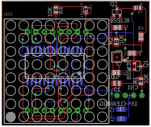
The custom printed circuit board was designed to include both the gyro sensor and the LED display on the top panel. The LED will display the direction the tank is taking within the maze. By working with my project and division manager the schematic and layout were created on Eagle CAD. The files were not submitted in a timely manner to ensure the level 1 requirement that states the Goliath shall be ready by December 13th. The following schematic and layout were submitted on December 1st.
-

Goliath Fall 2017 – APP Setup and Remote Control User Guide
The goal of this guide is to provide setup for the custom commands needed on the Arxterra APP side in order to control the Goliath running the final code. Secondly, this guide will provide instructions on how to control the goliath correctly from the commands defined.
-
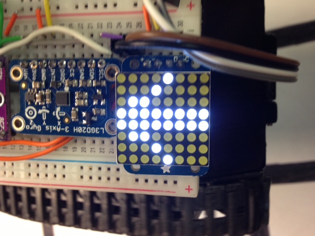
Goliath Fall 2017 – LED Grid Display
Based on our L1 requirements to have a LED display and the L2 sub-requirements to indicate the next turn direction, having an LED grid display was a stretch goal. After some (what turned out to be pretty simple work) the LED proves very useful in indicating to the user the intended direction when user input is needed. Also, it is used to indicate when an object is detected.
The LED 8×8 display we picked is easily controlled by HT16K33 display driver, which makes making shapes and patterns simple. Plus, it uses the I2C interface keeping the connections from the microcontroller low considering that 64 individual LED’s are being controlled.
-
Goliath Fall 2017 – Post PDR Adjustments and 3D prints
After taking a closer look at the IR sensor, I realized that the sensor needed to be relocated to avoid contact with the first motor. The distance between the top panel and the front motor is not large enough to fit the sensor. Although we did consider redesigning the top, the tank will lose its overall ‘tank-like’ structure and the scaled dimensions would be skewed.
The top panel IR cut-out was relocated to the front of the bottom panel. The bottom panel was redesigned to fit the sensor between the first motor and the 3 dot board. I was able to create an IR sensor part to assemble along with the 3-dot board. The compact layout prevents the lengthening of the tank. Screw hinges were also added to the bottom panel to secure the side panels. Lastly, tank details were added to the side panels that were previously blank during PDR. The figure below shows the current layout for the components within the tank.