Category: Goliath Generation #3

  • Goliath Fall 2017 – Requirements Update

    Goliath Fall 2017 – Requirements Update

    1. Project Schedule – Project shall be ready by Wednesday, December 13th, 2017

    2. Operational Task – The Goliath will have the functionality to be connected remotely using Arxterra

    3. Toy – Elements – The Goliath will behave like a toy

    4. Driving Surface – The Goliath will be able to drive on flat surfaces

    5. Driving Surface – The Goliath shall traverse on cloth, paper and linoleum

    6. Print Time – All modifications shall allow the Goliath to be printed under a total print time of 6 hours with no part taking longer than 2 hours

  • Goliath Fall 2017 – Robot Detection

    Goliath Fall 2017 – Robot Detection

    Detection is a subroutine used in the collusion protocol. The subfunction will employ an IR proximity sensor, VL6180. The distance outputted  will be converted to a discrete value called squares which are dependent on the measured squares from the physical maze. Each side of the square is roughly 6.6 cms long meaning we have a required range of 1 square. With accordance with the rules of the maze. Ultimately the subroutine will output or return a boolean value which indicates whether or not an object is within the expected range.

  • Goliath Fall 2017 – Mock-up Motor Test

    Goliath Fall 2017 – Mock-up Motor Test

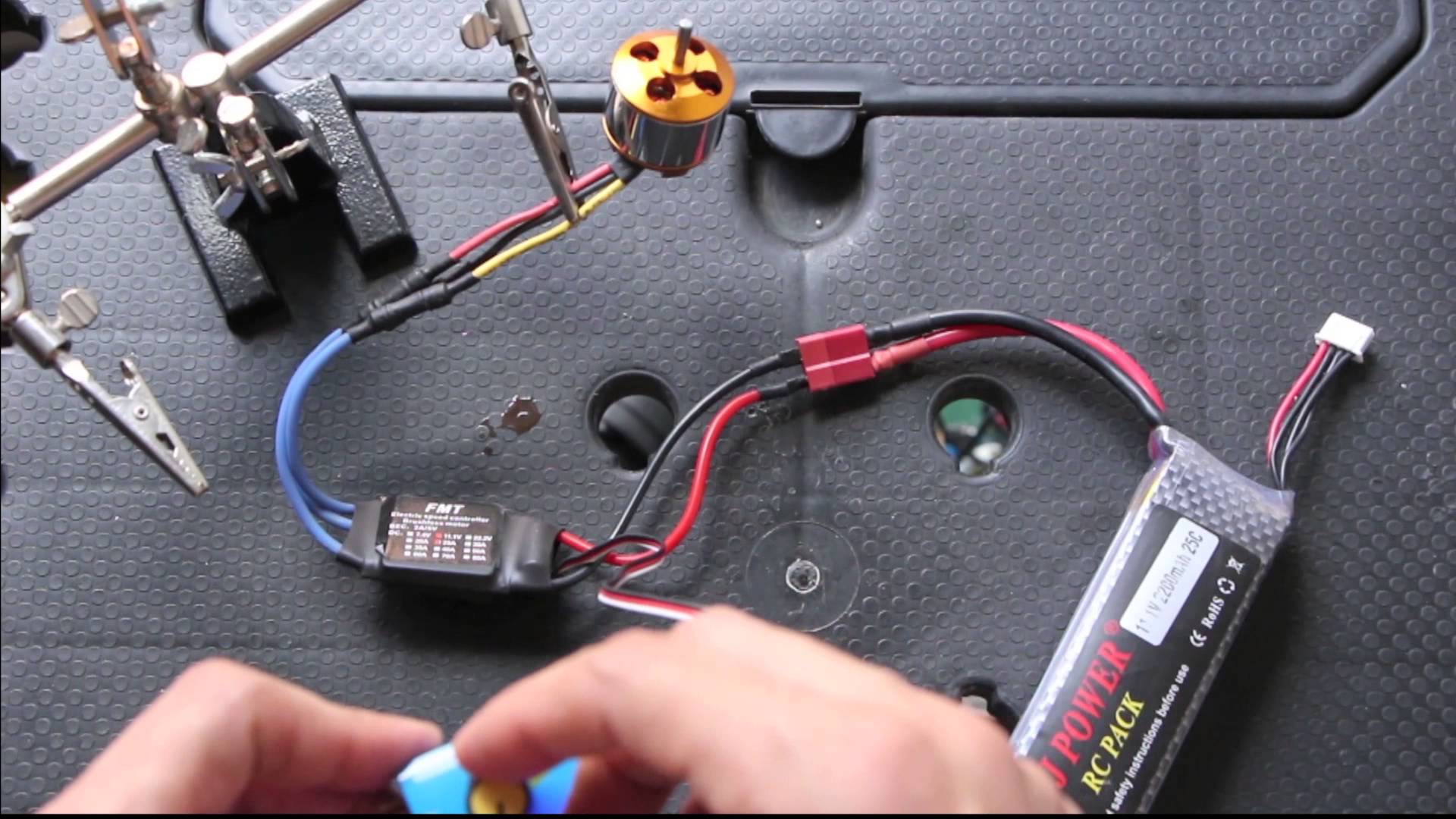
    The purpose of this post is to relay and archive  the results the Mock-up Motor specific testing. The measured results are the speed and the current draw. The Goliath will use 2 micro motor gear. It is also subject to a weight load of about 190 grams. This experiment was tested on a carpet surface.

  • Goliath Fall 2017 – 3DOT 4.54

    Goliath Fall 2017 – 3DOT 4.54

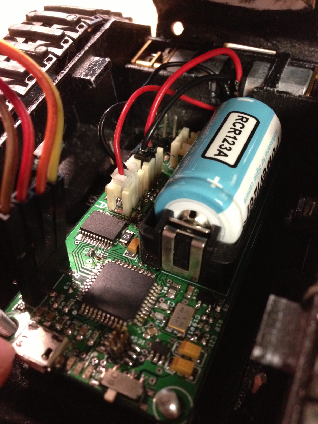
    While waiting for the new 3Dot board (5.03) the 3Dot 4.54 version board is being used for development. Physically the boards are nearly the same. The only major change that affects us is the placement of headers and connectors. On the new board, there are two separate locations to connect I2C devices. So, our devices can route to which is more convenient.

    Our current plan is to design everything with the now working 4.54 but, keep in mind and be compatible with the new 5.03 board. Currently, all software tests, breadboarding and testing have been conducted on the 4.54. The goal is the new board will just be plug and play.

  • Goliath Fall 2017 – Breadboarding

    Goliath Fall 2017 – Breadboarding

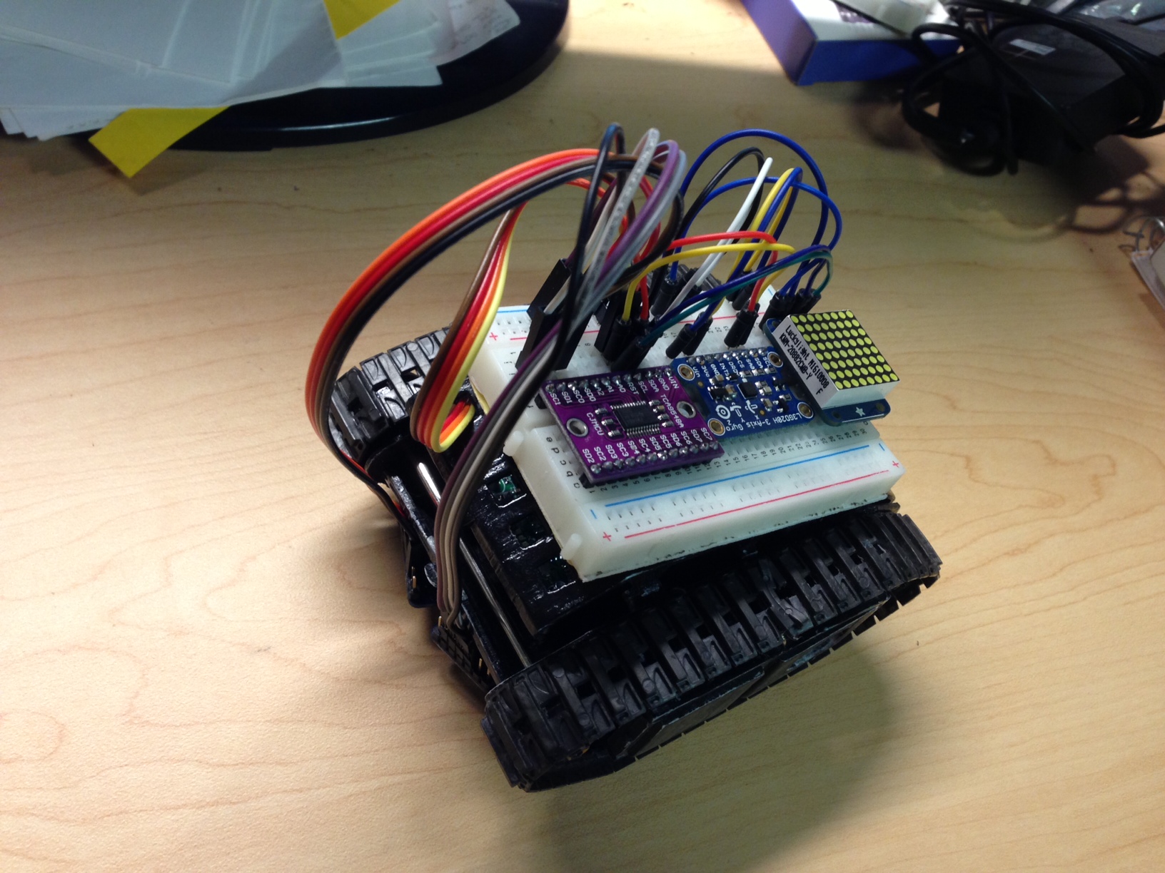
    All major components have been laid out on a breadboard for testing the majority of the program work. Most importantly being the color sensors and gyro. As both provide vital functions for navigating the maze. This breadboarding has provided very useful as the previous Goliath has been used as a test platform with room for new components on top. All major programming work can be completed or at the very least defined while the final body work is completed.

    The items connected up include:

    LED Grid Display – Connected to I2C

    Color Sensors – Connected to the I2C multiplexer (0 and 1)

    Gyro Sensor – Connected to I2C

    The only sensor missing at this time is the IR proximity sensor. But, it could be easily extended off the breadboard.

  • Goliath Fall 2017 – Gyro Test & Power Usage

    Goliath Fall 2017 – Gyro Test & Power Usage

    The measured results are at the board level of the required voltage and current draw of the Gyro sensor. The voltage was able to measure with a simple multimeter but the current draw was in the single digit milliamps requiring us to use a more precise multimeter. We supplementally added a demo of how the gyro functions.

  • Goliath Fall 2017 – Recommended Custom Telemetry & Custom Commands

    Goliath Fall 2017 – Recommended Custom Telemetry & Custom Commands

    The purpose of this document is to define telemetry visuals and custom commands required in Arxterra to control the Goliath during the mission. These definitions will be used in the software design on both the application side and the internal operating code of the Goliath. These commands may be subject to change if some are not possible to achieve or new ones are discovered.

  • Goliath Fall 2017 – Color Sensor Line Following

    Goliath Fall 2017 – Color Sensor Line Following

    The theory behind line following with color sensors is the same reasoning used when using IR sensors. A sensor is placed on each side of the centerline and both sensors are constantly read back to adjust heading direction as based on which sensor is detecting.

    Both Sensors White: On-the-line, continue forward straight line.

    Right Sensor Black: Off-the-line, veer to the right.

    Left Sensor Black: Off-the-line, veer to the left.

    Both Sensors Black: On an intersection, detect it then continue straight.

    To keep things looking smooth a really simple PID element was added. When correcting for a turn the motor speed is first influenced gradually based on continuous time of the error. This method is very basic and can be built upon to build an even more graceful correction algorithm.

  • Goliath Fall 2017 – Initial Design

    Goliath Fall 2017 – Initial Design

    After inspecting last year’s final product, I began to redesign the dimensions of the overall body of the tank. While reviewing their SolidWorks’ files, I calculated a maximum possible decrease in width of 8.95 mm. The following changes were made in order to minimize the overall width of the tank and other changes were to satisfy the requirements that were derived in our preliminary plan.

  • Goliath Fall 2017 – Component Testing

    Goliath Fall 2017 – Component Testing

    This project will be including 4 new peripherals and parts for this iteration of the Goliath. To fulfil the following requirements:

    Operation Task – Autonomous, L1(13)

    Operation Task – Recall, L1(14)

    These parts will be added eventually to the PCB design on the Goliath. The tested components so far are as follows: Color Sensors, LED Matrix, Range Finder.