[av_one_full first min_height=” vertical_alignment=” space=” custom_margin=” margin=’0px’ padding=’0px’ border=” border_color=” radius=’0px’ background_color=” src=” background_position=’top left’ background_repeat=’no-repeat’ animation=”]
[av_textblock size=’35’ font_color=” color=” av-medium-font-size=” av-small-font-size=” av-mini-font-size=” admin_preview_bg=”]
IloMilo
Summary Blog Post
[/av_textblock]
[av_hr class=’default’ height=’50’ shadow=’no-shadow’ position=’center’ custom_border=’av-border-thin’ custom_width=’50px’ custom_border_color=” custom_margin_top=’30px’ custom_margin_bottom=’30px’ icon_select=’yes’ custom_icon_color=” icon=’ue808′ font=’entypo-fontello’ admin_preview_bg=”]
[av_textblock size=” font_color=’custom’ color=’#bfbfbf’ av-medium-font-size=” av-small-font-size=” av-mini-font-size=” admin_preview_bg=”]
Author/s: Toby Johnson, Jessica Benitez, Farland Nguyen
[/av_textblock]
[av_hr class=’short’ height=’50’ shadow=’no-shadow’ position=’left’ custom_border=’av-border-thin’ custom_width=’50px’ custom_border_color=” custom_margin_top=’30px’ custom_margin_bottom=’30px’ icon_select=’yes’ custom_icon_color=” icon=’ue808′ font=’entypo-fontello’ admin_preview_bg=”]
[av_textblock size=” font_color=” color=”]
[/av_textblock]
[av_heading tag=’h1′ padding=’10’ heading=’Executive Summary’ color=” style=” custom_font=” size=” subheading_active=” subheading_size=’15’ custom_class=” admin_preview_bg=” av-desktop-hide=” av-medium-hide=” av-small-hide=” av-mini-hide=” av-medium-font-size-title=” av-small-font-size-title=” av-mini-font-size-title=” av-medium-font-size=” av-small-font-size=” av-mini-font-size=”][/av_heading]
[av_textblock size=” font_color=” color=” av-medium-font-size=” av-small-font-size=” av-mini-font-size=” admin_preview_bg=”]
“Awww, it’s so cute!” Is what people will say about the design and mission of IloMilo. Ilo has lost his friend, Milo, and needs to find him! There are many obstacles in his way, and they could look different every time, but Ilo is smart and will be able to get around them to find his friend! To accomplish this daunting task IloMilo will incorporate a metal detector, proximity sensing, and a very cute design, that will be fun for everyone!
[/av_textblock]
[av_heading tag=’h2′ padding=’10’ heading=’Program and Project Objectives’ color=” style=” custom_font=” size=” subheading_active=” subheading_size=’15’ custom_class=” admin_preview_bg=” av-desktop-hide=” av-medium-hide=” av-small-hide=” av-mini-hide=” av-medium-font-size-title=” av-small-font-size-title=” av-mini-font-size-title=” av-medium-font-size=” av-small-font-size=” av-mini-font-size=”]
Stuff we will put here woohoo…
[/av_heading]
[av_textblock size=” font_color=” color=” av-medium-font-size=” av-small-font-size=” av-mini-font-size=” admin_preview_bg=”]
Program Objectives
On Monday, May 11th, 2020, the city of Long Beach is holding a robotics toy festival to showcase creative and fun robotics ideas of engineering students in the area. Your team’s assignment is to make the 3D printed and/or laser-cut prototypes to be showcased at the convention, prior to production starting in the second quarter of 2020. The robots will feature our new ArxRobot smart phone application and the Arxterra internet applications allowing children to interact and play games around the world. In addition, the robots should be able operate autonomously in game mode. See game(s) (i.e, mission objectives) assigned to your robot by the Game Division. To decrease electronics cost, interoperability between all TRC robots will be maintained by incorporation of the 3DoT board, developed by our Electronics R&D Section. Modification of downloadable content is limited to software switch setting and robot unique graphics of the smart phone and Arxterra applications. Modifications of electronics is limited to custom 3DoT shields as required by the unique project objectives of your robot. The Marketing Division has set our target demographic as children between the ages of 7 and 13, with a median (target) age of 11. To decrease production costs, please keep robots as small as possible, consistent with our other objectives. As with all our products, all safety, environmental, and other applicable standards shall be met. Remember, all children, including the disabled are our most important stakeholders. Our Manufacturing Division has also asked me to remind you that Manufacturability and Repairability best practices must be followed.
Project Objectives
Make two animated robots to autonomously navigate around obstacles in a playing field and find each other, similar to the game IloMilo.
A more detailed rundown of the rules of the video game can be found here: IloMilo Rules. The robots will play the game the same as the characters in the video game; however, they will move around the maze rather than manipulating the maze itself.
[/av_textblock]
[av_heading tag=’h2′ padding=’10’ heading=’Mission Profile’ color=” style=’blockquote modern-quote’ custom_font=” size=” subheading_active=” subheading_size=’15’ custom_class=” admin_preview_bg=” av-desktop-hide=” av-medium-hide=” av-small-hide=” av-mini-hide=” av-medium-font-size-title=” av-small-font-size-title=” av-mini-font-size-title=” av-medium-font-size=” av-small-font-size=” av-mini-font-size=”][/av_heading]
[av_textblock size=” font_color=” color=” av-medium-font-size=” av-small-font-size=” av-mini-font-size=” admin_preview_bg=”]
The robots will navigate a 6’x6′ field of play using an LDC (Inductance to Digital Converter) sensor shield to sense an invisible copper grid beneath them. Blocks will be placed randomly on the field of play and the robots will have to autonomously navigate around them and find each other using proximity sensing. As the robots move through the field of play, the robots will appear to be sizing up the obstacles with the movement of their torso and eyes to distinguish between the blocks and the other robot. The robots will have to find each other within 15 minutes.
[/av_textblock]
[av_heading tag=’h2′ padding=’10’ heading=’Project Features’ color=” style=” custom_font=” size=” subheading_active=” subheading_size=’15’ custom_class=” admin_preview_bg=” av-desktop-hide=” av-medium-hide=” av-small-hide=” av-mini-hide=” av-medium-font-size-title=” av-small-font-size-title=” av-mini-font-size-title=” av-medium-font-size=” av-small-font-size=” av-mini-font-size=”][/av_heading]
[av_textblock size=” font_color=” color=” av-medium-font-size=” av-small-font-size=” av-mini-font-size=” admin_preview_bg=”]
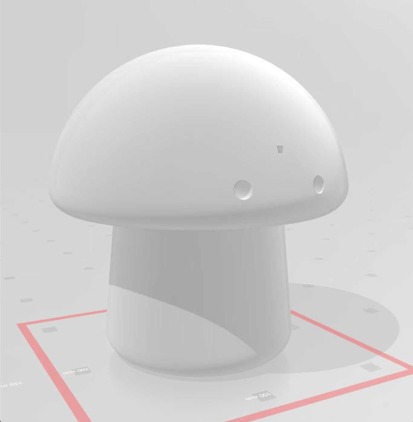

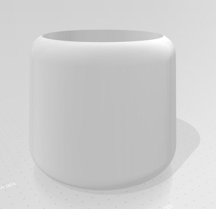
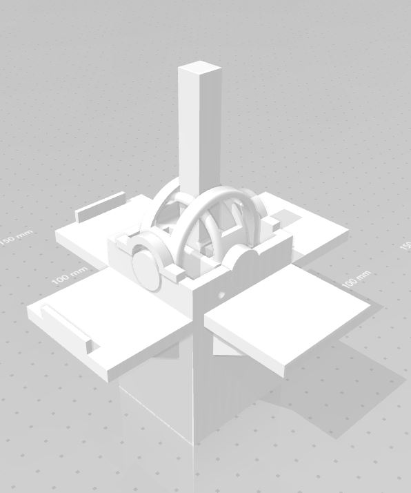
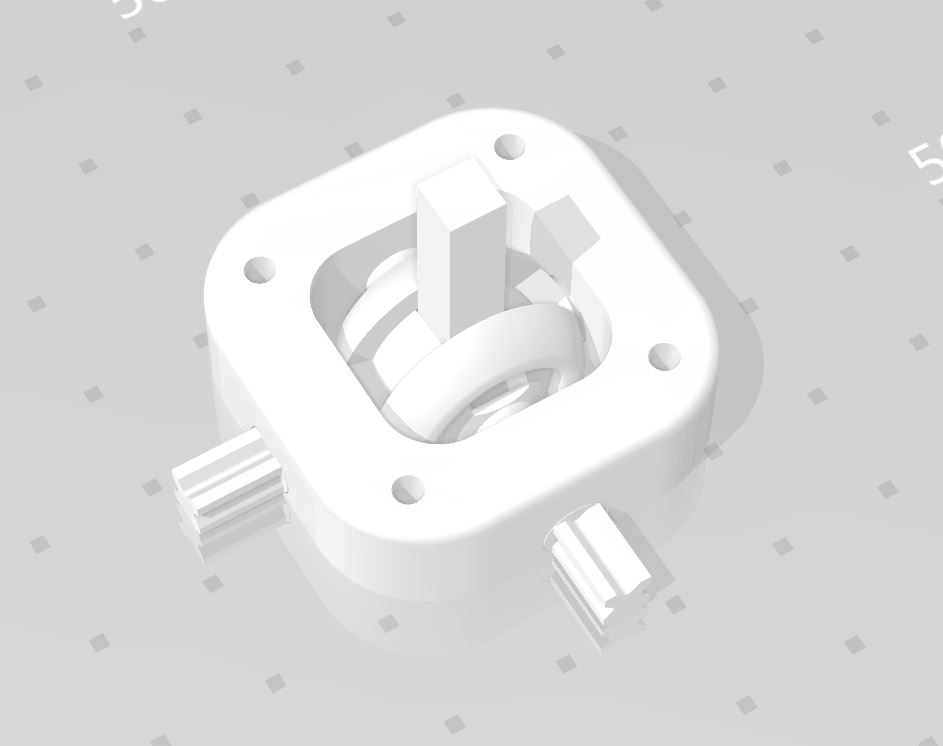
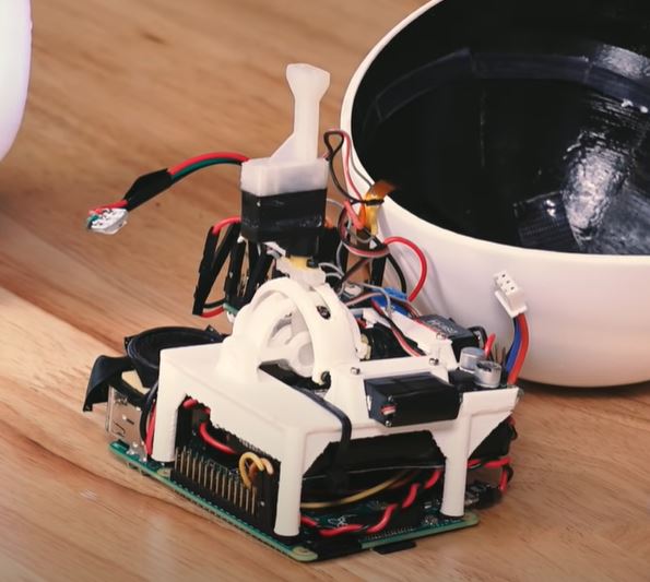
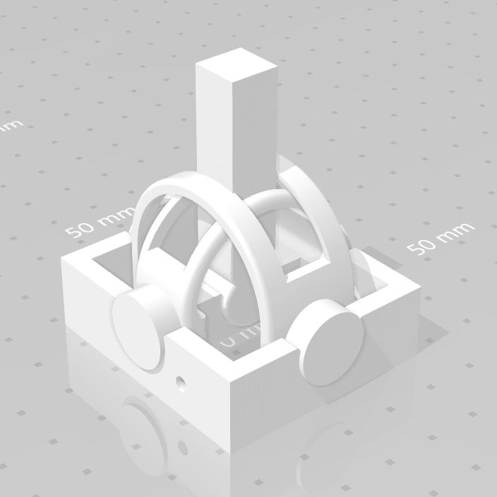
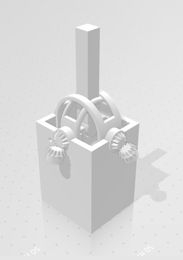
These are the key mechanical aspects/final chassis mock ups of the robot. All of the electrical systems for the robot’s function will be housed inside the chassis so that the aesthetic of a cute mushroom-shaped robot will be maintained.
[/av_textblock]
[av_heading tag=’h1′ padding=’10’ heading=’Requirements’ color=” style=’blockquote modern-quote’ custom_font=” size=” subheading_active=” subheading_size=’15’ custom_class=” admin_preview_bg=” av-desktop-hide=” av-medium-hide=” av-small-hide=” av-mini-hide=” av-medium-font-size-title=” av-small-font-size-title=” av-mini-font-size-title=” av-medium-font-size=” av-small-font-size=” av-mini-font-size=”][/av_heading]
[av_textblock size=” font_color=” color=” av-medium-font-size=” av-small-font-size=” av-mini-font-size=” admin_preview_bg=”]
The requirements include the applicable higher organization design codes and regulations, as well as the requirements specific to our robot. The Level 1 requirements are of high order and are provided for the mission, basic operation, assembly and disassembly, and logistics of the whole project. Level 2 requirements branch from the Level 1 requirements and show in greater detail the requirements involved in each Level 1 requirement.
[/av_textblock]
[av_heading tag=’h2′ padding=’10’ heading=’Engineering Standards and Constraints ‘ color=” style=’blockquote modern-quote’ custom_font=” size=” subheading_active=” subheading_size=’15’ custom_class=” admin_preview_bg=” av-desktop-hide=” av-medium-hide=” av-small-hide=” av-mini-hide=” av-medium-font-size-title=” av-small-font-size-title=” av-mini-font-size-title=” av-medium-font-size=” av-small-font-size=” av-mini-font-size=”][/av_heading]
[av_textblock size=” font_color=” color=” av-medium-font-size=” av-small-font-size=” av-mini-font-size=” admin_preview_bg=”]
The IloMilo Spring 2020 project team adheres to higher Engineering bodies that give standards, codes, and regulations when a toy is built. The applicable standards are listed below.
Applicable Engineering Standards
- Systems and Software Engineering — Life Cycle Processes –Requirements Engineering
- IEEE SCC21 – IEEE Approved Standard for Fuel Cells, Photovoltaics, Dispersed Generation, and Energy Storage
- NASA/SP-2007-6105 Rev1 – Systems Engineering Handbook
- Bluetooth Special Interest Group (SIG) Standard (supersedes IEEE 802.15.1)
- American Wire Gauge (AWG) Standard
- C++ standard (ISO/IEC 14882:1998)
- NXP Semiconductor, UM10204, I2C-bus specification and user manual.
- ATmega16U4/ATmega32U4, 8-bit Microcontroller with 16/32K bytes of ISP Flash and USB Controller datasheet section datasheet, Section 18, USART.
- USB 2.0 Specification released on April 27, 2000, usb_20_20180904.zip
- IEEE 29148-2018 – ISO/IEC/IEEE Approved Draft International Standard –
- Arduino De facto Standard scripting language and/or using the GCC C++ programming language, which is implements the ISO C++ standard (ISO/IEC 14882:1998) published in 1998, and the 2011 and 2014 revisions.
Environmental, Health, and Safety (EH&S) Standards
- CSULB COE Lab Safety
- CSULB Environmental Health & Safety
- IEEE National Electrical Safety Code
- NCEES Fundamental Handbook
- ASTM F963-17, compliant for Toy Safety
[/av_textblock]
[av_heading tag=’h2′ padding=’10’ heading=’Program Level 1 Requirements’ color=” style=’blockquote modern-quote’ custom_font=” size=” subheading_active=” subheading_size=’15’ custom_class=” admin_preview_bg=” av-desktop-hide=” av-medium-hide=” av-small-hide=” av-mini-hide=” av-medium-font-size-title=” av-small-font-size-title=” av-mini-font-size-title=” av-medium-font-size=” av-small-font-size=” av-mini-font-size=”][/av_heading]
[av_textblock size=” font_color=” color=” av-medium-font-size=” av-small-font-size=” av-mini-font-size=” admin_preview_bg=”]
Mission Requirements
| L1-1 | Ilo shall
use a paper bot drivetrain to move the robot forward and make right turns
|
| L1-2 | Ilo’s design shall include a custom shield to follow a copper grid line on the field of play
|
| L1-3 | Ilo shall stop at an intersection of the grid lines
|
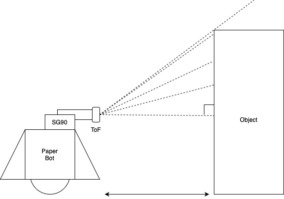
| L1-4 | Ilo shall use a Time of Flight sensor for object detection within 5 cm from the robot
|
| L1-5 | Ilo’s head shall be able to move independently of the drivetrain when attached to the joystick, similar to Alonzo Martinez’s joystick design. Ilo’s looks down 40 degrees (+/- 5 degrees) and up 40 degrees (+/- 5 degrees)
|
| L1-6 | Ilo shall make a 90 degree right turn (+/- 15%) when an obstacle is detected using the ToF sensor
|
| L1-7 | Ilo shall recognize Milo by measuring his height and stopping
|
| L1-8 | Ilo shall find Milo in less than 20 minutes
|
Basic Operation Requirements
| L1-9 | Ilo shall utilize an OLED programmed to display a blinking eye
|
| L1-10 | Ilo will utilize the 3Dot board
|
Assembly & Disassembly Requirements
| L1-11 | Ilo shall be assembled and disassembled within 20 minutes with no dangling or exposed wires
|
| L1-12 | Ilo’s chassis will easily fit over the paper bot and sit on the top of the paper bot shell
|
| L1-13 | Ilo’s head, joystick, and chassis will be 3D printed using ABS
|
Logistics Requirements
| L1-14 | The whole project shall not exceed a total cost of $500
|
| L1-15 | Ilo shall complete the mission by Monday, May 11th.
|
[/av_textblock]
[av_heading tag=’h2′ padding=’10’ heading=’System/Subsystem/Specifications Level 2 Requirements’ color=” style=’blockquote modern-quote’ custom_font=” size=” subheading_active=” subheading_size=’15’ custom_class=” admin_preview_bg=” av-desktop-hide=” av-medium-hide=” av-small-hide=” av-mini-hide=” av-medium-font-size-title=” av-small-font-size-title=” av-mini-font-size-title=” av-medium-font-size=” av-small-font-size=” av-mini-font-size=”][/av_heading]
[av_textblock size=” font_color=” color=” av-medium-font-size=” av-small-font-size=” av-mini-font-size=” admin_preview_bg=”]
Mission Requirements
| L2-1 | 1 | The Paper bot drive train will use plastic gear motors
|
| 2 | The Paper bot plastic gear motors will be connected to the Dual Motor Driver headers on the 3 dot | |
| L2-2 | 1 | The custom shield shall be designed in Eagle CAD |
| 2 | The custom shield shall be designed with SMD components | |
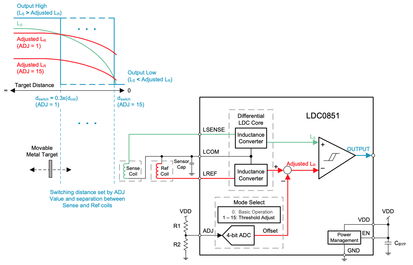
| 3 | The custom shield shall utilize the TI LDC0851 Inductance to Digital Converter Integrated Circuit | |
| 4 | The LDC shield will be connected to the 3 Dot by the Sensing Header J3 | |
| L2-3 | 1 | Grid lines will be laid out perpendicularly so that all angles are 90 degrees |
| 2 | Grid lines will be made of copper tape that is at least 1” thick | |
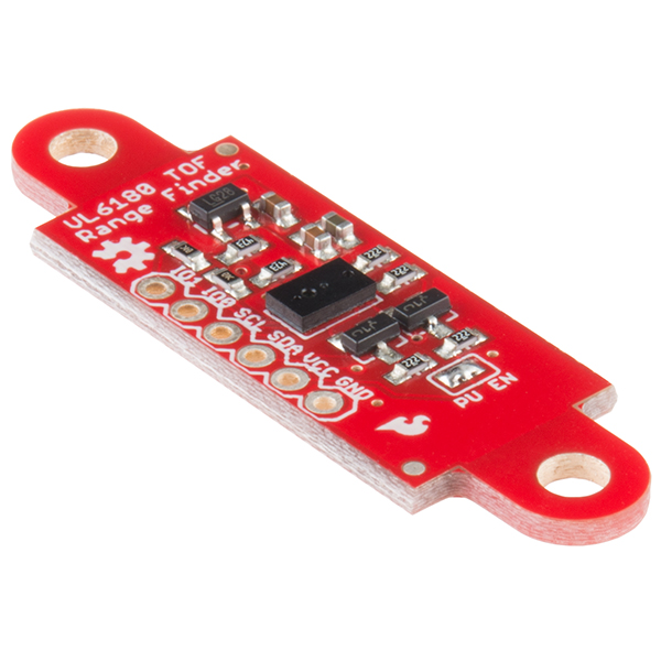
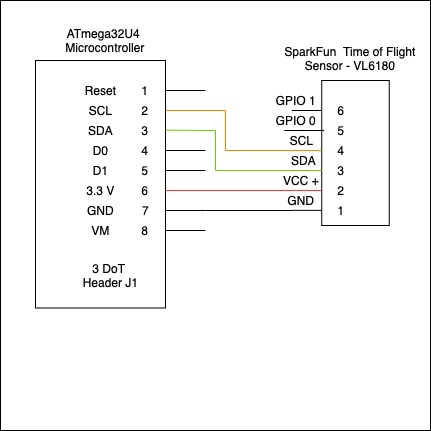
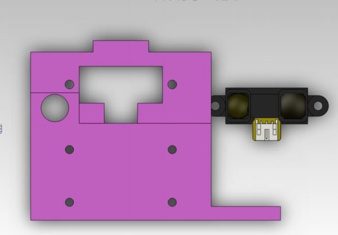
| L2-4 | 1 | The Time of Flight sensor will be the Spark Fun VL6180 ToF Sensor breakout board |
| 2 | The ToF sensor will be placed in the head of the robot where the sensor is able to read distance | |
| 3 | The ToF sensor will be programmed using 12C communication in Arduino IDE | |
| 4 | The ToF sensor will be connected to the 3 Dot board for 12C communication | |
| L2-5 | 1 | The joystick shall utilize two servos, one to move front to back (“nodding”, Servo 1), and one to move side to side (Servo 2). Both directions will pivot on the joystick’s axis.
|
| 2 | Servo 1 will be connected to the Servo 1 header on the 3 Dot and Servo 2 will be connected to the Servo 2 header on the 3 Dot. | |
| 3 | The servos will be SG90’s | |
| 4 | The joystick servos will be programmed in Arduino IDE. | |
| L2-6 | 1 | An obstacle will be distinguished by its height. If the height is not between 40 and 54 cm it is an obstacle. |
| 2 | The LDC shield will keep the robot following the grid line when making the right turn if the robot over or under turns | |
| L2-7 | 1 | Milo’s height will be programmed to be between 40 and 54 cm. |
| 2 | Milo will be a box with a height between 40 and 54 cm, simulating the other robot. |
Basic Operation Requirements
| L2-9 | 1 | The OLED will use SPI communication |
| 2 | The OLED will be the Crystalfontz CFAL4864A-071BW Small 48×64 .71inch OLED Display. | |
| 3 | The OLED will be connected to the 3 Dot board via the Crystalfontz CFA10054 breakout board | |
| L2-10 | 1 | All electrical components will be controlled by the pre programmed 3 Dot MCU |
| 2 | All electrical components will run power from the 3 Dot board |
Assembly & Disassembly Requirements
| L2-11 | 1 | The ToF sensor board will be placed in the robot’s “forehead” with the sensor itself reading through the small hole made for the sensor |
| 2 | The OLEDs will be connected behind the eye holes in the robot’s head | |
| 3 | The chassis will be a separate part from the joystick and the head of the robot. | |
| 4 | The joystick will be connected to the chassis and the head will be connected to the joystick | |
| 5 | All wires will run down through the robot and paper bot’s chassis to be connected to the 3 Dot | |
| L2-12 | 1 | The chassis will be stable on top of the paper bot chassis and contain the whole paper bot chassis |
| 2 | The robot chassis will not fall off the paper bot chassis when the robot moves forward, turns, or measures objects. |
[/av_textblock]
[av_heading tag=’h2′ padding=’10’ heading=’Allocated Requirements / System Resource Reports’ color=” style=’blockquote modern-quote’ custom_font=” size=” subheading_active=” subheading_size=’15’ custom_class=” admin_preview_bg=” av-desktop-hide=” av-medium-hide=” av-small-hide=” av-mini-hide=” av-medium-font-size-title=” av-small-font-size-title=” av-mini-font-size-title=” av-medium-font-size=” av-small-font-size=” av-mini-font-size=”][/av_heading]
[av_heading tag=’h3′ padding=’10’ heading=’Mass Shared Resource Report / Allocation’ color=” style=’blockquote modern-quote’ custom_font=” size=” subheading_active=” subheading_size=’15’ custom_class=” admin_preview_bg=” av-desktop-hide=” av-medium-hide=” av-small-hide=” av-mini-hide=” av-medium-font-size-title=” av-small-font-size-title=” av-mini-font-size-title=” av-medium-font-size=” av-small-font-size=” av-mini-font-size=”][/av_heading]
[av_textblock size=” font_color=” color=” av-medium-font-size=” av-small-font-size=” av-mini-font-size=” admin_preview_bg=”]
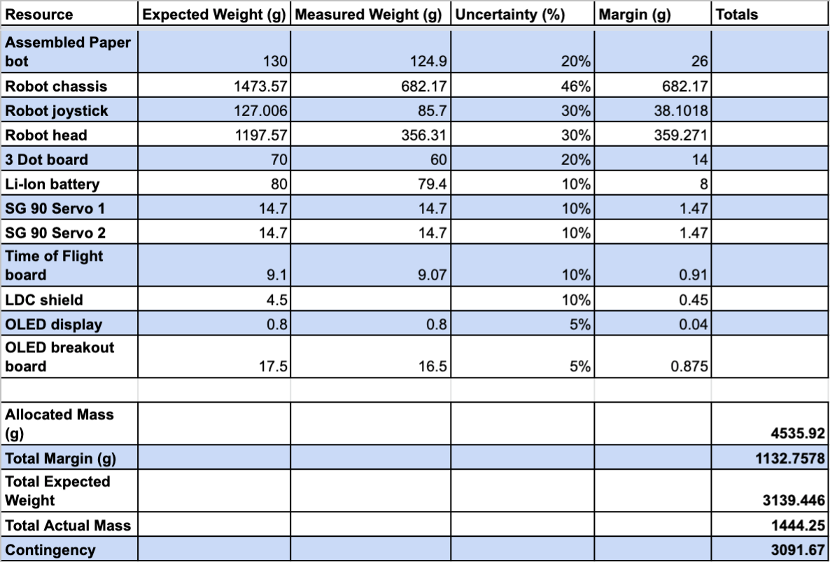
There was no real constraint for the mass of our robot because it will be performing its whole mission on the ground, autonomously. We chose to allocate 10 lbs (4535.92 g) because this would still be light enough for the average child to be able to lift it without too much. As shown by the table though, the total mass was much less than the allocated mass.
[/av_textblock]
[av_heading tag=’h3′ padding=’10’ heading=’Power Shared Resource Report / Allocation’ color=” style=’blockquote modern-quote’ custom_font=” size=” subheading_active=” subheading_size=’15’ custom_class=” admin_preview_bg=” av-desktop-hide=” av-medium-hide=” av-small-hide=” av-mini-hide=” av-medium-font-size-title=” av-small-font-size-title=” av-mini-font-size-title=” av-medium-font-size=” av-small-font-size=” av-mini-font-size=”][/av_heading]
[av_textblock size=” font_color=” color=” av-medium-font-size=” av-small-font-size=” av-mini-font-size=” admin_preview_bg=”]
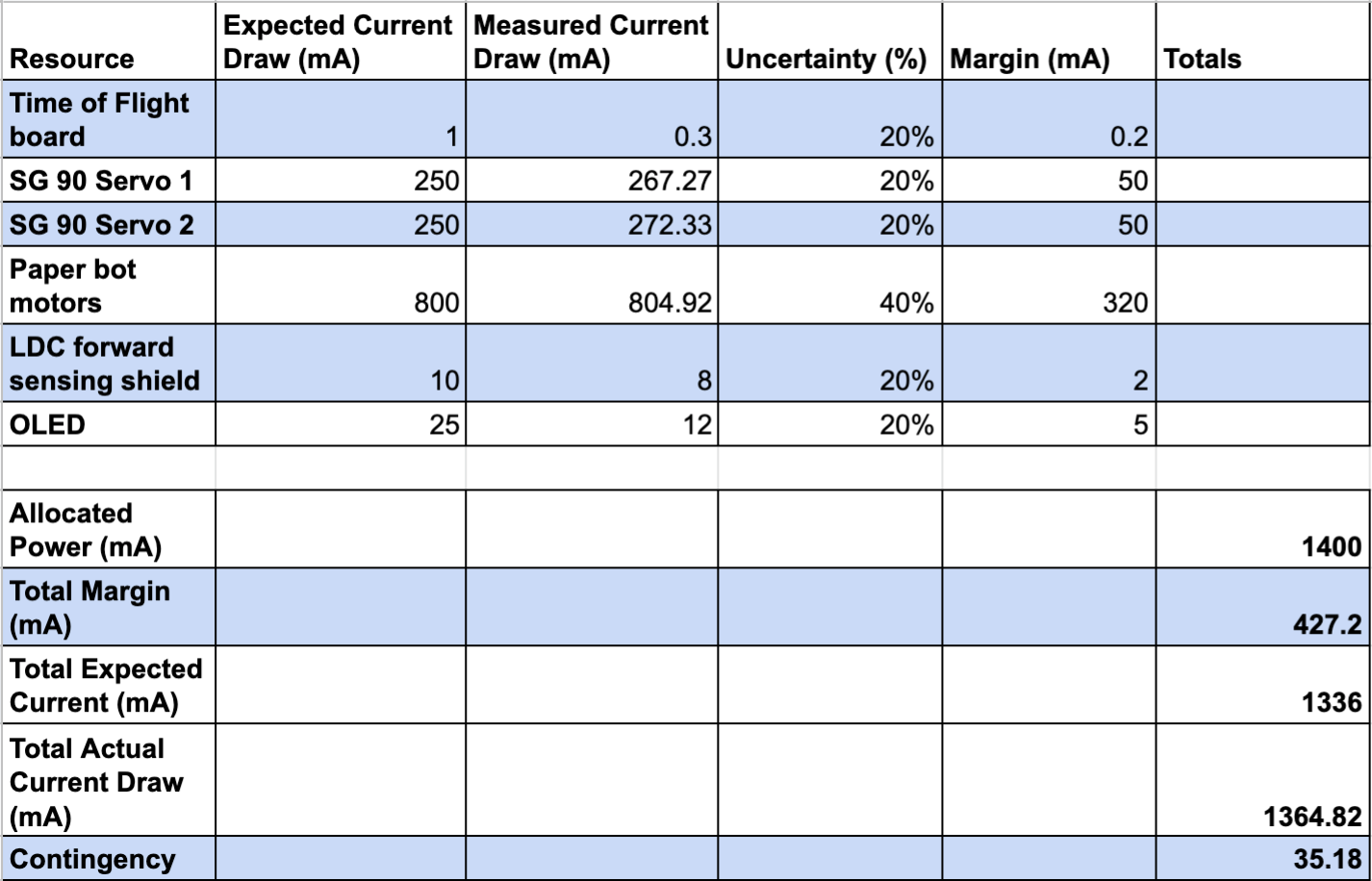
The power allocation breakdown details the allocated power by the Li-Ion battery for the robot to be powered for 30 minutes. Since our mission is required to be completed within 20 minutes this power time will be sufficient with a modest contingency.
[/av_textblock]
[av_heading tag=’h1′ padding=’10’ heading=’Project Report’ color=” style=’blockquote modern-quote’ custom_font=” size=” subheading_active=” subheading_size=’15’ custom_class=” admin_preview_bg=” av-desktop-hide=” av-medium-hide=” av-small-hide=” av-mini-hide=” av-medium-font-size-title=” av-small-font-size-title=” av-mini-font-size-title=” av-medium-font-size=” av-small-font-size=” av-mini-font-size=”][/av_heading]
[av_textblock size=” font_color=” color=” av-medium-font-size=” av-small-font-size=” av-mini-font-size=” admin_preview_bg=”]
This section includes all of the over all logistics of the project including Work Breakdown Structure (WBS), Product Breakdown Structure (PBS), Cost breakdown, and Project schedule. This section should give the details of what work is to be done, when the work is to be done, what products are to be delivered and when they are to be delivered.
[/av_textblock]
[av_heading tag=’h2′ padding=’10’ heading=’Project WBS and PBS’ color=” style=’blockquote modern-quote’ custom_font=” size=” subheading_active=” subheading_size=’15’ custom_class=” admin_preview_bg=” av-desktop-hide=” av-medium-hide=” av-small-hide=” av-mini-hide=” av-medium-font-size-title=” av-small-font-size-title=” av-mini-font-size-title=” av-medium-font-size=” av-small-font-size=” av-mini-font-size=”][/av_heading]
[av_textblock size=” font_color=” color=” av-medium-font-size=” av-small-font-size=” av-mini-font-size=” admin_preview_bg=”]
Work Breakdown Structure (WBS)
The WBS breaks down the major work involved for each division of the project.
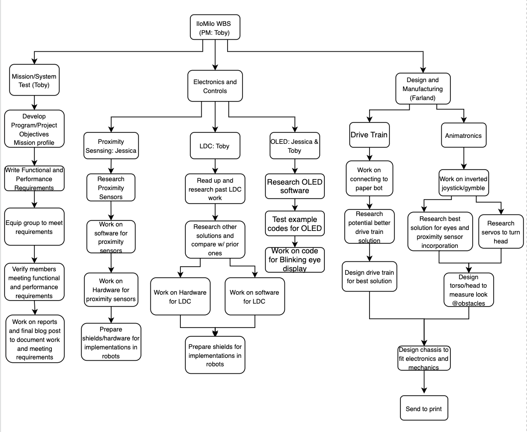
Proximity Sensing (Jessica)
Jessica will research the Time of Flight sensors and see to what extent they can be used to measure objects as well as their own distance from objects. Initially, Jessica will connect the robots to the Arxterra app and allow their movement to be user-controlled. She will then develop the software to program the time of flight sensors to measure the height and width of objects as well as their own distance from the object. From the software development, she will connect the sensors to the 3Dot board or another shield, depending on the most efficient implementation. Finally, she will get the sensors ready to be implemented into the final robot design so that it will autonomously navigate around obstacles and find the other robot.
LDC (Toby)
Toby will first read up on previous semesters’ work on the Inductance to Digital Converter (LDC). He will then research better implementations and designs as well as what is available on the market and decide on what is the best design for detecting a copper grid under the field of play. He will then develop the software and new LDC shield to detect the copper grid and then finally prepare it to be implemented in the final robot design.
OLED (Toby & Jessica)
Jessica will first research OLED displays, hardware, and software, that will best suit the robot. Jessica and Toby will both then research the software to make the OLED display a blinking eye. After researching this they will work on programming the display to look like a blinking eye until they arrive at a result that improves the overall animated aesthetics of the robot.
Drive Train & Animatronics (Farland)
Farland will design two major mechanical aspects for the IloMilo robots.
For the drive train, Farland will start by using the caster system of Paper Bot and research if this base will be the best design to mount the rest of the chassis of the robot on. If it is not, he will design a new drive train system, including motors and casters to better support the rest of the chassis.
For the animatronics, Farland will research and design an inverted joystick/gimble to enable the head of the robot to move in virtually every direction. He will then research the best way to implement the TOF sensors into the head of the robots as well as the best servos to control the movement of the head. Finally, he will create the final design to incorporate all the mechanical and electrical components into the chassis of each robot.
Product Breakdown Structure (PBS)
The PBS breaks down the products to be delivered for the project as well as what version of the project they are to be delivered for.
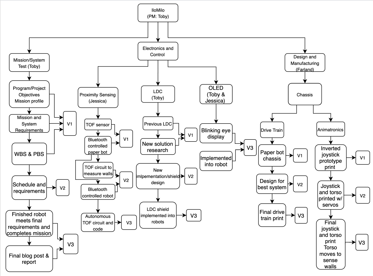
V1 Products:
- Program/Project Objectives and Mission Profile
- Program/Project and Mission requirements
- WBS and PBS
- TOF sensor sensing objects
- Bluetooth controlled Paper Bot
- Previous LDC shield
- Initial research for new LDC
- Inverted joystick prototype w/ servos
V2 Products:
- Finalized schedule and requirements
- TOF software and hardware to measure walls and sense distance
- New LDC shield design
- Design for best drive train system
- Joystick w/ servos moving entire head of robot
V3 Products:
- Final blog post and report
- Verify robots meet final requirements
- Inverted joystick prototype w/ servos
- TOF sensor implemented into robot navigates maze autonomously
- LDC shield implemented into robot to keep it on the invisible copper grid
- OLED programmed to look like blinking eye and implemented into robot’s head
- Drive train printed and assembled in chassis
- Chassis printed and assembled
- houses all components
- can look around to sense the obstacles and other robot in the field field
[/av_textblock]
[av_heading tag=’h2′ padding=’10’ heading=’Cost’ color=” style=’blockquote modern-quote’ custom_font=” size=” subheading_active=” subheading_size=’15’ custom_class=” admin_preview_bg=” av-desktop-hide=” av-medium-hide=” av-small-hide=” av-mini-hide=” av-medium-font-size-title=” av-small-font-size-title=” av-mini-font-size-title=” av-medium-font-size=” av-small-font-size=” av-mini-font-size=”][/av_heading]
[av_textblock size=” font_color=” color=” av-medium-font-size=” av-small-font-size=” av-mini-font-size=” admin_preview_bg=”]
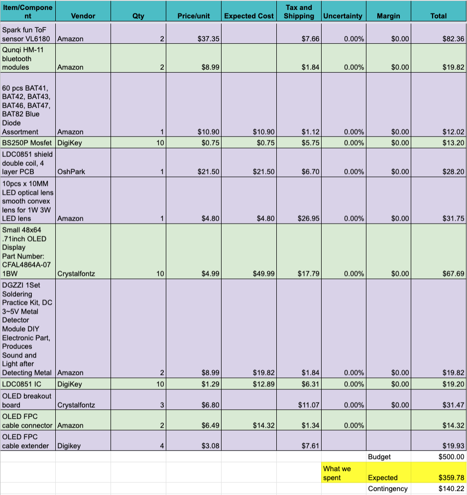
Expenditure Report
[/av_textblock]
[av_heading tag=’h2′ padding=’10’ heading=’Schedule’ color=” style=’blockquote modern-quote’ custom_font=” size=” subheading_active=” subheading_size=’15’ custom_class=” admin_preview_bg=” av-desktop-hide=” av-medium-hide=” av-small-hide=” av-mini-hide=” av-medium-font-size-title=” av-small-font-size-title=” av-mini-font-size-title=” av-medium-font-size=” av-small-font-size=” av-mini-font-size=”][/av_heading]
[av_textblock size=” font_color=” color=” av-medium-font-size=” av-small-font-size=” av-mini-font-size=” admin_preview_bg=”]
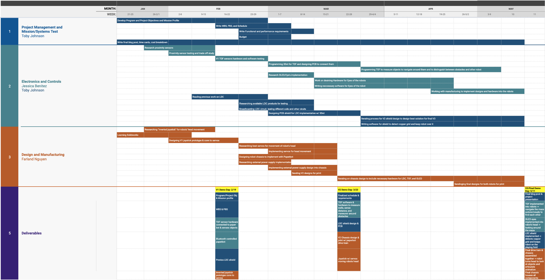
Project Schedule
[/av_textblock]
[av_heading tag=’h1′ padding=’10’ heading=’Concept and Preliminary Design’ color=” style=’blockquote modern-quote’ custom_font=” size=” subheading_active=” subheading_size=’15’ custom_class=” admin_preview_bg=” av-desktop-hide=” av-medium-hide=” av-small-hide=” av-mini-hide=” av-medium-font-size-title=” av-small-font-size-title=” av-mini-font-size-title=” av-medium-font-size=” av-small-font-size=” av-mini-font-size=”][/av_heading]
[av_textblock size=” font_color=” color=” av-medium-font-size=” av-small-font-size=” av-mini-font-size=” admin_preview_bg=”]
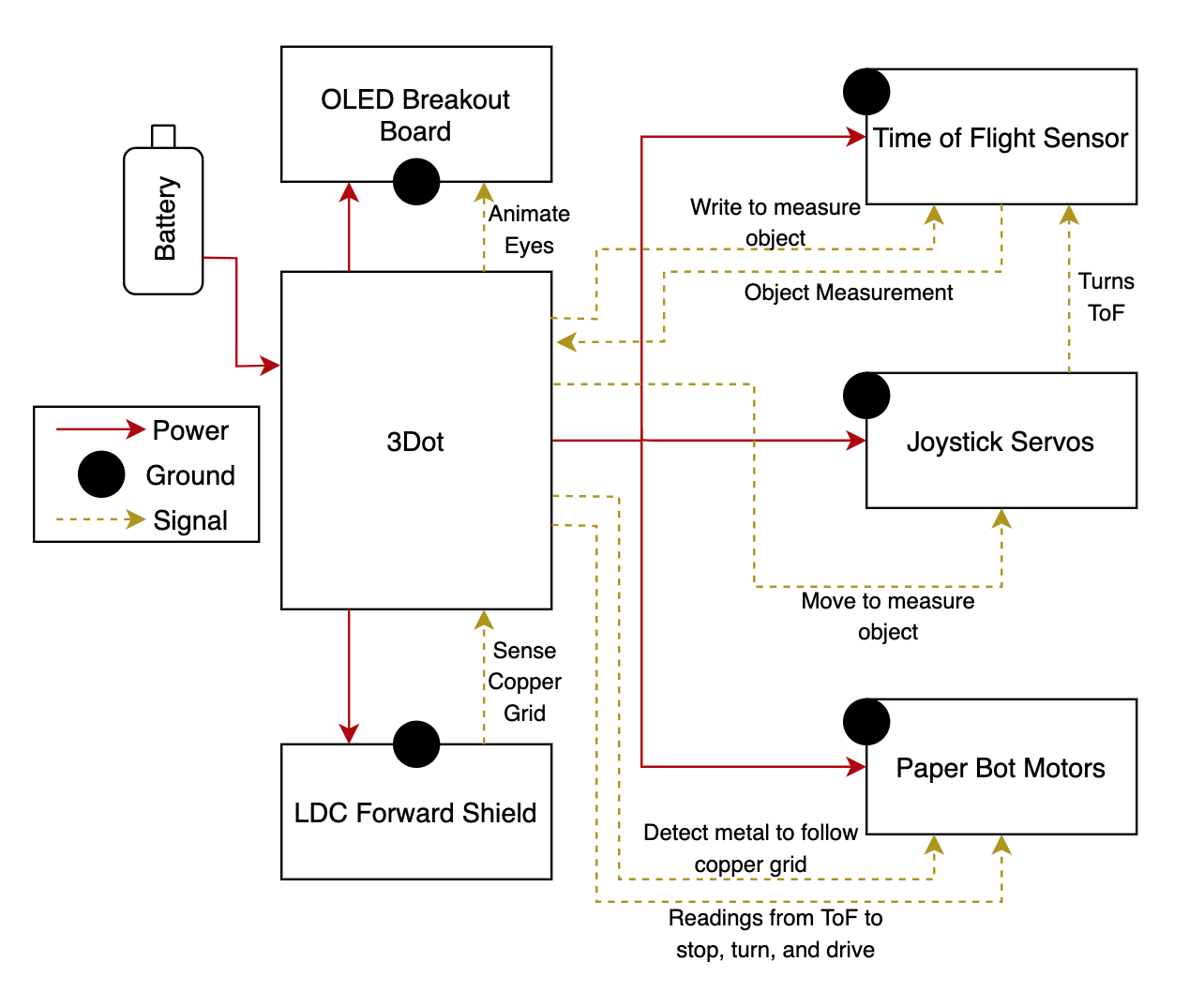
This basic block diagram shows the systems of the robot as well as power, ground, and basic communication signal definitions. There are 5 electronic systems connected to the 3 Dot board that will be programmed by its MCU. These 5 systems will also have to be powered by the 3 Dot battery.
[/av_textblock]
[av_heading tag=’h2′ padding=’10’ heading=’Literature Review’ color=” style=’blockquote modern-quote’ custom_font=” size=” subheading_active=” subheading_size=’15’ custom_class=” admin_preview_bg=” av-desktop-hide=” av-medium-hide=” av-small-hide=” av-mini-hide=” av-medium-font-size-title=” av-small-font-size-title=” av-mini-font-size-title=” av-medium-font-size=” av-small-font-size=” av-mini-font-size=”][/av_heading]
[av_textblock size=” font_color=” color=” av-medium-font-size=” av-small-font-size=” av-mini-font-size=” admin_preview_bg=”]
The majority of engineering work was done on the Time of Flight sensor, by Jessica, the LDC shield, by Toby, and the joystick design, by Farland. Each of these elements have much more thoroughly detailed blog posts that describe the theory and design process.
[/av_textblock]
[av_heading tag=’h2′ padding=’10’ heading=’Design Innovation’ color=” style=’blockquote modern-quote’ custom_font=” size=” subheading_active=” subheading_size=’15’ custom_class=” admin_preview_bg=” av-desktop-hide=” av-medium-hide=” av-small-hide=” av-mini-hide=” av-medium-font-size-title=” av-small-font-size-title=” av-mini-font-size-title=” av-medium-font-size=” av-small-font-size=” av-mini-font-size=”][/av_heading]
[av_textblock size=” font_color=” color=” av-medium-font-size=” av-small-font-size=” av-mini-font-size=” admin_preview_bg=”]
One of the crucial elements of the design process was choosing the right proximity sensor for our application. Jessica wrote a detailed blog post documenting our robot’s requirements for the mission and how the options for proximity sensors fulfilled them as well as the sensor we ultimately decided to implement.
Proximity Sensor trade-off study Blog Post
Another crucial element of the design process was the joystick that would enable the movement of the robot’s head. According to our requirements, our robot would have to be able to move its head independently of the drive train. The inspiration for this joystick came from Alonzo Martinez’s animated robots. Alonzo did not share his designs, however, so Farland moved to designing a joystick more suitable for our robot himself.
Joystick Design Blog Post
[/av_textblock]
[av_heading tag=’h2′ padding=’10’ heading=’Conceptual Design / Proposed Solution’ color=” style=’blockquote modern-quote’ custom_font=” size=” subheading_active=” subheading_size=’15’ custom_class=” admin_preview_bg=” av-desktop-hide=” av-medium-hide=” av-small-hide=” av-mini-hide=” av-medium-font-size-title=” av-small-font-size-title=” av-mini-font-size-title=” av-medium-font-size=” av-small-font-size=” av-mini-font-size=”][/av_heading]
[av_textblock size=” font_color=” color=” av-medium-font-size=” av-small-font-size=” av-mini-font-size=” admin_preview_bg=”]
The new innovative concepts utilizing the Time of Flight proximity sensor and designing the joystick, as shown by the previously linked blog posts, enable our robot to complete its mission. The time of flight allows for accurate height and distance measurements as required by our mission and the joystick enables the time of flight to move and measure objects, while maintaining the aesthetic of the robot, as the only system observable from the outside is the robot’s chassis.
[/av_textblock]
[av_heading tag=’h1′ padding=’10’ heading=’System Design / Final Design and Results’ color=” style=” custom_font=” size=” subheading_active=” subheading_size=’15’ custom_class=” admin_preview_bg=” av-desktop-hide=” av-medium-hide=” av-small-hide=” av-mini-hide=” av-medium-font-size-title=” av-small-font-size-title=” av-mini-font-size-title=” av-medium-font-size=” av-small-font-size=” av-mini-font-size=”][/av_heading]
[av_textblock size=” font_color=” color=” av-medium-font-size=” av-small-font-size=” av-mini-font-size=” admin_preview_bg=”]
The final design incorporates all of the systems shown in the block diagram below and satisfies all of our requirements.
Major Subsystems:
- Time of Flight Sensor
The ToF sensor is able to measure distance accurately to distinguish which objects are obstacles and which is the other robot. It is also able to communicate through the 3 Dot MCU, the height data and then whether the robot should turn to continue its search or stop because it has found the other robot.
- Joystick
The final joystick design is quite large in order to support and move the robot’s entire head, which is also large as to have enough space to house all the components. The joystick is moved by two SG90 servos that move according to the ToF sensor to measure the height of objects.
- LDC Forward Sensing Shield
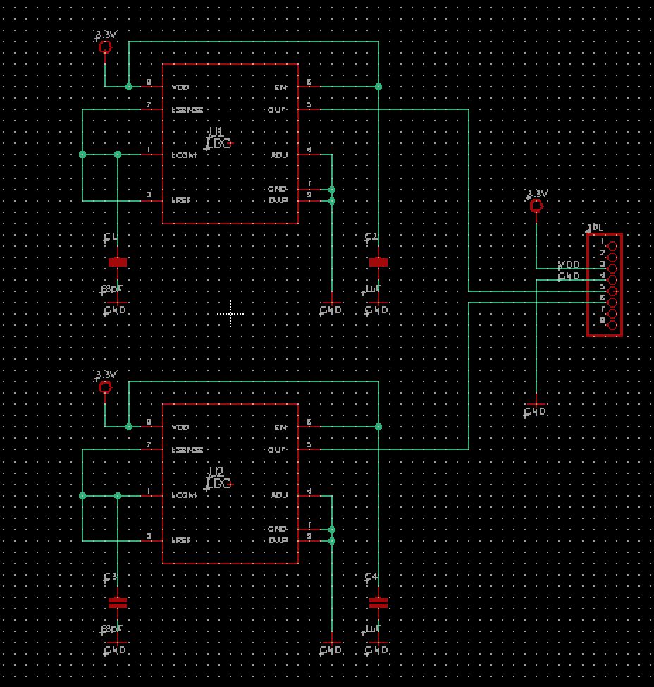
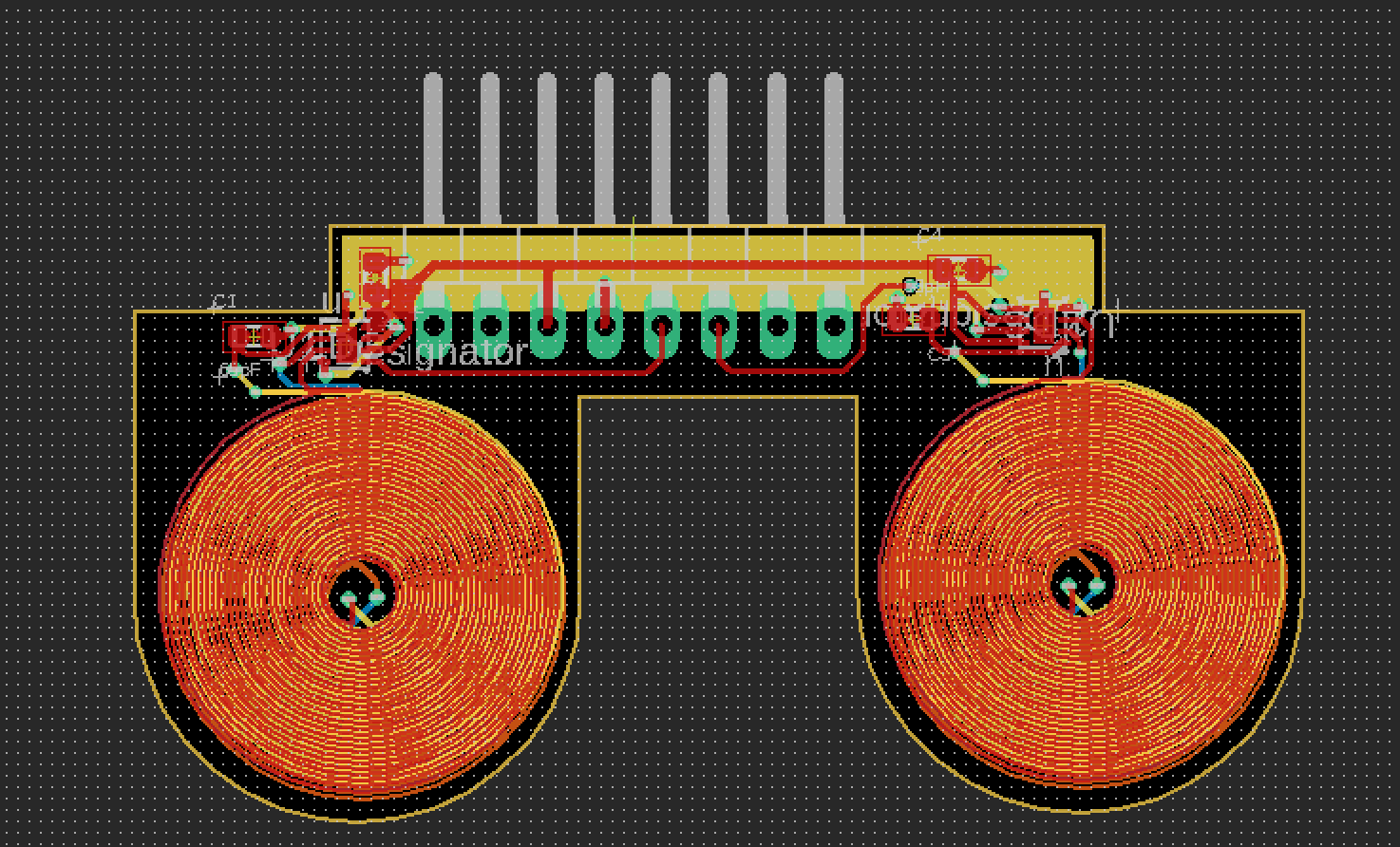
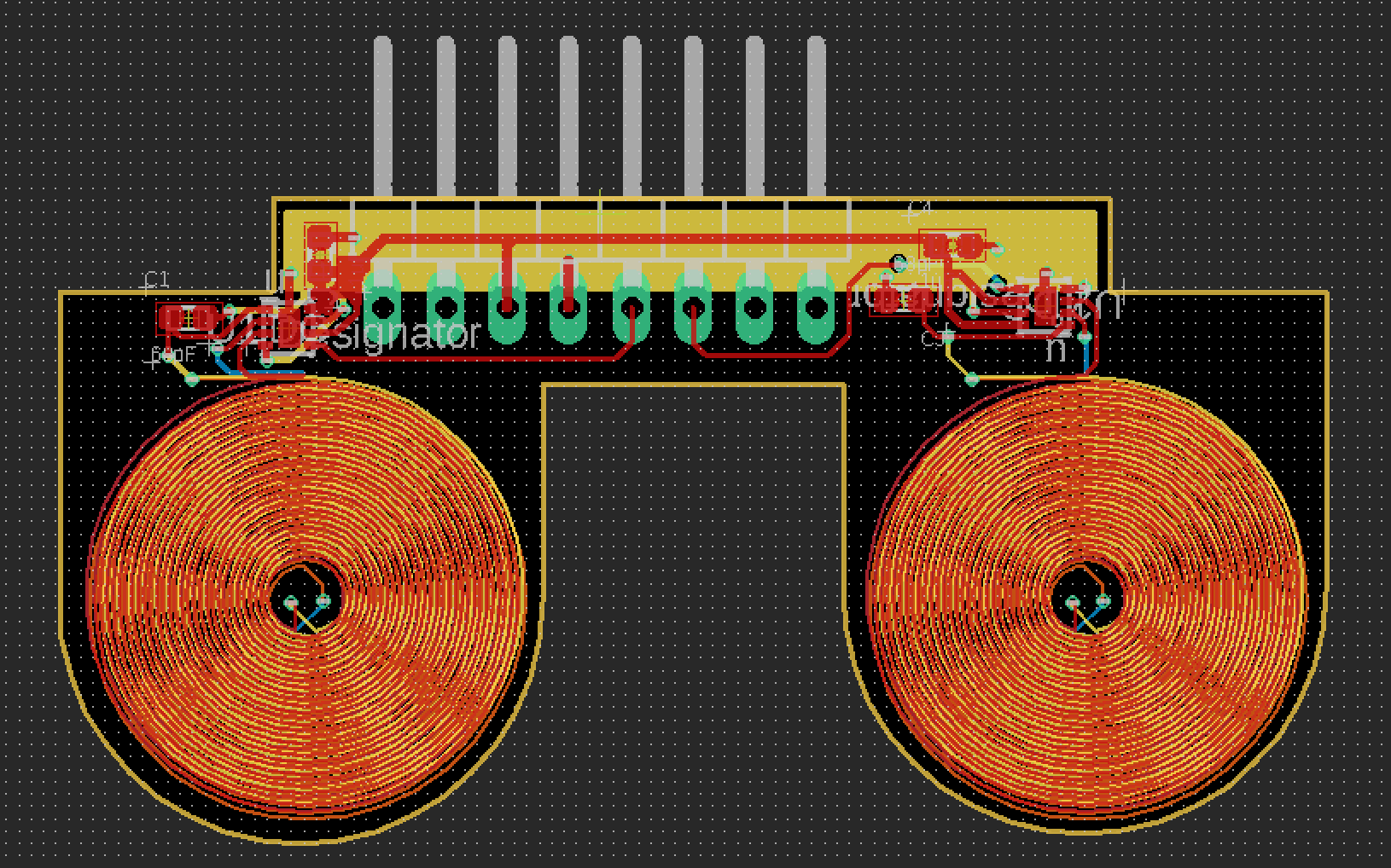
The final LDC shield PCB was a result of several iterations of the design. The main feature of the design is the use two of Texas Instrument’s LDC0851 integrated circuits as these chips were designed precisely for small distance, contactless metal detection. The use of these chips also simplifies the PCB design significantly as each chip only requires two capacitors for filtering.
- OLED
The OLED simply adds to the fun animated aesthetic of the robot. When the OLED is programmed to look like a blinking eye, the robot comes to life and has personality to it.
[/av_textblock]
[av_heading tag=’h2′ padding=’10’ heading=’System Block Diagram’ color=” style=” custom_font=” size=” subheading_active=” subheading_size=’15’ custom_class=” admin_preview_bg=” av-desktop-hide=” av-medium-hide=” av-small-hide=” av-mini-hide=” av-medium-font-size-title=” av-small-font-size-title=” av-mini-font-size-title=” av-medium-font-size=” av-small-font-size=” av-mini-font-size=”][/av_heading]
[av_textblock size=” font_color=” color=” av-medium-font-size=” av-small-font-size=” av-mini-font-size=” admin_preview_bg=”]
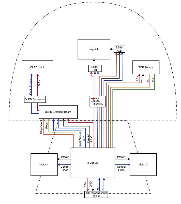
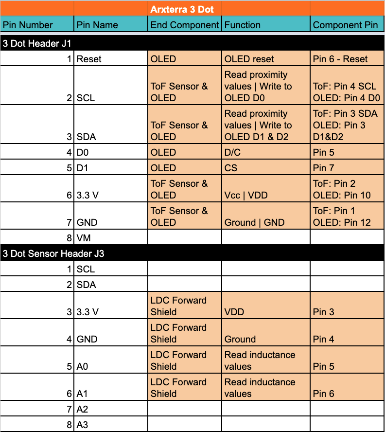
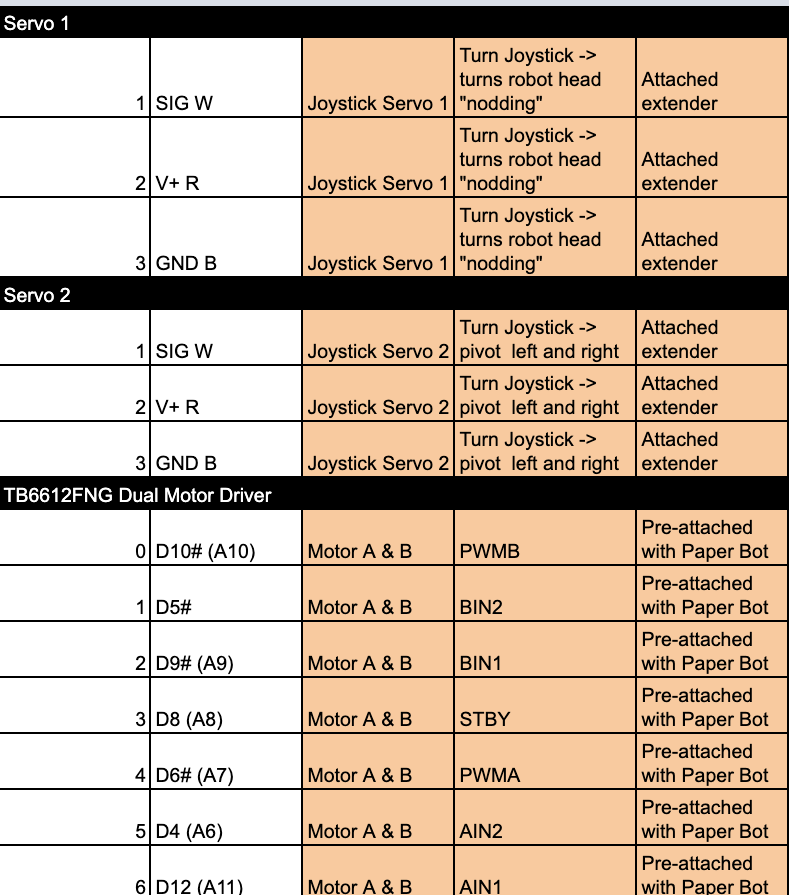
As shown by the system block diagram, all of the systems of the robot are connected to the 3 Dot board. The specific connections are defined in the interface matrix. One of the key system interactions is between the Time of Flight sensor and the joystick. This is because the joystick has to move the head of the robot in order for the ToF to measure the objects’ heights. The ToF sensor will have to communicate with the joystick servos through the 3 Dot MCU to move the head up while measuring an object. The ToF will also then have to communicate with the Paper bot motors to turn when an object is recognized as an obstacle. Additionally, the LDC forward shield will have to communicate with the Paper bot motors in order to keep the robot following the copper grid. If the robot starts to move off the line to one direction or the other the LDC shield will detect the copper tape and cause the motors to correct the robot’s path. The LDC shield will also detect an intersection in the copper grid and cause the Paper bot motors to stop before continuing on its forward path.
[/av_textblock]
[av_heading tag=’h2′ padding=’10’ heading=’Interface Definition’ color=” style=” custom_font=” size=” subheading_active=” subheading_size=’15’ custom_class=” admin_preview_bg=” av-desktop-hide=” av-medium-hide=” av-small-hide=” av-mini-hide=” av-medium-font-size-title=” av-small-font-size-title=” av-mini-font-size-title=” av-medium-font-size=” av-small-font-size=” av-mini-font-size=”][/av_heading]
[av_textblock size=” font_color=” color=” av-medium-font-size=” av-small-font-size=” av-mini-font-size=” admin_preview_bg=”]
[/av_textblock]
[av_heading tag=’h1′ padding=’10’ heading=’Modeling/Experimental Results’ color=” style=” custom_font=” size=” subheading_active=” subheading_size=’15’ custom_class=” admin_preview_bg=” av-desktop-hide=” av-medium-hide=” av-small-hide=” av-mini-hide=” av-medium-font-size-title=” av-small-font-size-title=” av-mini-font-size-title=” av-medium-font-size=” av-small-font-size=” av-mini-font-size=”][/av_heading]
[av_textblock size=” font_color=” color=” av-medium-font-size=” av-small-font-size=” av-mini-font-size=” admin_preview_bg=”]
Electronic Systems Modeling
Manufacturing Systems Modeling
[/av_textblock]
[av_heading tag=’h1′ padding=’10’ heading=’Mission Command and Control’ color=” style=” custom_font=” size=” subheading_active=” subheading_size=’15’ custom_class=” admin_preview_bg=” av-desktop-hide=” av-medium-hide=” av-small-hide=” av-mini-hide=” av-medium-font-size-title=” av-small-font-size-title=” av-mini-font-size-title=” av-medium-font-size=” av-small-font-size=” av-mini-font-size=”][/av_heading]
[av_textblock size=” font_color=” color=” av-medium-font-size=” av-small-font-size=” av-mini-font-size=” admin_preview_bg=”]
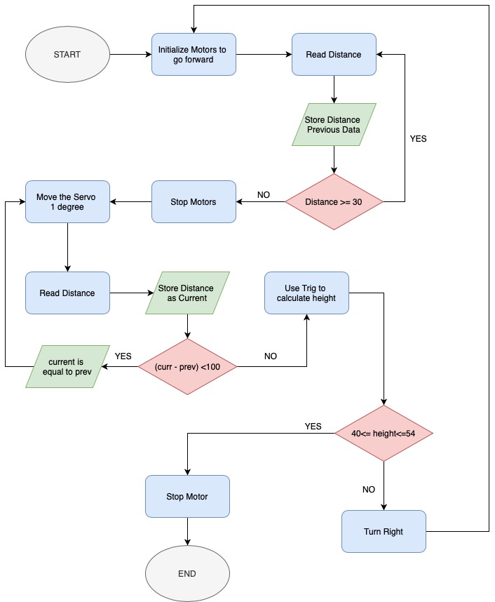
Because the robots will be completely autonomous, all of Mission Control is pre-programmed in software. The software flow diagram shows the process by which the robot completes the mission. The final code files will be provided in the reference section at the end of the post.

[/av_textblock]
[av_heading tag=’h1′ padding=’10’ heading=’Electronic Design’ color=” style=” custom_font=” size=” subheading_active=” subheading_size=’15’ custom_class=” admin_preview_bg=” av-desktop-hide=” av-medium-hide=” av-small-hide=” av-mini-hide=” av-medium-font-size-title=” av-small-font-size-title=” av-mini-font-size-title=” av-medium-font-size=” av-small-font-size=” av-mini-font-size=”][/av_heading]
[av_textblock size=” font_color=” color=” av-medium-font-size=” av-small-font-size=” av-mini-font-size=” admin_preview_bg=”]
This section details the custom shield design for the LDC PCB. The basic design was iterated upon from a previous metal detector forward sensing shield.
[/av_textblock]
[av_heading tag=’h2′ padding=’10’ heading=’PCB Design’ color=” style=” custom_font=” size=” subheading_active=” subheading_size=’15’ custom_class=” admin_preview_bg=” av-desktop-hide=” av-medium-hide=” av-small-hide=” av-mini-hide=” av-medium-font-size-title=” av-small-font-size-title=” av-mini-font-size-title=” av-medium-font-size=” av-small-font-size=” av-mini-font-size=”][/av_heading]
[av_textblock size=” font_color=” color=” av-medium-font-size=” av-small-font-size=” av-mini-font-size=” admin_preview_bg=”]
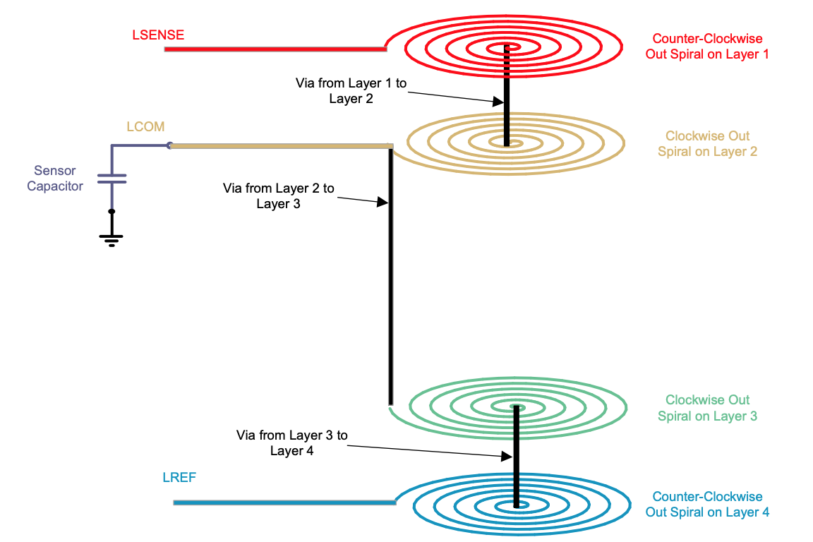
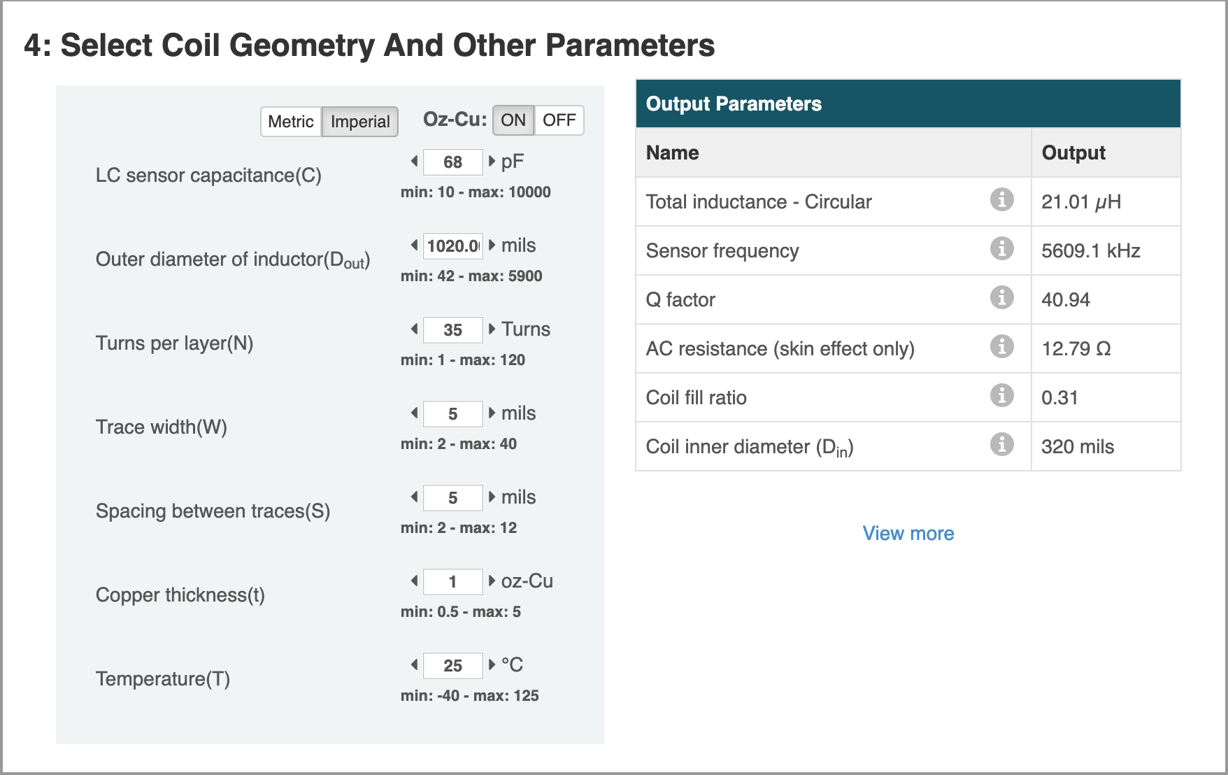
According to the requirements, the custom shield was designed in Eagle CAD. Because of limited time and limits of the surface mount IC the PCB was designed off of the detailed documentation from Texas Instruments on the LDC0851 and its typical applications. The Eagle CAD files for the schematic and PCB are included at the end of the document and a detailed rundown of the design process is included in the LDC Blog Post.
[/av_textblock]
[av_heading tag=’h2′ padding=’10’ heading=’Firmware’ color=” style=” custom_font=” size=” subheading_active=” subheading_size=’15’ custom_class=” admin_preview_bg=” av-desktop-hide=” av-medium-hide=” av-small-hide=” av-mini-hide=” av-medium-font-size-title=” av-small-font-size-title=” av-mini-font-size-title=” av-medium-font-size=” av-small-font-size=” av-mini-font-size=”][/av_heading]
[av_textblock size=” font_color=” color=” av-medium-font-size=” av-small-font-size=” av-mini-font-size=” admin_preview_bg=”]
The final and total MCU software is included in the resources section at the end of the post.
This section highlights some of the main software routines for the robot to complete the mission. The first chunk of code shows the routine for the interaction between the servo and the ToF sensor. The routine measures the difference between the initial distance and the final distance and calculates the height using trigonometry.
[/av_textblock]
[av_textblock size=” font_color=” color=” av-medium-font-size=” av-small-font-size=” av-mini-font-size=” admin_preview_bg=”]
int measState(){
    stopPlease();
    // MOVE the servo
    for (pos = 90; pos <= 180; pos += 1) {
      delay(250); //orig 500
      current = sensor.getDistance();
      Serial.print("\nPrevious Distance (mm) = "); Serial.print(previous); Serial.print("     ");
      Serial.print("Current Distance (mm) = "); Serial.print(current); Serial.print("\n"); Serial.print(pos);
      //Serial.print("Distance measured (mm) = ");
      //Serial.println( sensor.getDistance() );

      if ((current - previous) < 100) {
        previous = current;
       }
      else {
        double angle = ((pos)-90); // Every 1 degree incrementation is actually 2 degrees on a servo
        int c = previous;
        double rad = (angle*M_PI)/180 ;
        int height = c* sin(rad);
        result = height;
        Serial.print("Angle: "); Serial.print(angle);
        Serial.print("\n c: "); Serial.print(c);
        Serial.print("\n rad: "); Serial.print(rad);
        Serial.print("\n height: "); Serial.print(height);
        Serial.print("\n Result Data (mm): ");
        Serial.print(result);
        //while(1);
        break;
       }
    myservo.write(pos);

  }
[/av_textblock]
[av_textblock size=” font_color=” color=” av-medium-font-size=” av-small-font-size=” av-mini-font-size=” admin_preview_bg=”]
This loop shows the state order as shown in the software flow diagram from the Mission Command/Control section.
[/av_textblock]
[av_textblock size=” font_color=” color=” av-medium-font-size=” av-small-font-size=” av-mini-font-size=” admin_preview_bg=”]
void loop()
{
  int state = nextState;
  switch(state){
    case START:
    nextState = startState();
    break;
  case MEASURE:
    nextState = measState();
    break;
  case TURN:
    nextState = turnState();
    break;
  case STOP:
    nextState = stopState();
    break;
  default:
    Serial.println("ERROR WITH STD");
    break;
}
[/av_textblock]
[av_heading tag=’h1′ padding=’10’ heading=’Mechanical/Hardware Design’ color=” style=” custom_font=” size=” subheading_active=” subheading_size=’15’ custom_class=” admin_preview_bg=” av-desktop-hide=” av-medium-hide=” av-small-hide=” av-mini-hide=” av-medium-font-size-title=” av-small-font-size-title=” av-mini-font-size-title=” av-medium-font-size=” av-small-font-size=” av-mini-font-size=”][/av_heading]
[av_textblock size=” font_color=” color=” av-medium-font-size=” av-small-font-size=” av-mini-font-size=” admin_preview_bg=”]
Here are links to the mechanical design blog posts. These blog posts discuss the mechanical design process in great length.
Farland also wrote another extremely thorough blog post for working with Solid Works that is very helpful for those beginning to learn the software.
Solid Works Tutorial
[/av_textblock]
[av_heading tag=’h1′ padding=’10’ heading=’Verification & Validation Test Plan’ color=” style=” custom_font=” size=” subheading_active=” subheading_size=’15’ custom_class=” admin_preview_bg=” av-desktop-hide=” av-medium-hide=” av-small-hide=” av-mini-hide=” av-medium-font-size-title=” av-small-font-size-title=” av-mini-font-size-title=” av-medium-font-size=” av-small-font-size=” av-mini-font-size=”][/av_heading]
[av_textblock size=” font_color=” color=” av-medium-font-size=” av-small-font-size=” av-mini-font-size=” admin_preview_bg=”]
The detailed Verification Test Plan document is included at the end of this post, but the requirements of the robot will be verified in 4 test cases:
- Mission Operation
- Basic Operation
- Assembly & Disassembly
- Logistics
Mission Operation includes all of the verification needed to satisfy the Mission Operation requirements. This will be performed largely by demoing the robot playing the game IloMilo, where the robot utilizes all the relevant systems to navigate around obstacles and find Milo.
Basic Operation includes verification of systems that are not essential to the robot completing his mission, but are still systems that the robot operates. The main basic operation system to be verified is the OLED, as it is not needed for the robot to accomplish its mission, but is a part of the animated aesthetics.
Assembly & Disassembly includes verification, primarily, of the required robot assembly and disassembly time of under 20 minutes. The test will time a group member assembly all the necessary components of the robot according to a step-by-step assembly guide, observing that the robot is assembled correctly, and then disassembling it in the reverse order.
Logistics includes inspection that the project was completed in time and within the budget.
[/av_textblock]
[av_heading tag=’h1′ padding=’10’ heading=’Concluding Thoughts and Future Work’ color=” style=” custom_font=” size=” subheading_active=” subheading_size=’15’ custom_class=” admin_preview_bg=” av-desktop-hide=” av-medium-hide=” av-small-hide=” av-mini-hide=” av-medium-font-size-title=” av-small-font-size-title=” av-mini-font-size-title=” av-medium-font-size=” av-small-font-size=” av-mini-font-size=”][/av_heading]
[av_textblock size=” font_color=” color=” av-medium-font-size=” av-small-font-size=” av-mini-font-size=” admin_preview_bg=”]
Although we were largely able to move through it, the Corona Virus did inhibit us slightly from a few further designs we would have liked to incorporate. We will leave these for hopeful future generations.
- Adding an external power supply: Although we could basically power all of our subsystems with the onboard Li-Ion battery, it did not last very long. To improve run time an external power supply should be added, especially for the elements that draw more current, such as the SG90 servos.
- OLED/ToF/Servo Top Shield: For our design we simply hardwired all of these components into the 3 Dot board, but this could be improved greatly by designing a top shield for the 3 Dot for all of the necessary connections to these systems. The OLED was programmed using SPI, but could be programmed with I2C to increase uniformity. Creating a top shield would help with this as well as it would share pins with the ToF. This is possible by using different I2C addresses for each system.
- Consolidating Size: The final size of the robot was quite large (almost 1′ tall), which meant the maze also had to be fairly large in order to supply an adequate field of play for the robot. The size could be consolidated largely by designing a custom drive train for the robot, rather than using the Paper bot drive train. This could also simplify the design as the drive train could be part of the chassis, further decreasing the number of necessary manufactured parts.
- Making a second robot: Our original plan was to make two basically identical robots to both navigate the maze and find each other. This would not be too complicated of a task as the second robot would basically be identical to the first, but it would increase the complexity and excitement of the mission.
[/av_textblock]
[av_heading tag=’h1′ padding=’10’ heading=’References/Resources’ color=” style=” custom_font=” size=” subheading_active=” subheading_size=’15’ custom_class=” admin_preview_bg=” av-desktop-hide=” av-medium-hide=” av-small-hide=” av-mini-hide=” av-medium-font-size-title=” av-small-font-size-title=” av-mini-font-size-title=” av-medium-font-size=” av-small-font-size=” av-mini-font-size=”][/av_heading]
[av_textblock size=” font_color=” color=” av-medium-font-size=” av-small-font-size=” av-mini-font-size=” admin_preview_bg=”]
These are the starting resource files for the next generation of robots. All documentation shall be uploaded, linked to, and archived in to the Arxterra Google Drive. The “Resource” section includes links to the following material.
- Project Video
- PDR
- Project Libre
- Verification Plan
- Link to Blog Post with Chassis Solid Works Files
- Link to Blog Post with Joystick Solid Works Files
- Link to blog post w/ PCB Schematic and Board Files
- Project Software Folder
- Expenditure Report
- Solid Works Tutorial Blog Post
[/av_textblock]
[/av_one_full]


