[av_image src=’/wp-content/uploads/2017/05/TitleArm-1-238×300.png’ attachment=’24415′ attachment_size=’medium’ align=’center’ styling=” hover=” link=” target=” caption=” font_size=” appearance=” overlay_opacity=’0.4′ overlay_color=’#000000′ overlay_text_color=’#ffffff’ animation=’no-animation’][/av_image]
[av_heading tag=’h3′ padding=’10’ heading=’Spring 2017 Prosthetic Arm: Final Document’ color=” style=’blockquote classic-quote’ custom_font=” size=’24’ subheading_active=’subheading_below’ subheading_size=’15’ custom_class=”]
The Robot Company | CEO Professor Gary Hill
[/av_heading]
[av_textblock size=” font_color=” color=”]
Blog Post Created by Project Manager | Bianca Esquivel
Mission, Systems, and Test Engineer | Phuong Tran Electronics and Control Engineer | Mikael Movsisyan
Design and Manufacturing | Cedric Yannick Mbetga
[/av_textblock]
[av_heading tag=’h1′ padding=’10’ heading=’Executive Summary’ color=” style=’blockquote modern-quote’ custom_font=” size=’20’ subheading_active=’subheading_below’ subheading_size=’15’ custom_class=”]
By Project Manager | Bianca Esquivel
[/av_heading]
[av_icon_box position=’left’ boxed=” icon=’ue81f’ font=’entypo-fontello’ title=’Project Objective’ link=” linktarget=” linkelement=” font_color=” custom_title=” custom_content=” color=” custom_bg=” custom_font=” custom_border=”]
There are 3 main project objectives that address the problem of the customer being born without a right arm and cater to his preferred recreational activities:
- Being able to operate a computer mouse by supporting and rotating the wrist that joins the prosthetic hand to the prosthetic arm.
- Being able to pick up and drink a cup of water by allowing for proper wrist rotation and supporting the weight of both the prosthetic hand and the cup of water.
- Ability to hold more than 8 oz. of water is a plus.
- Being able to pick up and eat a chips ahoy cookie by allowing for proper wrist rotation and supporting the weight of both the prosthetic hand and the cookie.
[/av_icon_box]
[av_icon_box position=’left’ boxed=” icon=’ue84c’ font=’entypo-fontello’ title=’Mission Profile’ link=” linktarget=” linkelement=” font_color=” custom_title=” custom_content=” color=” custom_bg=” custom_font=” custom_border=”]
Mission Profile from Start to Finish:
- Customer will sit down at a desk in front of a computer with a cup of water and a plate of cookies within the reach of his prosthetic arm
- The computer will have a game of minesweeper ready to play
- With the prosthetic arm he will be able to rotate his wrist to properly operate the mouse to play a game of minesweeper and be able to reset the game should he lose or restart the game should he win
- He will be able to rotate his wrist in order to properly take hold of the cup of water within his reach to drink from at his leisure
- He will be able to rotate his wrist in order to properly take hold of a chips ahoy cookie within his reach to eat one at a time at his leisure
[/av_icon_box]
[av_icon_box position=’left’ boxed=” icon=’ue836′ font=’entypo-fontello’ title=’The Design’ link=” linktarget=” linkelement=” font_color=” custom_title=” custom_content=” color=” custom_bg=” custom_font=” custom_border=”]
- Switch used to power the arm and hand on/off
- Comfortable cuff fit for the customer
- Room for PCB, Battery, and MCU in the limited space of the forearm
- Room for the servo to rotate the wrist
[/av_icon_box]
[av_toggle_container initial=’0′ mode=’accordion’ sort=”]
[av_toggle title=’Prosthetic Arm Design Image’ tags=”]

[/av_toggle]
[/av_toggle_container]
[av_hr class=’invisible’ height=’20’ shadow=’no-shadow’ position=’center’ custom_border=’av-border-thin’ custom_width=’50px’ custom_border_color=” custom_margin_top=’30px’ custom_margin_bottom=’30px’ icon_select=’yes’ custom_icon_color=” icon=’ue808′ font=’entypo-fontello’]
[av_icon_box position=’left’ boxed=” icon=’ue811′ font=’entypo-fontello’ title=’Project Features’ link=” linktarget=” linkelement=” font_color=” custom_title=” custom_content=” color=” custom_bg=” custom_font=” custom_border=”]
- Wrist Rotation of 90 degrees
- Personally designed to match the customer’s arm measurements
- Comfortable arm attachment, unlike the over the shoulder strap that was often used before
- PLA Material due to project budget
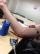
- EMG (Electromyography) Sensor used to control the movement of the wrist
- Most of our parts are off the shelf products to keep the budget low, while still keeping the form factor of the prosthetic arm
[/av_icon_box]
[av_heading tag=’h1′ padding=’10’ heading=’System Design’ color=” style=’blockquote modern-quote’ custom_font=” size=’20’ subheading_active=’subheading_below’ subheading_size=’15’ custom_class=”]
By Mission, Systems, and Test Engineer | Phuong Tran
[/av_heading]
[av_toggle_container initial=’0′ mode=’accordion’ sort=”]
[av_toggle title=’System Design: Mechanical Perspective’ tags=”]

Gray: Humeral Suspension Cuff
Red: Upper Forearm
Yellow: Lower Forearm
Green: Wrist
[/av_toggle]
[av_toggle title=’System Design: Electrical Perspective’ tags=”]

[/av_toggle]
[/av_toggle_container]
[av_hr class=’invisible’ height=’20’ shadow=’no-shadow’ position=’center’ custom_border=’av-border-thin’ custom_width=’50px’ custom_border_color=” custom_margin_top=’30px’ custom_margin_bottom=’30px’ icon_select=’yes’ custom_icon_color=” icon=’ue808′ font=’entypo-fontello’]
[av_icon_box position=’left’ boxed=” icon=’ue820′ font=’entypo-fontello’ title=’System Interface’ link=” linktarget=” linkelement=” font_color=” custom_title=” custom_content=” color=” custom_bg=” custom_font=” custom_border=”]
Link to Interface Definitions:
Prosthetic Arm Interface Definitions
Link to Interface Control Document:
Prosthetic Arm Interface Control Document
Cable Tree:

Link to Mission Command & Control:
Prosthetic Arm Mission Command & Control
[/av_icon_box]
[av_heading tag=’h1′ padding=’10’ heading=’Electronics Design’ color=” style=’blockquote modern-quote’ custom_font=” size=’20’ subheading_active=’subheading_below’ subheading_size=’15’ custom_class=”]
By Electronics and Control Engineer | Mikael Movsisyan
[/av_heading]
[av_tab_container position=’top_tab’ boxed=’border_tabs’ initial=’1′]
[av_tab title=’Buck Converter’ icon_select=’yes’ icon=’ue856′ font=’entypo-fontello’]

[/av_tab]
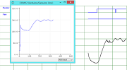
[av_tab title=’LTSpice Simulation Buck Converter’ icon_select=’yes’ icon=’ue858′ font=’entypo-fontello’]

[/av_tab]
[/av_tab_container]
[av_hr class=’invisible’ height=’20’ shadow=’no-shadow’ position=’center’ custom_border=’av-border-thin’ custom_width=’50px’ custom_border_color=” custom_margin_top=’30px’ custom_margin_bottom=’30px’ icon_select=’yes’ custom_icon_color=” icon=’ue808′ font=’entypo-fontello’]
[av_icon_box position=’left’ boxed=” icon=’ue856′ font=’entypo-fontello’ title=’Electronics Custom Parts’ link=” linktarget=” linkelement=” font_color=” custom_title=” custom_content=” color=” custom_bg=” custom_font=” custom_border=”]
LT3971-5 Buck Converter from Linear Technology
Purpose:
- To satisfy L2.2.1 – Wrist Motion
- To step down 11.1V to 5V
Rationale:
- Running current MG996R: 500-900mA (from datasheet)
- Arduino Micro 5V pin rated 200mA
- VCC fluctuations (Appendix 1.)
- Voltage regulators (LM7805) tend to overheat
Reason for specified IC:
- Relatively cheap
- >1V logic (Enable Pin)
- LTSpice simulation showed constant 5V output up to 1.2A
TI’s LM34 Temperature Sensor
Purpose:
- To satisfy L2.4.1 Safety – Temperature
- Measure analog temperature proportional to Fahrenheit
Rationale:
- Above threshold analog input from sensor will cause MCU to power-down
Reason for specified IC:
- Can measure required temperature 50oC i.e. 122F (Appendix 4)
- Used through-hole component in 370L
- Ease of use
GRS-4011 Switch
Purpose:
- To satisfy L2.4.2 Safety – Kill Switch
- Switch off supply to MCU (Appendix??)
Rationale:
- User can manually shut-down prosthetic arm
Reason for specified component:
- Available at hand
- Current/Voltage rating 16A/125V
Sparkfun’s 2 DOF IMU with ADXL203 Accelerometer
Purpose:
- To satisfy requirement from Con Ops
- To measure orientation
Rationale:
- Wrist can only turn in specified orientation (Appendix 3)
Reason for component:
- Available in inventory
- Analog outputEase of use
TowerPro MG996R Servo
Purpose:
- To satisfy L2.2.2. Motion
Reason for component:
- Trade-off-Study
- Load Test
[/av_icon_box]
[av_tab_container position=’top_tab’ boxed=’border_tabs’ initial=’1′]
[av_tab title=’Firmware: Main Program’ icon_select=’yes’ icon=’ue86b’ font=’entypo-fontello’]

[/av_tab]
[av_tab title=’Firmware Flow Chart’ icon_select=’yes’ icon=’ue810′ font=’entypo-fontello’]

[/av_tab]
[av_tab title=’FSM States Overview’ icon_select=’yes’ icon=’ue857′ font=’entypo-fontello’]

[/av_tab]
[av_tab title=’Sleep Interrupt Firmware’ icon_select=’yes’ icon=’ue86b’ font=’entypo-fontello’]


[/av_tab]
[av_tab title=’Sleep Interrupt Flow Chart’ icon_select=’yes’ icon=’ue810′ font=’entypo-fontello’]

[/av_tab]
[/av_tab_container]
[av_hr class=’invisible’ height=’20’ shadow=’no-shadow’ position=’center’ custom_border=’av-border-thin’ custom_width=’50px’ custom_border_color=” custom_margin_top=’30px’ custom_margin_bottom=’30px’ icon_select=’yes’ custom_icon_color=” icon=’ue808′ font=’entypo-fontello’]
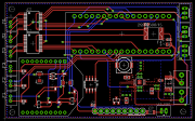
[av_icon_box position=’left’ boxed=” icon=’ue857′ font=’entypo-fontello’ title=’PCB Schematic’ link=” linktarget=” linkelement=” font_color=” custom_title=” custom_content=” color=” custom_bg=” custom_font=” custom_border=”]
Original Design Components
- Arduino Micro
- LM34 Temperature Sensor
- MyoWare EMG Sensor
Unspecified components
- Servo
- Switch
- LiPo Battery
Added Components
- Buck Converter
- IMU
[/av_icon_box]
[av_toggle_container initial=’0′ mode=’accordion’ sort=”]
[av_toggle title=’Prosthetic Arm Fritzing Diagram’ tags=”]

[/av_toggle]
[/av_toggle_container]
[av_hr class=’invisible’ height=’20’ shadow=’no-shadow’ position=’center’ custom_border=’av-border-thin’ custom_width=’50px’ custom_border_color=” custom_margin_top=’30px’ custom_margin_bottom=’30px’ icon_select=’yes’ custom_icon_color=” icon=’ue808′ font=’entypo-fontello’]
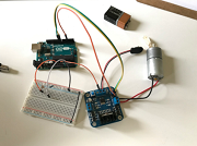
[av_icon_box position=’left’ boxed=” icon=’ue810′ font=’entypo-fontello’ title=’Breadboard Model’ link=” linktarget=” linkelement=” font_color=” custom_title=” custom_content=” color=” custom_bg=” custom_font=” custom_border=”]
- Rapid prototyped 3D design
- MyoWare EMG sensor & IMU analog readings are used to control servo
- Light-dependent voltage divider simulates analog reading from a temperature sensor. Used with sleep ISR to power-down MCU.
[/av_icon_box]
[av_toggle_container initial=’0′ mode=’accordion’ sort=”]
[av_toggle title=’Rapid Prototype Breadboard Layout’ tags=”]

[/av_toggle]
[av_toggle title=’Eagle CAD Schematic’ tags=”]

[/av_toggle]
[av_toggle title=’PCB Layout’ tags=”][/av_toggle]
[/av_toggle_container]
[av_hr class=’invisible’ height=’20’ shadow=’no-shadow’ position=’center’ custom_border=’av-border-thin’ custom_width=’50px’ custom_border_color=” custom_margin_top=’30px’ custom_margin_bottom=’30px’ icon_select=’yes’ custom_icon_color=” icon=’ue808′ font=’entypo-fontello’]
[av_heading tag=’h1′ padding=’10’ heading=’Hardware Design’ color=” style=’blockquote modern-quote’ custom_font=” size=’20’ subheading_active=” subheading_size=’15’ custom_class=”][/av_heading]
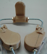
[av_icon_box position=’left’ boxed=” icon=’ue822′ font=’entypo-fontello’ title=’Attachment Module’ link=” linktarget=” linkelement=” font_color=” custom_title=” custom_content=” color=” custom_bg=” custom_font=” custom_border=”]
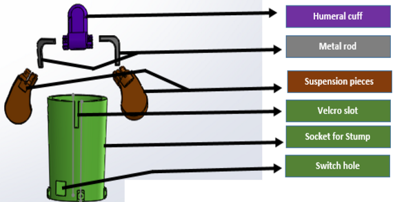
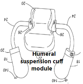
In order to meet the following requirement
- L1-1 – Attachment
- L2-1-Mass Management
- L2-1-2- over shoulder strap
The module shown in figure below was created and modeled after the patented humeral cuff displayed below. Most of these parts were designed in solidworks and printed out. However the ¼ metal rods for the humeral cuff were purchased.
[/av_icon_box]
[av_toggle_container initial=’0′ mode=’accordion’ sort=”]
[av_toggle title=’Solidworks Annotated 3D Exploded View’ tags=”]

[/av_toggle]
[av_toggle title=’Solidworks Annotated Attachment Module’ tags=”]
[/av_toggle]
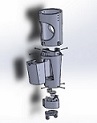
[av_toggle title=’Humeral Suspension Cuff Module’ tags=”]
[/av_toggle]
[av_toggle title=’Humeral Suspension Cuff Mounted on Socket’ tags=”]

[/av_toggle]
[av_toggle title=’Cuff Sitting on Humerus Bone’ tags=”]

[/av_toggle]
[/av_toggle_container]
[av_hr class=’invisible’ height=’20’ shadow=’no-shadow’ position=’center’ custom_border=’av-border-thin’ custom_width=’50px’ custom_border_color=” custom_margin_top=’30px’ custom_margin_bottom=’30px’ icon_select=’yes’ custom_icon_color=” icon=’ue808′ font=’entypo-fontello’]
[av_icon_box position=’left’ boxed=” icon=’ue855′ font=’entypo-fontello’ title=’Wrist Rotation Mechanical Design’ link=” linktarget=” linkelement=” font_color=” custom_title=” custom_content=” color=” custom_bg=” custom_font=” custom_border=”]
The rotation of the wrist is controlled by the servo MG996R which was located in the lower arm. The 90 degree turn (L2-2-1 requirement) of the wrist was met by applying the appropriate gear ration of 17/11= 1.55.
Two gears are designed:
- Driven gear with 17 teeth
- Driver gear with 11 teeth
To avoid the prosthetic hand wire bundle hanging out of the arm, a hole was drawn through the driven gear such that the bundle could travel through it.
![]()
[/av_icon_box]
[av_toggle_container initial=’0′ mode=’accordion’ sort=”]
[av_toggle title=’Driven Gear and Driver Gear’ tags=”]

[/av_toggle]
[av_toggle title=’Servo Used’ tags=”]

[/av_toggle]
[av_toggle title=’Cable Tree Hand & Arm Integration’ tags=”]

[/av_toggle]
[/av_toggle_container]
[av_hr class=’invisible’ height=’20’ shadow=’no-shadow’ position=’center’ custom_border=’av-border-thin’ custom_width=’50px’ custom_border_color=” custom_margin_top=’30px’ custom_margin_bottom=’30px’ icon_select=’yes’ custom_icon_color=” icon=’ue808′ font=’entypo-fontello’]
[av_icon_box position=’left’ boxed=” icon=’ue815′ font=’entypo-fontello’ title=’Mechanical Connection’ link=” linktarget=” linkelement=” font_color=” custom_title=” custom_content=” color=” custom_bg=” custom_font=” custom_border=”]
The prosthetic arm was assembled after final printing. This will be done using M3 screw and hex nuts. Hence hex houses were modeled in solidworks to house these nuts. Some of the advantages of these houses are that they:
- Allow assembly with less maneuvering
- Allow for easier disassembly of the parts
- Are a better fastening method
In addition, the the wrist is modeled in a way that allows the prosthetic hand to attach to the prosthetic arm via screws
[/av_icon_box]
[av_toggle_container initial=’0′ mode=’accordion’ sort=”]
[av_toggle title=’Hex Nut House’ tags=”]

[/av_toggle]
[av_toggle title=’Solidworks Final Wrist Design’ tags=”]

[/av_toggle]
[/av_toggle_container]
[av_hr class=’invisible’ height=’20’ shadow=’no-shadow’ position=’center’ custom_border=’av-border-thin’ custom_width=’50px’ custom_border_color=” custom_margin_top=’30px’ custom_margin_bottom=’30px’ icon_select=’yes’ custom_icon_color=” icon=’ue808′ font=’entypo-fontello’]
[av_icon_box position=’left’ boxed=” icon=’ue808′ font=’entypo-fontello’ title=’Verification Tests’ link=” linktarget=” linkelement=” font_color=” custom_title=” custom_content=” color=” custom_bg=” custom_font=” custom_border=”]
by Mission, Systems, and Test Engineer | Phuong Tran
Link to Final Verification Tests for Prosthetic Arm:
Link to V&V Report for Prosthetic Arm:
V&V Report Prosthetic Arm
[/av_icon_box]
[av_heading tag=’h1′ padding=’10’ heading=’System Resource Reports ‘ color=” style=’blockquote modern-quote’ custom_font=” size=’20’ subheading_active=’subheading_below’ subheading_size=’15’ custom_class=”]
by Mission, Systems, and Test Engineer | Phuong Tran
[/av_heading]
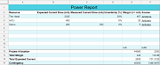
[av_icon_box position=’left’ boxed=” icon=’ue8a9′ font=’entypo-fontello’ title=’Power Allocation’ link=” linktarget=” linkelement=” font_color=” custom_title=” custom_content=” color=” custom_bg=” custom_font=” custom_border=”]

[/av_icon_box]
[av_icon_box position=’left’ boxed=” icon=’ue8d3′ font=’entypo-fontello’ title=’Mass Allocation’ link=” linktarget=” linkelement=” font_color=” custom_title=” custom_content=” color=” custom_bg=” custom_font=” custom_border=”]

[/av_icon_box]
[av_icon_box position=’left’ boxed=” icon=’ue814′ font=’entypo-fontello’ title=’Cost Allocation’ link=” linktarget=” linkelement=” font_color=” custom_title=” custom_content=” color=” custom_bg=” custom_font=” custom_border=”]

[/av_icon_box]
[av_icon_box position=’left’ boxed=” icon=’ue8c5′ font=’entypo-fontello’ title=’Burndown’ link=” linktarget=” linkelement=” font_color=” custom_title=” custom_content=” color=” custom_bg=” custom_font=” custom_border=”]
by Project Manager | Bianca Esquivel

[/av_icon_box]
[av_heading heading=’Project Resources’ tag=’h1′ style=’blockquote modern-quote’ size=’20’ subheading_active=” subheading_size=’15’ padding=’10’ color=” custom_font=”][/av_heading]
[av_textblock size=” font_color=” color=”]
Project Video: Prosthetic Limb 2017 Project Video
CDR PowerPoint: Prosthetic Arm CDR PPT
PDR PowerPoint: Prosthetic Arm PDR PPT
Project Libre & Excel Burndown: Prosthetic Limb Schedule & Burndown
Verification & Validation Report: V&V Prosthetic Arm
Solidworks Files: Mechanical Blog Post 1, Mechanical Blog Post 2, Mechanical Blog Post 3
Eagle CAD Files: Electrical Blog Post
Arduino Code: Software Blog Post
The Entire 400D Prosthetic Limb Folder: Prosthetic Limb 2017 Group Folder
[/av_textblock]