[av_textblock size=” font_color=” color=” av-medium-font-size=” av-small-font-size=” av-mini-font-size=” admin_preview_bg=”]
Simply put, kinematics is the study of motion. Inverse and forward kinematics are mathematical processes used to determine motion and location. For our project we utilized forward and inverse kinematics to accomplish our mission objective. Specifically, it was used to accomplish the second and third steps of Test Plan 3 (TC-3), and requirement 2.1.5.2. These steps of the test plan and the requirement say that the Limbi should be able to move to the second module, and attach to it. Inverse Kinematics was our solution to move Limbi into the module with more precise movements since it allows us to move Limbi straight forward, backwards, left and right as opposed to rotating around a joint.
[/av_textblock]
[av_heading tag=’h5′ padding=’10’ heading=’Basic Kinematics Definitions and Concepts’ color=” style=” custom_font=” size=” subheading_active=” subheading_size=’15’ custom_class=” admin_preview_bg=” av-desktop-hide=” av-medium-hide=” av-small-hide=” av-mini-hide=” av-medium-font-size-title=” av-small-font-size-title=” av-mini-font-size-title=” av-medium-font-size=” av-small-font-size=” av-mini-font-size=”]
Stuff we will put here woohoo…
[/av_heading]
[av_textblock size=” font_color=” color=” av-medium-font-size=” av-small-font-size=” av-mini-font-size=” admin_preview_bg=”]
Before we get into the mathematics and core concepts of forward and inverse kinematics there are a couple words we must define.
Lets begin with a joint. A joint is an object that is connected to a rigid link. The joint has the ability to allow the link to rotate around it. Joints are also referred to as degrees of freedom (DOF).
Figure 1: Joint with attached link
Many joints joined together by links is called an articulated body. An example of this is the human body. For example, your shoulder (a joint) connects to your upper arm (a link), which connects to your elbow (a joint), which connects to your forearm (a link), and so on. So therefore, your whole body is an articulated body made up of joints and links.
Two other important words we need to learn are root joint and end effector. If we are using the arm as an example again, and if we assume that the rest of your body is in a fixed position and not moving, the shoulder becomes the root joint since it is the root of all movement, and your finger tips become the end effector, or the farthest position of the most outward link.
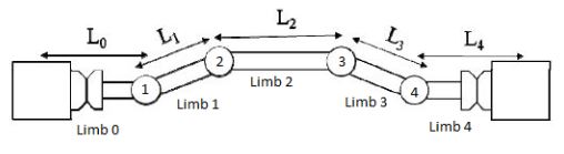
However, using the body as an example becomes very complicated with forward/inverse kinematics because the more degrees of freedom an articulated body has, the more complicated the math becomes. So from this point forward we will be using Limbi as our example. Limbi has 4 DOF, and 5 links. All movement of Limbi is limited to a 2D, X,Y plane. Below is a simplified image of Limbi.
Figure 2 – Limbi
Even though Limbi has 4 DOF, Limbi was split in two sides as can be seen above and the kinematics operations are ever only performed on one side at a time. Lets assume this side is side 1. This causes the forward/inverse kinematics to be on only 2 DOF (Joint 1 and Joint 2). In this case, the root joint becomes Joint 2, and the end effector becomes the end of the most outbound link connected to Joint 1.
[/av_textblock]
[av_heading tag=’h2′ padding=’10’ heading=’Forward Kinematics’ color=” style=” custom_font=” size=” subheading_active=” subheading_size=’15’ custom_class=” admin_preview_bg=” av-desktop-hide=” av-medium-hide=” av-small-hide=” av-mini-hide=” av-medium-font-size-title=” av-small-font-size-title=” av-mini-font-size-title=” av-medium-font-size=” av-small-font-size=” av-mini-font-size=”]
Stuff we will put here woohoo…
[/av_heading]
[av_textblock size=” font_color=” color=” av-medium-font-size=” av-small-font-size=” av-mini-font-size=” admin_preview_bg=”]
Now that we have a basic understanding of the words and definitions used in kinematics, we can begin understanding forward and inverse kinematics.
For our application, forward kinematics is the mathematical process used to determine the position of the end effector. This is done using basic trigonometry, where the angles of the joints and the lengths of the links are used to solve the end effector position.
For our project, since we are using a robot with 2 DOF in the XY plane, we have a set up as the one below.
Figure 3 – Joint Angles and Link Lengths
Where Phi is the angle of our joint 1 (middle joint 1), theta is the angle of joint 2, L1 is the length of the link connected to Joint 2, and L2 is the length of the link connected to Joint 1. If we place Limbi in the XY plane, we get what is pictured below in Figure 4. As we can see from below, Joint 2 will always be placed at the point (0,0), and is our point of reference. From that point, using forward kinematics, we can determine an XY position for the end effector.
Figure 4 – End Effector Position
Using forward kinematics we get the two equations below:
These two equations give us the end effector position using the angles and lengths of our structure.
[/av_textblock]
[av_heading tag=’h2′ padding=’10’ heading=’Inverse Kinematics’ color=” style=” custom_font=” size=” subheading_active=” subheading_size=’15’ custom_class=” admin_preview_bg=” av-desktop-hide=” av-medium-hide=” av-small-hide=” av-mini-hide=” av-medium-font-size-title=” av-small-font-size-title=” av-mini-font-size-title=” av-medium-font-size=” av-small-font-size=” av-mini-font-size=”]
Stuff we will put here woohoo…
[/av_heading]
[av_textblock size=” font_color=” color=” av-medium-font-size=” av-small-font-size=” av-mini-font-size=” admin_preview_bg=”]
Finally, after all the reading and investigating we can finally jump into the interesting and useful stuff—Inverse Kinematics. Inverse kinematics is exactly the opposite of forward kinematics. In inverse kinematics we have a desired X and Y position for the end effector, and using the given lengths of the links we find the angles of each joint necessary to achieve that positioning.
This type of mathematics is very useful, but also complicated. In forward kinematics, the process was very simple because there will ever only be one answer. However, in inverse kinematics there can be multiple solutions to one problem or there could even be no solution if the desired point is out of the reach of the links.
Inverse kinematics is out of the scope of this class, but I can provide you with the equations that we used for Limbi.
In these equations, x and y are the desired coordinates. Phi is the angle calculated for Joint 2 and Theta is the angle calculated for Joint 1.
[/av_textblock]
[av_textblock size=” font_color=” color=” av-medium-font-size=” av-small-font-size=” av-mini-font-size=” admin_preview_bg=”]
Inverse kinematics and forward kinematics are very useful types of math with many applications, however the complexity of the kinematics equations depends on a case to case basis. The first resource I have linked proved to be very useful for me and even contains an excel spreadsheet that can help you simulate forward and inverse kinematics. If you are interested in this subject I would recommend doing further research as well as reading the first reference I linked.
[/av_textblock]
[av_heading tag=’h2′ padding=’10’ heading=’Program and Project Objectives’ color=” style=” custom_font=” size=” subheading_active=” subheading_size=’15’ custom_class=” admin_preview_bg=” av-desktop-hide=” av-medium-hide=” av-small-hide=” av-mini-hide=” av-medium-font-size-title=” av-small-font-size-title=” av-mini-font-size-title=” av-medium-font-size=” av-small-font-size=” av-mini-font-size=”]
Stuff we will put here woohoo…
[/av_heading]
[av_textblock size=” font_color=” color=” av-medium-font-size=” av-small-font-size=” av-mini-font-size=” admin_preview_bg=”] Program Objectives
The idea of Limbi is to be a crawling robotic space limb that would fix and/or maintain spacecraft to reduce (or eliminate) the need for astronauts to have tethered spacewalks to do such tasks. Another foreseeable future of Limbi is to act as a reconfigurable robots called limboids (smaller limbis) to build unique space structures.
JPL designed a prototype that uses electromagnets for the docking mechanism which draws huge amounts of current. Our team’s contribution to the advancement of Limbi is the development of a low-power momentumless mechanical docking mechanism that is also capable of power transfer.
Project Objectives
Limbi is a Robotic arm that has 4 degrees of freedom (joints), each capable of moving 180 deg on one plane, as well as an end-over-end mobility. Each end of the arm is androgynous (universal connector for both arm-to-module and module-to-module interconnects) connector capable of mating with an identical pair. Part of Limbi is the “spacecraft” module that has the same androgynous connector on its faces. Each module is capable of supplying power to the arm.
[/av_textblock]
[av_textblock size=” font_color=” color=” av-medium-font-size=” av-small-font-size=” av-mini-font-size=” admin_preview_bg=”] The objective of Limbi is to connect two “spacecraft” modules into a specified position using the Arxterra App to demonstrate in-space assembly. At the start of phase 0 one end of the arm will start connected to Module 1 which will supply power to the arm. Module 1 is in a fixed position. For phase 1 the other end of the arm will grab module 2 through the docking mechanism. At this point, both modules are both supplying power to the arm (make-before-break circuitry). During phase 2 the arm will bring module 2 and connect it to module 1 through the module-to-module faces of both modules. During phase 3 the arm will undock from module 1 and module 2 will solely supply power to the arm for missions success. These phases can be found below in Figure 1.
A more detailed description can be found here.
[/av_textblock]
[av_textblock size=” font_color=” color=” av-medium-font-size=” av-small-font-size=” av-mini-font-size=” admin_preview_bg=”] The goal of Limbi is to demonstrate in-space assembly that has a low-power momentumless mechanical docking mechanism with positive lock while having a continuous power supply from the module(s). Our team came up with a two layer docking design in the module side and a cross-shaped manipulator in the arm side that will initiate a 3 step sequence to dock: 45 degree turn, power transfer, and a actuate a positive lock.
[/av_textblock]
[av_textblock size=” font_color=” color=” av-medium-font-size=” av-small-font-size=” av-mini-font-size=” admin_preview_bg=”] For the Limbi, requirements were an iterative process; they stemmed from the customer’s expectation, JPL’s model of the Limbi, and the conceptual operation of the final mission. Level 1 requirements are design independent requirements; for Limbi these were separated into requirements for the arm and the module. For the arm these then separated more into General, Mobility, Electronics and Control, and Special Features. These flowed down to Level 2 design dependent requirements which clarified the performance of separate systems and components. All requirements should be quantitative, verifiable, and realizable. To find more information on the creation of the requirements of the Limbi see: Creating Requirements and Servo Test.
[/av_textblock]
Applicable Engineering Standards and Environmental, Health, and Safety (EH&S) Standards
L 1.30 The Limbi shall employ a custom PCB to extend the functions of the arduino nano by allowing control of 6 servos, and logic levels compatible with the hm-11.
L2.1.19.1 The custom PCB will use surface mount technology including the Hm-11 and the SN74LV1T34 Logic Shifter
L 1.31 Disassemble and Reassemble of the robot shall be constrained to less than 20 minutes (10 minutes+10 minutes) (waived)
L 1.32 The Limbi shall be completed by the date of the final: May 14th 2019.
L 1.33 The robot shall be designed in such a way that there are no dangling or exposed wires.
L 1.34 The form factor of Limbi shall be constrained by the original JPL version (see requirement L1.2)
L 1.35 The usability of the Limbi shall be enhanced by use of the Arxterra phone and control panel application
L 2.1.35.1 The ArxRobot app shall allow control of all joint servos and docking servos (see requirement L 1.10)
L 1.36 Back of the envelope calculations and experiments shall be conducted to set the diameter of power carrying wires. Follow the American Wire Gauge (AWG) standard when defining the diameter of power carrying wires.
L 1.37 Manufacturability of 3D printed robots shall minimize the number of files to be printed when using the library’s Innovation Space to print the final robot (waived)
Out of the standards, codes, and regulations as defined in the “Engineering Standards and Constraints” Section, these are the ones that apply to Limbi
L 1.38 All Lithium (Li-ion, Li-polymer) batteries shall be stored, when not in use, in a fire and explosion proof battery bag.
L 1.39 Software shall be written in the Arduino De facto Standard scripting language and/or using the GCC C++ programming language, which is implements the ISO C++ standard (ISO/IEC 14882:1998) published in 1998, and the 2011 and 2014 revisions.
L 1.40 The Limbi shall be controlled via Bluetooth 4.0 in compliance with the Bluetooth Special Interest Group (SIG) Standard (supersedes IEEE 802.15.1).
[/av_textblock]
[av_textblock size=” font_color=” color=” av-medium-font-size=” av-small-font-size=” av-mini-font-size=” admin_preview_bg=”] For Limbi the project unique functional requirements related to the form factor of the JPL Limbi and the fact that conceptually Limbi is meant to be used in space. This led to requirements related to end-over-end mobility, and docking mechanisms that could be implemented without pushing force.
[/av_textblock]
L1.1 Objective shall be demonstrated on a low friction surface
L 1.2 The Limbi project will be smaller than the JPL Limbi for cost and storage purposes.
Mobility:
L 1.3 The arm’s 4 joints shall move 4 of the 5 limbs (see Figure 2).
L 1.4 Each joint shall have 180 degrees of movement in one plane (x-y).
L 1.5 The arm shall be able to connect and disconnect with the modules
L 1.6 Docking mechanism shall keep the arm and module connected as the arm moves until it is meant to be disengaged.
L 1.7 The arm shall have a docking mechanism on each end to connect to two modules at once.
L 1.8 The arm shall be able to move module (in the same plane as the actuator planar scope).
L 1.9 The arm shall be able to link two modules together via permanent magnets.
Electronics and Control
L 1.10 The movement of the arm shall be controlled by the user with custom software.
L1.11 The Limbi shall be controlled with a microcontroller
Special Features
L 1.12 The arm should provide live video feed capability.
Requirements (Module):
L 1.13 Each module shall have the capability of providing power to the arm.
L 1.14 The arm shall only be powered with one power source (for extended amounts of time)
L 1.15 For demonstration purposes the module shall have docks on only 2 out of 6 faces
L 1.16 The module should indicate when secure connection is made between the Limbi and modules with an LED.
L 1.17 One module shall be defined as the base module and shall be stationary to represent a large, unmoving mass in space (such as the spacecraft). This requirement is based on Section 4 of “An Untethered Mobile Limb for Modular In-Space Assembly”.
[/av_textblock]
[av_textblock size=” font_color=” color=” av-medium-font-size=” av-small-font-size=” av-mini-font-size=” admin_preview_bg=”] Our Level 2 requirements flow from our Level 1 requirements. They expand on performance specifications that allow the Level 1 requirements to be accomplished. Limbi’s Level 2 requirements include values such as servo, battery, and magnet specifications, size constraints, and how specific components will interact with each other.
[/av_textblock]
[av_textblock size=” font_color=” color=” av-medium-font-size=” av-small-font-size=” av-mini-font-size=” admin_preview_bg=”] L2.1.1.1 The arm will be supported with metallic ball casters on Limb 0 and Limb 4 to simulate the conditions where the arm will not be affected by gravity.
L 2.1.2.1 The Limbi will follow the form factor of the JPL version; the lengths will be optimized in respect to inverse kinematics
L 2.1.3.1 Joint 1 shall control the motion between Limb 0 and Limb 1.
L 2.1.3.2 Joint 2 shall control the motion of between Limb 1 and Limb 2.
L 2.1.3.3 Joint 3 shall control the motion between Limb 2 and Limb 3.
L 2.1.3.4 Joint 4 shall control the movement between Limb 3 and Limb 4.
L 2.1.4.1 The Limbi will have 4 joints controlled by servos.
L 2.1.4.2 Each servo shall require no more than 7.4V and 500mA to run with a load
L 2.1.4.3 The servo shall be able to provide more than .237 Nm or 2.417kg/cm based on the force to move an object in a planar field
L 2.1.5.1 The docking mechanism shall consist of the interlocking mechanical device described in requirement L2.1.8.1 that allows the Limbi arm to successfully attach and detach to and from the module
L 2.1.5.2 The arm shall be able to attach and detach to and from a module without pushing the module away.
L 2.1.5.3 The module should have an androgynous connector.
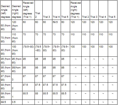
L2.1.6.1 The slot for the cross shall be at least 1.52 mm larger than the cross based on the max vernier servo error of 1 degree.
L2.1.10.1 The custom software will be implemented through the Arxterra App
L2.1.10.2 The user interface shall utilize wireless control of Limbi.
L2.1.10.3 The user interface shall have push buttons/toggles for pre-determined movements
L2.1.10.4 The user interface shall use simulated sliders for manual movements.
L2.1.11.1 The project will use an Arduino Nano mounted within the Limbi arm to allow the servos to be controlled directly by the microcontroller
L2.1.12.1 A TTL Serial Camera and TFT LCD display should be used to provide live video feed for alignment.
L2.1.13.1 The power provided from the module shall come from a battery via the docking mechanism
L2.1.13.2 The battery shall be capable of providing 1055 mA current (if needed) which will be used to power the MCU, 6 servos, Bluetooth Module, TFT LCD Display, and TTL Serial Camera.
[av_textblock size=” font_color=” color=” av-medium-font-size=” av-small-font-size=” av-mini-font-size=” admin_preview_bg=”] The mass allocation came from a rough estimate of the weight of our Limbi compared to the JPL version. We did not know the weight of the JPL version, but we did know that they required 80lb pull force magnets to connect the module to the arm; this gave us the idea that the arm weighed roughly 80lbs. Knowing that our Limbi would be half the size and made out of ABS plastic we allocated 5lbs to the project. The measured weights of Limbi were much less because the Limbi was printed in PLA. We largely overestimated the weight of the magnets, causing the docking mechanisms to weight more than the modules; this was corrected in the actual measurements and in reality the modules weight more than the docking mechanism. Our contingency is high to allow the Limbi arm and modules to be printed out of different materials.
[/av_textblock]
[av_textblock size=” font_color=” color=” av-medium-font-size=” av-small-font-size=” av-mini-font-size=” admin_preview_bg=”] The power allocation came from the estimate of the amount of current draw our servos would need. We knew that the servos would draw the most power and that we would have 6 servos. Estimating that each servo would need about 250A we decided on a battery that would provide 1500mAh. This provided the allocation for the battery which we used for the whole project. When we actually decided on parts we realized that the servos could draw a max of approximately 300mA each, but only 3 servos needed to be used at once since only one side of the arm would be used at once and one docking mechanism would be used at once. For our expected values we had large uncertainty because we didn’t know how the load would affect the current draw, this resulted in large margin. For contingency we were trying to plan for the worst case scenario and found that if all parts ended up being over the expected values that we would still have room left from our allocated amount of 1500mAh. This gave us leeway in how much we could add in terms of electronics and how long our battery would be able to run. For our actual measured values we ended up getting significantly lower current draw than expected from the servo, but we added an solenoid that draws significantly high current for a very short amount of time which caused us to use more than our expected current.
[/av_textblock]
Limbi’s Work Breakdown Structure is divided into three parts: Missions Systems and Test, Electronics and Control and Design and Manufacturing.
Missions Systems and Test is responsible for the System Requirement, Project Allocation, and Verification/Validation of tests performed by the E&C and D&M.
E&C is responsible for the electrical architecture of the arm and module, the power transfer design innovation and the PCB layout,
D&M is responsible for the arm, module mechanical design and the momentumless low-power mechanical docking mechanism design.
ADD DESCRIPTION
Figure 3: WBS
PBS:
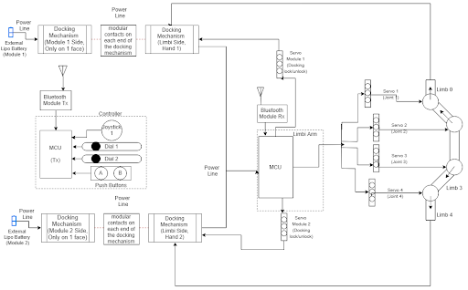
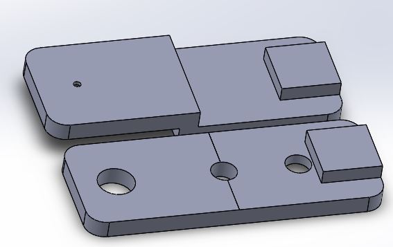
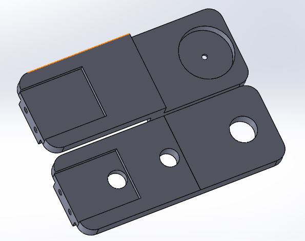
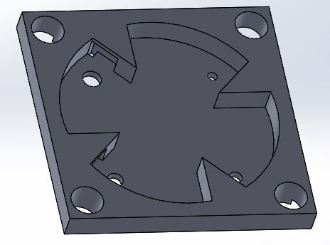
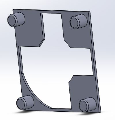
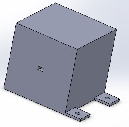
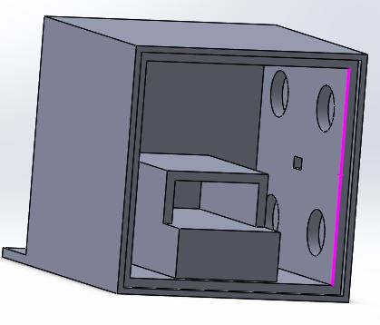
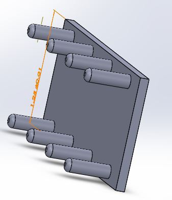
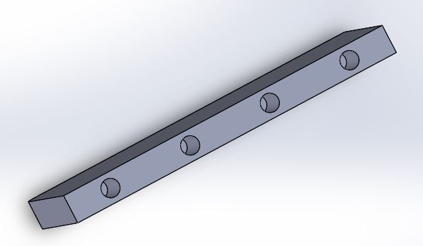
The Limbi project breaks down into three separate components. It consists of the Limbi arm, the base module (Module 1), and the second module (Module 2). The arm further breaks down into 5 limb segments which are controlled by 4 joints, docking mechanisms on either end of the arm, and a power distribution system, communication system, and control system. The power control system, communication system, and control system are all implemented through the Arduino Nano, Hm-11, and a custom PCB and is located in the center of the Limbi arm. The docking mechanism is what interfaces the arm and the module. The docking mechanism on the arm connects to the docking mechanism on the module; this connection provides power from the battery in the modules to the power control system, communication system, and control system. Each module is identical and they both contain a battery and two docking faces; one face is a module-to-arm face (which provides power) and one is a module-to-module face (which connects the two modules to each other). This is shown below in Figure 6.
[av_textblock size=” font_color=” color=” av-medium-font-size=” av-small-font-size=” av-mini-font-size=” admin_preview_bg=”]
For the cost we did not have a project allocation of $250 because we are not a 3DoT project. Our allocation was determined at CDR based on how much we had spent, but even with our contingency and margin, we ended up going over budget due to final design changes and extra print versions that we did not account for. Our main suppliers were Amazon and Mouser Electronics. We went through many suppliers and compared the costs, but chose to use Amazon mainly because the lack of shipping cost we achieved through using a Prime account lowered the cost compared to buying from separate suppliers.
The total cost for the Limbi Spring ’19 project is about 400$.
[av_textblock size=” font_color=” color=” av-medium-font-size=” av-small-font-size=” av-mini-font-size=” admin_preview_bg=”]
The project manager of the team have decided to use excel spreadsheet for the schedule burndown instead of targetprocess in which the whole team agreed on. The excel spreadsheet captures both action items and schedule breakdown in one whole matrix. Each task has 8 columns: description, priority (High, Medium, Low), assigned to (person responsible), status (open, percentage complete, pending, close), hours spent, expected and completed date, and comment. This way, we can easily keep track of what is holding the design process from moving forward.
[av_textblock size=” font_color=” color=” av-medium-font-size=” av-small-font-size=” av-mini-font-size=” admin_preview_bg=”]
We had three main literature resources for this project: JPL’s Limbi IEEE paper, and the previous Arxterra documentation for Research and the PDR.
The previous Arxterra PDR documentation consists of a project proposal for an interdepartmental project to improve the Limbi for use by JPL. It was proposed as a two semester senior design project, that would be a collaboration on work done by the MAE,CECS, and EE departments. The post laid out a potential schedule for the two semester course. The previous CSULB Mission Objective was to contribute to the advancement of the Limbi by adding mechanical interconnects for docking, and improving the power transfer.
The research overviewed the goal of the Limbi, the current design, and the power module design. Some key points it made were:
The goal of the Limbi is to create a multi-jointed, autonomous robot that can reconfigure itself, and attach itself to other limbiods to construct spacecrafts or fix space structures.
The current design is a JPL prototype that attaches itself to makeshift spacecraft modules and arranges them into a given position.
This design uses cube-shaped power modules where one of the modules provides power to all other modules and to the detachable Limbi arm.
The current docking mechanism utilizes electromagnets; however, this limits the rigidity of the modules.
The JPL Paper, “An Untethered Mobile Limbi for Modular In-Space Assembly” goes into detail about the current Limbi and the future of the Limbi. For the JPL mission objective it was to develop autonomous reconfigurable robots that can assemble and fix large space structures and spacecraft. The current JPL Limbi is not autonomous, but completes its mission using predefined movements. The JPL Limbi acts only on one plane and uses rotary actuators to control its movements. Other key factors that were discussed in this paper were the limb design dimensions, the symmetry of the arm, and the proportions of the limb segments which had small vernier segments and a large center segment. Unfortunately, JPL used electromagnets as the primary docking mechanism which was incredibly inefficient in terms of power use, and also the electromagnet strength drops rapidly with small distances, making the mechanism prone to failure from high moments.
We used information from these three sources to imitate the Limbi design and improve it. Based on the information gathered from our literature review we decided against the use of electromagnets (at the cost of no longer having androgynous docking), replaced the docking mechanism with a mechanical interlocking, low momentum option, and kept the form factor of the Limbi only modifying the arm proportions for the use of inverse kinematics.
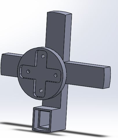
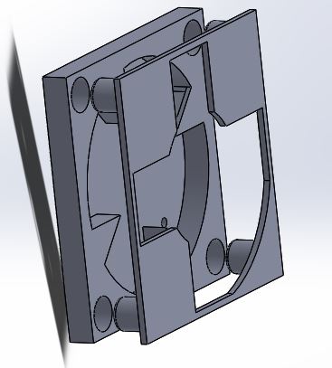
Docking Mechanism – Momentumless docking mechanism for arm-to-module connection that is also compatible for module-to-module connection. Docking Design
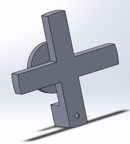
For the arm-to-module connection we used a momentumless docking mechanism. On the arm side, this mechanism includes a cross and a push-pull solenoid for auto lock. On the module side, the docking mechanism has two layers; the bottom layer is recessed and allows for the cross to be turned and the top layer covers the recessed part of the bottom layer so the cross can’t fall out. When the docking mechanism is in use the first stage includes the cross turning 45° and once in place the second stage of docking is the solenoid inserting into a fixed position (this is powerless). To undock, power must be applied to the solenoid to retract it and then the cross turns 45° counter-clockwise to complete undocking.
Make-Before-Break Power Transfer – Continuous power supply to the arm pre, post and during module change.
Power Transfer
To provide continuous power to the arm a make-before-break circuit was used. The cross represents the switch in the make-before-break circuit. In a make-before-break circuit it allows both batteries to power the arm before disconnecting from the original battery. This method was used to prevent the microcontroller from disconnecting between transfer from Module 1 to Module 2.
Docking-Power Transfer Interface – Interface between the docking mechanism and power supply.
For power transfer between the modules and the arm male modular contacts and copper tape were used. On the module side the battery is connected to the male modular contacts. The copper tape is located on the cross and provides power to the circuitry located on the arm; when the cross is docked the copper tape touches the male modular contacts which allows power to transfer between the battery in the module and the circuitry on the arm.
[/av_textblock]
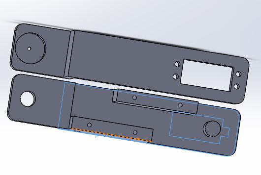
[av_textblock size=” font_color=” color=” av-medium-font-size=” av-small-font-size=” av-mini-font-size=” admin_preview_bg=”] Our team came up with a two layer docking design in the module side and a cross-shaped manipulator in the arm side that will initiate a 3 step sequence to dock: 45 degree turn for the cross, power transfer (or signal line for feedback) through the modular contact, and a actuate a normally open (lock position) push-pull solenoid valve for low power positive lock.
*picture of the actual design together
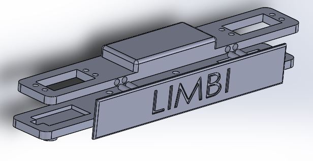
Figure 8: Exploded view of 3D Model
[/av_textblock]
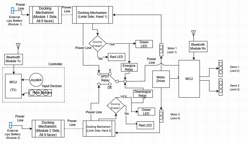
The system block diagram shows how different components of the Limbi interface with each other. The power starts with the battery in Module 1 and powers the components within the Limbi arm through the docking mechanisms on the module and the arm. This power is then distributed to the Arduino and an external Buck Converter which distributes the power appropriately. The Custom PCB powers the servos and the Arduino sends commands to the servos using the Hm-11. The Hm-11 communicates with the Arxterra app and this then controls the servos which move the arm segments. A make before break system is set up so the arm connects to Module 2 and secures power before undocking from Module 1. This allows the Limbi arm to move from end to end while maintaining consistent power from one module or the other.
[av_textblock size=” font_color=” color=” av-medium-font-size=” av-small-font-size=” av-mini-font-size=” admin_preview_bg=”]
For interface we have the interface matrix which shows connections between the Arduino Nano, Custom PBC, and components. This can be found in Figure below.
Table 5: Interface Matrix
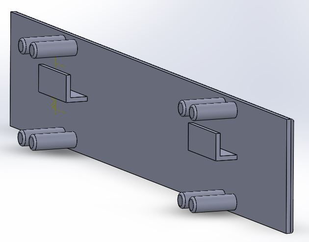
Below is the cable tree which shows how the wires will be routed through the Limbi. Power between the batteries within the modules and the cross will be transferred between aluminum and male modular contacts. (No wires will directly connect the module and arm). The cross will have grooves routed through the back to allow the wires to travel through, the wires will use a wire wrap around the connection of the cross to prevent them from tugging. The module wiring harness will consist of only the power and ground which will be connected to aluminum. The servo power wires will be connected to the custom PCB using JST connectors. The servos will implement keyed 3 pin molex connectors. The power wires will be connected to the arduino and the DC/DC buck converter. The buck converter will provide power to the PCB. The wires will be routed through the center of either side of the blue braces shown in the picture below.
[av_textblock size=” font_color=” color=” av-medium-font-size=” av-small-font-size=” av-mini-font-size=” admin_preview_bg=”]
The following are the experiments performed to tests design concepts:
Magnet Test
Objective: To test if the magnets are strong enough to dock but weak enough to not cause stalled joint servos to rotate. Magnets Test
Press Fit Test
Objective: To test tolerance to implement press fit design. Press fit Test
Inverse Kinematics Test
Objective: To test code for a forward motion to align cross for docking. Inverse Kinematics Test
Docking-Power Transfer Interface Test
Objective: To test continuity and resistance changes of the docking-power transfer interface design while the arm is moving the module. Docking Video Continuity Test
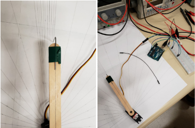
Servo Error Test
Objective: To the test the minimum servo rotation for our Vernier limb (L0 and L4) to calculate the slot tolerance for docking layer 2. Servo Error Test
The Limbi will be mainly controlled through the Arxterra App or Control Panel. All the control commands are custom commands, that are explained more in depth in the separate Firmware Blog Post. The custom commands that are used to control the Limbi are shown in the figure above. Below is a brief overview of the command, it’s address, and a general description.
MOVE (0x01) – The move command has been modified to control the middle and end servos (on either side), and performs inverse kinematics to move the Limbi forwards, backwards, left or right.
DOCK 1 (0x40) – The Dock 1 custom command is an ON/OFF button that docks and undocks the Limbi on side 1 of the Limbi.
DOCK 2 (0x41) – The Dock 2 custom command is an ON/OFF button docks and undocks the Limbi on side 2 of the Limbi
VERNIER CONTROL 1 (0x42) – The Vernier Control 1 custom command is a slider with values between 1 and 180, and it writes an angle to the vernier control on side 1 of the limbi
VERNIER CONTROL 2 (0x43) – The Vernier Control 2 custom command is a slider with values between 1 and 180, and it writes an angle to the vernier control on side 2 of the limbi
MIDDLE CONTROL 1 (0x44) – The Middle Control 1 custom command is a slider with values between 1 and 180, and it writes an angle to the middle joint on side 1 of the limbi
MIDDLE CONTROL2 (0x45) – The Middle Control 2 custom command is a slider with values between 1 and 180, and it writes an angle to the middle joint on side 2 of the limbi
INVERSE KINEMATICS (0x46) – The Inverse Kinematics custom command is a select with two options (END 1 and END 2). Selecting either end will determine what end the inverse kinematics will be performed on.
[av_textblock size=” font_color=” color=” av-medium-font-size=” av-small-font-size=” av-mini-font-size=” admin_preview_bg=”]
Our E&C team went through quite a few design iteration for the PCB and the firmware to meet design requirement and specification.
[/av_textblock]
[av_textblock size=” font_color=” color=” av-medium-font-size=” av-small-font-size=” av-mini-font-size=” admin_preview_bg=”] We decided to make use of the Arduino Nano microcontroller due to its small scale and ease of integration with a custom PCB shield that would allow a better organization of wires in a small enclosed space located within the center limb of the arm.
The servos utilized were rated to operate at a maximum of 6V so we needed to implement a DC-DC buck down converter to drop the voltage down from the 7.4V Lipo Batteries we would be using. This means the board would have an input of 7.4V directly from the battery to power the MCU, a 6V to feed towards the servos, and naturally a GND. To serve as protection from potential short circuit dangers, 4.5A polyfuses were used on the power lines.
In addition to servo control, a solenoid valve would also need to be controlled as a positive locking mechanism at each end of the arm for docking. Since the solenoid pin was able to be compressed on its spring with very low amount of force the design was implemented in a way such that the solenoid would only need to be actively powered during the undocking phase in which it should retract thus allowing for free rotation of the docking servo. To achieve this a simple MOSFET switching circuit was implemented which allowed for the solenoid to be powered by the 6V line when the digital output D12 from the MCU applied voltage on the gate of the MOSFET. In addition to this a diode was connected between both solenoid lines which would prevent current discharging backwards when the solenoid coil disharged. Naturally this circuit was implemented symmetrically for both sides.
To facilitate wireless communication between the operating application and the arm an HM-11 BLE module was utilized. The bluetooth module requires a 3.3V power supply which is provided by the MCU 3.3V output. Since the MCU operated on a 5V logic and the HM-11 3.3V logic, translation between the devices was necessary. This was achieved through utilizing single buffer gate logic level shifters. These IC’s functioned to provide up and down translation based on the power supplied to them. So for instance the Tx pin on the MCU operates at a 5V logic level, by providing the buffer with a 3.3V power supply from the MCU, the logic is translated to a 3.3V level that can be properly interpreted by the HM-11 module, and vice-versa.
The schematic can be seen below:
Figure 12: PCB Schematic
The general design philosophy behind the board would be to have a symmetric output headers on the left and right side which would provide power and control signals to the 3 servos and locking solenoid on each side of the arm. At the top of the board would be the inputs for the direct battery, as well as the regulated 6V output from the buck converters. All components on the board were SMD with the exception of the diodes. Finally all four corners of the board contain screw holes to mount on the arm. The component list and board layout can be seen below, as well as a picture of the final assembled version and the buck converter used.
[av_textblock size=” font_color=” color=” av-medium-font-size=” av-small-font-size=” av-mini-font-size=” admin_preview_bg=”]
Before I begin explaining the firmware, and how it controls each joint, I believe it is important for the reader to grasp how the Limbi looks, and the name of each joint. This will help the reader understand what I’m referring to in the rest of this section.
Limbi 2DAs seen in the Figure above, the Limbi has 4 joints. In this report, I will be referring to Joint 1 as Vernier Control 1, Joint 2 as Middle Control 1, Joint 3 as Middle Control 2, and Joint 4 as Vernier Control 2.
The firmware for our project contains 7 custom commands, and 1 command redefinition. These custom commands are: Move, Dock 1, Dock 2, Vernier Control 1, Vernier Control 2, Middle Control 1, Middle Control 2, and Inverse Kinematics Selector. These are briefly described in the Mission Command and Control Section above.
Below is the most recent code for Limbi.
#define DOCK1 0x40 // Dock 1 Custom Command Address#define DOCK2 0x41 // Dock 2 Custom Command Address#define VERNIER1 0x42 // Vernier 1 Custom Command Address#define VERNIER2 0x43 // Vernier 2 Custom Command Address#define MIDDLE1 0X44 // Middle 1 Custom Command Address#define MIDDLE2 0X45 // Middle 2 Custom Command Address#define IKSELECTOR 0x46 // Inverse Kinematics Selector Custom Command Address#define L1 154L // Define the length of length 1 (measurement is in mm) #define L2 125L // Define the length of length 2 (measurement is in mm) const uint8_t CMD_LIST_SIZE = 8; // Adding 8 commands (MOVE, DOCK1, DOCK2, VERNIER1, VERNIER2, MIDDLE1, MIDDLE2, IKSELECTOR)int globalIKSelector = 0;int globalPhi1; // Saves angle last written to mid1 Servo for use in Inverse Kinematicsint globalTheta1; // Saves angle last written to end1 Servo for use in Inverse Kinematicsint globalPhi2; // Saves angle last written to mid2 Servo for use in Inverse Kinematicsint globalTheta2; // Saves angle last written to end2 Servo for use in Inverse Kinematicsint globalCount = 1; // Used for conditional statements to prevent both docks from being undocked at the same time// Create variable speed servo objectsVarSpeedServo mid1; // Joint 2VarSpeedServo mid2; // Joint 3VarSpeedServo end1; // Joint 1VarSpeedServo end2; // Joint 4VarSpeedServo dock1; // Dock 1VarSpeedServo dock2; // Dock 2void dock1Handler (uint8_t cmd, uint8_t param[], uint8_t n){ dock1.attach(2); // Attach dock1 servo to pin 2 if(param[0] == 1 ){ // Using boolean: if button = 1 = ON DOCK TO MODULE dock1.slowmove(41,40); // Move dock 1 Servo to angle of 41 degrees at speed 40/255 delay(2000); // Delay allows servo to get to position before detaching globalCount = 1; // Set Global Count to 1 when Dock 1 is connected } else{ // Else: button = 0 = OFF UNDOCK FROM MODULE if(globalCount%2==0){ // Takes remainder of division globalCount/2, to check if it's // odd or even // If it's even, it allows the dock to be undocked digitalWrite(10,HIGH); // Set's Push Pull Solenoid to High so that it retracts delay(1000); dock1.slowmove(90,40); // Move dock 1 Servo to angle of 90 degrees at speed 40/255 delay(1000); digitalWrite(10,LOW); // Set's Push Pull Solenoid to Low so power is not being drawn delay(500); } } dock1.detach(); // Detach dock1 servo from pin} // dock 1 Handlervoid dock2Handler (uint8_t cmd, uint8_t param[], uint8_t n){ dock2.attach(4); // Attach dock2 servo to pin 4 if(param[0] == 1){ // Using boolean: if button = 1 = ON DOCK TO MODULE dock2.slowmove(41,40); // Move dock 2 Servo to angle of 41 degrees at speed 40/255 delay(2000); // Delay allows servo to get to position before detaching globalCount = 2; // Set Global Count to 2 when Dock 2 is connected } else{ // Else: button = 0 = OFF UNDOCK FROM MODULE if(globalCount%2==1){ // Takes remainder of division globalCount/2 // If it's odd, it allows the dock to be undocked digitalWrite(9,HIGH); // Set's Push Pull Solenoid to High so that it retracts delay(1000); dock2.slowmove(90,40); // Move dock 2 Servo to angle of 90 degrees at speed 40/255 delay(1000); digitalWrite(9,LOW); // Set's Push Pull Solenoid to Low so power is not being drawn delay(500); } } dock2.detach(); // Detach dock2 servo from pin} // dock 2 Handlervoid vernier1Handler (uint8_t cmd, uint8_t param[], uint8_t n)//param[0] = unsigned byte (1-180){ end1.attach(3); // Attach end1 servo to pin 3 end1.slowmove(param[0],40); // Move end1 Servo to angle of param[0] degrees at speed 40/255 delay(2500); end1.detach(); // Detach end1 servo from pin 3 globalTheta1 = param[0]; // Saves end1 servo angle for use in Inverse Kinematics} // vernier 1 Handlervoid vernier2Handler (uint8_t cmd, uint8_t param[], uint8_t n)//param[0] = unsigned byte (1-180){ end2.attach(5); // Attach end2 servo to pin 5 end2.slowmove(param[0],40); // Move end2 Servo to angle of param[0] degrees at speed 40/255 delay(2500); end2.detach(); // Detach end2 servo from pin 5 globalTheta2 = param[0]; // Saves end2 servo angle for use in Inverse Kinematics} // vernier 2 Handlervoid middle1Handler (uint8_t cmd, uint8_t param[], uint8_t n)//param[0] = unsigned byte (1-180){ mid1.attach(12); // Attach mid1 servo to pin 12 mid1.slowmove(param[0],30); // Move mid1 Servo to angle of param[0] degrees at speed 30/255 delay(2500); mid1.detach(); // Detach mid1 servo from pin 12 globalPhi1 = param[0]; // Saves mid1 servo angle for use in Inverse Kinematics} // middle 1 Handlervoid middle2Handler (uint8_t cmd, uint8_t param[], uint8_t n)//param[0] = unsigned byte (1-180){ mid2.attach(11); // Attach mid2 servo to pin 11 mid2.slowmove(param[0],30); // Move mid2 Servo to angle of param[0] degrees at speed 30/255 delay(2500); mid2.detach(); // Detach mid2 servo from pin 11 globalPhi2 = param[0]; // Saves mid2 servo angle for use in Inverse Kinematics} // middle 2 Handlerdouble forwardKinematicsX(){ // Calculates the current X Position of the endpoint on either end of Limbi int theta; int phi; if(globalIKSelector == 0){ // INVERSE KINEMATICS FOR SIDE 1 theta = globalTheta1; // Reads angle last written to end1 servo phi = 180 - globalPhi1; // Reads angle last written to mid1 servo } else{ // INVERSE KINEMATICS FOR SIDE 2 theta = globalTheta2; // Reads angle last written to end2 servo phi = 180 - globalPhi2; // Reads angle last written to mid2 servo } if(theta<=90){ // Adjusts angle value, due to servo position on Limbi theta = 90 - theta; } else{ theta = 360 - (theta - 90); } // Forward Kinematics equation for two DOF double xCalc = L1*cos(phi*PI/180) + L2*cos((phi+theta)*PI/180); return xCalc; // Returns current X Position}double forwardKinematicsY(){ // Calculates the current Y Position of the endpoint on Side 1 of Limbi int theta; int phi; if(globalIKSelector == 0){ // INVERSE KINEMATICS FOR SIDE 1 theta = globalTheta1; // Reads angle last written to end1 servo phi = 180 - globalPhi1; // Reads angle last written to mid1 servo } else{ // INVERSE KINEMATICS FOR SIDE 2 theta = globalTheta2; // Reads angle last written to end2 servo phi = 180 - globalPhi2; // Reads angle last written to mid2 servo } if(theta<=90){ // Adjusts angle value, due to servo position on Limbi theta = 90 - theta; } else{ theta = 360 - (theta - 90); } // Forward Kinematics equation for two DOF double yCalc = L1*sin(phi*PI/180) + L2*sin((theta+phi)*PI/180); return yCalc; // Returns current Y Position}// Inverse Kinematics Subroutine. Calculates Phi angle necessary for desired positionint inverseKinematicsPhi(double x, double y){ // Inputs are desired X and Y Position // Inverse Kinematics Variable Calculations double C = (x*x + y*y - L1*L1 - L2*L2)/(2*L1*L2); double S = sqrt(1 - C*C); double K1 = L1 + L2*C; double K2 = L2*S; //Inverse Kinematics equation. Calculates Phi Angle necessary for desired X,Y Position double phi = 180 - ((atan2(y, x) - atan2(K2, K1))*180/PI); phi = constrain(phi, 0, 180); // Constrains the value of Phi between 1 and 180 int phiPass = (int)round(phi); // Rounds double to the closest integer return phiPass; // Returns angle to be written to mid1 Servo}// Inverse Kinematics Subroutine. Calculates Theta angle necessary for desired positionint inverseKinematicsTheta(double x, double y){ // Inputs are desired X and Y Position // Inverse Kinematics Variable Calculations double C = (x*x + y*y - L1*L1 - L2*L2)/(2*L1*L2); double S = sqrt(1 - C*C); //Inverse Kinematics equation. Calculates Phi Angle necessary for desired X,Y Position double theta = (atan2(S,C))*180/PI; if(theta<=90){ // Adjusts theta angle due to servo position on Limbi theta = 90 - theta; } else{ theta = 360 - (theta - 90); } theta = constrain(theta, 0, 180); // Constrains the value of Phi between 1 and 180 int thetaPass = (int)round(theta); // Rounds double to the closest integer return thetaPass; // Returns angle to be written to end1 Servo}void moveHandler (uint8_t cmd, uint8_t param[], uint8_t n){ double x = forwardKinematicsX(); // Calls subroutine to calculate the current X Position double y = forwardKinematicsY(); // Calls subroutine to calculate the current Y Position if(param[0] == 1 && param[2] == 1){ // If the forward position on Joystick is pressed y =y + 5; // Increases the Y position, moving Limbi end piece forward } else if(param[0] == 2 && param[2] == 2){ // If the back position on Joystick is pressed y = y - 5; // Decreases the Y position, moving Limbi end piece backwards } else if(param[0] == 1 && param[2] == 2){ // If the right position on Joystick is pressed x = x + 5; // Increases the X position, moving Limbi end piece to the Right } else { // If the left position on Joystick is pressed x = x - 5; // Decreases the X position, moving Limbi end piece to the Left } int phiFinal = inverseKinematicsPhi(x, y); // Calls subroutine to calculate Phi necessary to get desired X,Y position int thetaFinal = inverseKinematicsTheta(x, y); // Calls subroutine to calculate Theta necessary to get desired X,Y position if(globalIKSelector == 0){ // INVERSE KINEMATICS FOR SIDE 1 end1.attach(3); // Attach end1 servo to Pin 3 mid1.attach(12); // Attach mid1 servo to Pin 12 end1.slowmove(thetaFinal, 20); // Move end1 Servo to calculated Theta mid1.slowmove(phiFinal, 20); // Move mid1 Servo to calculated Phi delay(1000); end1.detach(); // Detach Servo mid1.detach(); // Detach Servo globalTheta1 = thetaFinal; // Saves value written to end1 servo for use in Inverse Kinematics globalPhi1 = phiFinal; // Saves value written to mid1 servo for use in Inverse Kinematics } else{ // INVERSE KINEMATICS FOR SIDE 2 end2.attach(5); // Attach end2 servo to Pin 5 mid2.attach(11); // Attach mid2 servo to Pin 11 end2.slowmove(thetaFinal, 20); // Move end2 Servo to calculated Theta mid2.slowmove(phiFinal, 20); // Move mid2 Servo to calculated Phi delay(1000); end2.detach(); // Detach Servo mid2.detach(); // Detach Servo globalTheta2 = thetaFinal; // Saves value written to end1 servo for use in Inverse Kinematics globalPhi2 = phiFinal; // Saves value written to mid1 servo for use in Inverse Kinematics }} // moveHandlervoid ikSelectHandler (uint8_t cmd, uint8_t param[], uint8_t n){ globalIKSelector = param[0]; // Saves value of what end Inverse Kinematics will be performed on}ArxRobot::cmdFunc_t onCommand[CMD_LIST_SIZE] = {{MOVE,moveHandler}, {DOCK1,dock1Handler}, {DOCK2,dock2Handler}, {VERNIER1,vernier1Handler}, {VERNIER2,vernier2Handler}, {MIDDLE1,middle1Handler}, {MIDDLE2,middle2Handler}, {IKSELECTOR, ikSelectHandler}};Packet motorPWM(MOTOR2_CURRENT_ID); // Initialize the packet properties to default valuesvoid setup(){ Serial.begin(9600); // Default = 115200 ArxRobot.begin(); ArxRobot.setOnCommand(onCommand, CMD_LIST_SIZE); motorPWM.setAccuracy(1); // Change sensor accuracy from +/-2 DN to +/-1 DN motorPWM.setSamplePeriod(500); // Change sample period from 1 second to 0.5 seconds // Initialize servos dock2.attach(4); // Attach Servos to corresponding Pin end1.attach(3); end2.attach(5); mid1.attach(12); mid2.attach(11); dock2.slowmove(90,40); // Move Servo to Initial Position end1.slowmove(90,40); end2.slowmove(90,40); mid1.slowmove(90,40); mid2.slowmove(90,40); delay(5000); dock2.detach(); // Detach Servos from pin end1.detach(); end2.detach(); mid1.detach(); mid2.detach(); pinMode(9, OUTPUT); // Set Pins as Outputs for Solenoid Signal pinMode(10, OUTPUT); digitalWrite(9, LOW); // Initialize Solenoids to LOW or Off digitalWrite(10, LOW); delay(1000); globalPhi1 = 90; globalTheta1 = 90; globalPhi2 = 90; globalTheta2 = 90;}void loop(){ ArxRobot.loop();#if defined(__AVR_ATmega32U4__) || defined(__AVR_ATmega16U4__) uint16_t pwm_reading = (uint16_t) OCR4D; // read 8-bit Output Compare Register Timer 4D and cast to 16-bit signed word motorPWM.sendSensor(pwm_reading); #else // Timer/Counter 0 registers set by UNO Bootloader (freq. = 1 Khz) // Timer/Counter Control Registers TCCR0B = 0x03 (Prescaler of 64) and TCCR0A (Fast PWM, TOP = 0xFF) = 0x03 uint16_t pwm_reading = (uint16_t) OCR0B; motorPWM.sendSensor(pwm_reading); #endif}
Libraries, Global Variables, and Initialization
Lets begin with the libraries being used in this code. The first library that is being used in this code is the “ArxRobot.h” library. This library is being used for it’s bluetooth capabilities, and ability to connect with the Arxterra App/Control Panel. The second Library being used is the “EEPROM” library. This library allows the Arduino to keep certain values when the board is turned off. The third library being used is the “Wire.h” library which allows for communication with I2C devices. The fourth library being used is the “VarSpeedServo.h” library. This library is being used to control the servos. The reason this library was chosen instead of the “Servo.h” library, is that this library allows the servos to be controlled with variable speed, and this way there wasn’t a need for a custom code to be written to control the speed of the servos. The “Servo.h” library supports up to 8 servos, and allows for simultaneous, asynchronous movement of all servos. The variable speed is from 1 to 255, with 1 being the slowest, and 255 being the fastest. The last library being used is the Math.h Library. This library allows for math functions and operations, and is used in the forward/inverse kinematics section of the code.
After the libraries were added to the code, we have our definitions, and creation of servos as objects. In this section, the addresses of our custom commands are defined. Two other definitions that were added are L1 and L2. L1 and L2 are the lengths of length 1 and length 2 of the Limbi in mm. Also in this section, all 6 servos were created as objects using the VarSpeedServo.h library.
Finally, the command list size was set to 8, and the global variables were set. The command list size is the number of custom commands that we are using, and it ties back the address of the command to the subroutine name. The global variables being used are the following. globalIKSelector–stores the value of the ikSelectHandler subroutine. This subroutine is a custom command that allows the user to choose what end of the Limbi the inverse kinematics will be performed on. GlobalPhi1, globalTheta1, globalPhi2, and globalTheta2 are place holders that hold the angle last written to the middle1 servo, end1 servo, middle2 servo, and end2 servo respectively. These global variables are being used because the angles are used over several subroutines for the inverse kinematics. The last global variable is globalCount. This variable is used for the docking subroutines and is used to ensure that both docks aren’t undocked at the same time.
During the initialization of the code, all of the pins are set to their corresponding servo, or are set as Output/Inputs. All of the joint servos are set to 90 degrees, which will result in the arm being completely straight. Dock 1 servo is set to a docked position, while Dock 2 servo is set to an undocked position. Pins 9 and 10 are set as Outputs, and set to LOW. These two pins are the pins that will be used for the solenoids on the docking mechanism.
Dock1Handler and Dock2Handler Subroutines
The Dock 1 command and Dock 2 commands perform the same function just on opposite sides of the Limbi.The Dock 1 code and Dock 2 code are almost identical. These two subroutines are called whenever the user presses the ON/OFF button with the command address 0x40, and 0x41 for Dock 1 and Dock 2 respectively. When the user presses the button, the Arxterra App or Control Panel send a 0 for OFF and a 1 for ON.
The first thing that happens when this is performed, is that the respective servo is attached to it’s corresponding digital pin.
Then there is a conditional statement that depends on the parameter sent by the user through the app or control panel. If the user sent a parameter of 1 (Or pressed the ON button), then this causes the Dock Servo to turn and therefore Lock the Limbi to the module. The dock servo turns to an angle of 41 degrees at a speed of 40/255. If the conditional statement reads a 1, it also causes the globalCount variable to set to 1 when Dock 1 is docked, and it sets the globalCount to 2 when Dock 2 is docked. This is important to note, because this is what prevents both docks from being undocked at the same time.
The second half of the conditional statement (the else part), will run if the user sent a parameter of 0 (Or pressed the OFF button). This section controls the undocking (or unlocking) between the Limbi and the module. However, as was explained in the previous paragraph, the undocking is controlled and both docks can’t be undocked at the same time. This means that in order for one dock to undock, the other dock must have been connected previously. As stated earlier, when Dock 1 is ON, it saves a value of 1 in globalCount, and when Dock 2 is ON, it saves a value of 2 in globalCount. In order for the undocking to take place, Dock 1 has another conditional statement that takes the remaider of a division between globalCount, and 2. If the answer is 0 (no remainder) then the actual undocking occurs. If thats not the case, then it doesn’t undock. The reason this is set this way is because it’s set this way for both Dock 1 and Dock 2, and it helps prevent both docks from being disconnected at the same time which would result in a loss of power.
Vernier 1 and 2 Handler, and Middle 1 and 2 Handler
These four subroutines all work the same way, and essentially do the same thing. On the Arxterra App/Control Panel, these commands were made into sliders with a value between 0 and 180. When the user moves any of these sliders, the respective subroutine is called, and the value sent from the slider is received in the subroutine as the zeroth element in the vector “param” (param[0]). Param[0] is the angle that we want the servo to move to. The respective servo is attached to it’s corresponding pin, and the angle is written to the servo, with a certain speed using the slowmove() command from the VarSpeedServo library. The servo is then detached, and the angle that was written to the servo is then saved in it’s corresponding globalVariable.
Forward/Inverse Kinematics
This is perhaps the most complex section of the code, and it involves several subroutines working in unison. These subroutines allow the forward or inverse kinematics to be performed on either the middle 1 and end 1 joints or the middle 2 and end 2 joints. One thing to note about this section is that whenever Phi corresponds to the middle 1 or middle 2 joint, and Theta corresponds to the end 1 or end 2 servo joints. This is seen in the figure below.
Inverse Kinematics Spreadsheet to calculate angles
The first subroutine I will explain is the ikSelectHandler subroutine, as it is the simplest. This subroutine is a custom command that uses the Arxterra app/control panel. This is a select button that has an option between Side 1 and Side 2. When the subroutine is called, and the user selects an option, the vector element “param[0]” recieves either a 0 or a 1. This element value is saved in the global variable “globalIKSelector”. If globalIKSelector is a 0 that corresponds to side 1, and if it’s a 1 it corresponds to side 2. This is used later for determining what side to perform the Inverse Kinematics on.
MoveHandler Subroutine
The second subroutine that deals with the inverse kinematics is the MoveHandler subroutine. The overall goal of this subroutine is to move the limbi, with respect to either the middle 1 joint or middle 2 joint, in the forward, backwards, left or right direction. If globalIKSelector is a 0, then the reference point will be the middle 1 joint and the end point will be the end of the length on the end 1 joint. If the globalIKSelector is a 1, then the reference point will be the middle 2 joint, and the end point will be the end of the length on the end 2 joint.
I will only explain how the inverse Kinematics works on one side, as it is the same on both sides, and this way it will be easier to explain and understand. Using the middle 1 joint as our reference point, the location of this joint becomes (0,0) in an X,Y Plane, with the position of the end point on the end 1 joint being in the positive Y direction when fully extended.
The move command is called whenever the user presses either of the buttons on the joystick in the control panel/app. When this happens, the first thing that happens is that the MoveHandler calls the subroutines forwardKinematicsX and forwardKinematicsY. These subroutines use the globalPhi and globalTheta which are saved each time an angle is written to middle1 servo and end1 servo. Some arithmetic is performed on the angles to get the desired angle for the equation, and then the forward kinematics are calculated using these angles to determine what the current X,Y position of the end point is. The X and Y values are returned back to the MoveHandler.
Once the X and Y values are in the moveHandler, the code determines what position we wish to go to. The joystick in the app/control panel is meant for motors, and determines the direction and speed of the motor. The limbi code only utilizes the direction to determine what our desired X and Y position is. The moveHandler then has a conditional statement to determine whether we will be increasing or decreasing in the X or Y position. The vector param, has a length of 4, however the elements param[0] and param[2] contain the direction of the joysticks. Param[0] = 1 & param[2] = 1 corresponds to forward, param[0] = 2 & param[2] = 2 corresponds to backwards, param[0] = 1 & param[2] = 2 corresponds to right, and param[0] = 2 & param[2] = 1 corresponds to left. The conditional statement uses these parameters, and if it’s forward it will add only to the Y position, if it’s backwards, it will subtract only from the Y position, if it’s left it will subtract from the X position, and if it’s right it will add to the X position.
This X and Y position are now sent to the subroutines inverseKinematicsPhi and inverseKinematicsTheta. These subroutines perform inverse kinematics calculations on the X and Y position that was determined we desire the limbi to go to, and then calculate and angles for Phi and Theta that will move the endpoint to that location. These values are then returned to the Move Handler.
Once the MoveHandler has the final angles calculated by the inverse kinematics, it then writes the angles to the corresponding servos.
[/av_textblock]
[av_textblock size=” font_color=” color=” av-medium-font-size=” av-small-font-size=” av-mini-font-size=” admin_preview_bg=”]
There are three main mechanical assembly for Limbi: Arm, Docking mechanism, and the module. Rapid prototyping lead to several critical design changes.
[av_textblock size=” font_color=” color=” av-medium-font-size=” av-small-font-size=” av-mini-font-size=” admin_preview_bg=”] For more details see the Test Plan Document
For the Limbi project we will verify that our design meets design requirements through the Verification Test Plan. We have four separate test cases. Each test case will have a test plan that walks the tester through how to test each requirement and provides a detailed success criteria which determines if the requirement passes verification. The test cases include TC-1, TC-2,TC-3, and TC-4. Test Case 1 is a measurement and inspection test that verifies easily verifiable requirements such as “will” requirements, size requirements, and requirements verifiable by data sheet. Test Case 2 is a test that verifies servo movement and mobility in simple tasks; this test will verify that the servos meet the requirements of basic movement and that the Arxterra app is correctly controlling each servo and moving it the desired amount. Test Case 3 tests complex servo movement which relies on inverse kinematics and includes getting the Limbi arm into the docking slot. Test Case 4 starts with the assumption that the cross has been inserted into Module 2 and is a test that verifies the ability of the Limbi to securely dock and transfer power between the Module and the arm. Test Case 2-4 will represent our mission profile and complete the task of validating that the right product was built for the mission. This mission plan will start with the assumption that the Limbi arm is docked to a secured base module. From there the Limbi arm will be maneuvered using the Arxterra app to come close to Module 2, insert the cross into Module 2, and then dock with Module 2 by rotating the cross and inserting the solenoid. Once the arm is docked to Module 2 (or with the assumption that the arm starts docked to Module 2) the Limbi arm will then maneuver Module 2 to be next to Module 1. Using the magnets on the module-to-module faces Module 1 and Module 2 will dock. Once Module 1 and Module 2 are docked, the Limbi arm will undock from Module 1 while keeping docked to Module 2. It will then move away from Module 1 to visually demonstrate that it is no longer being powered by Module 1 and has transferred to Module 2 as a power source.
[/av_textblock]
[av_textblock size=” font_color=” color=” av-medium-font-size=” av-small-font-size=” av-mini-font-size=” admin_preview_bg=”] Future Work
3DOT version
Scaled down (One-print assembly)
3DOT MCU
Live video feed; re-design docking cross around TTL serial camera and add it to Mission Control Center
Full range actuator (vs servo with just 180 deg range) for joints for an easier inverse kinematic
Photo interrupter for feedback for the solenoid valve positive lock
A better low power momentumless docking mechanism design that is closer to androgynous/universal
Rapid prototyping helped our team tremendously. Though we did not caught all (ie the limited range of servo restricted some of the movement of the arm causing last minute change with the dimensions of the limbs), we saw design flaws early in the design process because of rapid prototyping that saved us time and resources. We are also able to make adjustment such as tolerances and placement of parts early that help us kept the design process going.
Top 3 tips
1) Take ownership of the project (especially PM)
2) Don’t be afraid to spend money on sensors/actuators/modules and try your ideas. If you don’t get reimburse, keep it and use it for a different project.
[av_textblock size=” font_color=” color=” av-medium-font-size=” av-small-font-size=” av-mini-font-size=” admin_preview_bg=”]
These are the starting resource files for the next generation of robots. All documentation shall be uploaded, linked to, and archived in to the Arxterra Google Drive. The “Resource” section includes links to the following material.
[av_textblock size=” font_color=” color=” av-medium-font-size=” av-small-font-size=” av-mini-font-size=” admin_preview_bg=”]
The Limbi project required the design and implementation of a PCB board or boards of which the primary function would be to facilitate wireless user control via a Bluetooth connection, in addition to serving as a shield for an Arduino Nano MCU that would control the servos on the limbs while also providing power.
[/av_textblock]
[av_heading tag=’h1′ padding=’10’ heading=’The Iterative Design Process’ color=” style=” custom_font=” size=” subheading_active=” subheading_size=’15’ custom_class=” admin_preview_bg=” av-desktop-hide=” av-medium-hide=” av-small-hide=” av-mini-hide=” av-medium-font-size-title=” av-small-font-size-title=” av-mini-font-size-title=” av-medium-font-size=” av-small-font-size=” av-mini-font-size=”]
Stuff we will put here woohoo…
[/av_heading]
Since the power to the arm would be provided by the detachable modules at either end of the limb it was initially decided to have a PCB inside the modules as well that would serve as a way to regulate the voltage output from the 7.4V LiPo battery being utilized to 6V which was the rated voltage for our servos to operate. While the initial breadboard version (seen below) simply utilized power straight from the batteries, with diodes to prevent one battery from charging the other, was functional, it was not an ideal setup as the voltage supplied was out of the rated range of the servos.
Figure 1. Initial Breadboard Layout
We decided on using LDOs or Low Dropout Voltage Regulators as they would provide the voltage level desired without significant dropout voltage that would typically be found in a linear voltage regulator. The output of the LDO would be complimented with a capacitor in parallel to help reduce any fluctuation at the output. Finally, a diode rated for 2A of current draw would prevent any opposing current in the case of having multiple batteries supplying power from both ends of the limb. In addition to the 6V line a 3.3V line was also to be provided as a power source to the HM11 BLE module that would be on the board. This preliminary design along with the board layout can be seen below:
Figure 2. Initial Battery Board Schematic
Figure 3. Initial Battery Board Layout
As can be seen on the schematic, the input would consist of a 2 port JST connector to which the battery would be connected. At the output we would have 3 pins that would provide connection to the 6V line, 3.3V line, and ground.
Ultimately this circuit and board were scrapped in favor of a simpler solution involving a single buck converter on the limb that would serve to regulate the voltage supplied to the servos, while having the battery directly power the MCU, and having the MCU power the HM-11 BLE with its 3.3V supply line. This was acceptable because the current draw from the HM-11 module (15mA) was well within the capability of the MCU to provide.
The buck converter was fairly simple to implement as they can be purchased very cheaply and easy to operate. Simply put, a DC-DC buck down converter works as a switched-mode power supply that converts power efficiently by switching at different rates. This is adjustable by the user via an external screw operated potentiometer that varies the output level.
Figure 4. Buck Converter
Drawing our focus back towards the shield, the initial version was fairly straightforward in that the main purpose it served was to provide simple communication between the Nano and the HM-11 and to direct the digital control and power lines to either end of the board towards their respective servos. Due to the fact that the MCU operated on a 5V logic level and the HM-11 a 3.3V logic level, simple voltage dividers were used to account for this. However, while functional, this is not an ideal solution and was scrapped in later versions. One major error that was made was that the transmit (Tx) and receive (Rx) lines were connected to their mirrored versions between the MCU and Bluetooth module, and incorrect but easy mistake to make. This initial version of the circuit and board can be seen below:
Figure 5. Initial Shield Schematic
Figure 6. Initial Shield Board Layout
As can be seen on the PCB layout above it is generally symmetrically and has 5 pins on either end of the board which would face the limbs in that direction. Each side has a 6V power line, a ground, and 3 digital control pins that would control the servos using PWM, 2 for the limb servos, and 1 for the docking servo. In this version of the board traces on both sides of the board went in the same direction which is in generally a bad practice as it creates insurmountable barriers for other traces as things become more complex. The practice of generally keeping the top and bottom layers in opposing directions was followed in later versions of the board it became more necessary due to increasing complexity. It is also worth noting that the power supply traces are much thicker than the logical control lines, this is because they will be suppling a much larger current. A general rule of thumb is that for every 500mA of current, a minimum of 10mil trace width should be provided. In our case we used a trace width of 50mil which was capable of handling the current necessary to power multiple servos.
The final version of this circuit and board implemented a circuit to provide control for a locking solenoid that utilized a MOSFET as a switch, as well as utilized logic level shifting ICs to translate properly between the MCU and Bluetooth module. Polyfuses were also implemented as a safety precaution in the event of a short circuit error, due to the risk of LiPo batteries. The final circuit and board can be seen below, a detailed description of the final version and its operation can be seen in the final blog post.
[av_textblock size=” font_color=” color=” av-medium-font-size=” av-small-font-size=” av-mini-font-size=” admin_preview_bg=”]
The iterative design process of this circuit and PCB involved many errors being discovered and improvements to be made. Below is a list of some of the bigger things and advice to consider/take into account that we came to appreciate over this course.
Set a grid size in EagleCAD and NEVER change it.
Follow the convention of having the top and bottom layer traces flow in opposing directions.
Be sure to utilize a silkscreen to make using the board easier, i.e. label connections.
If utilizing a wireless module, do not wire Tx to Tx, Rx to Rx, they should flow to the opposite on either end.
Double check the packaging for SMD devices, 0603 can come in the standard form, as well as a metric form. The metric form is incredibly small, in fact it may be fun to order them to appreciate how small they truly are. Just be sure to get the correct size as well.
[av_textblock size=” font_color=” color=” av-medium-font-size=” av-small-font-size=” av-mini-font-size=” admin_preview_bg=”]
This blog post will contain a list of the components required for assembling the Limbi arm, as well as a detailed instruction manual.
[/av_textblock]
[av_heading tag=’h1′ padding=’10’ heading=’Parts List:’ color=” style=” custom_font=” size=” subheading_active=” subheading_size=’15’ custom_class=” admin_preview_bg=” av-desktop-hide=” av-medium-hide=” av-small-hide=” av-mini-hide=” av-medium-font-size-title=” av-small-font-size-title=” av-mini-font-size-title=” av-medium-font-size=” av-small-font-size=” av-mini-font-size=”]
Stuff we will put here woohoo…
[/av_heading]
[av_textblock size=” font_color=” color=” av-medium-font-size=” av-small-font-size=” av-mini-font-size=” admin_preview_bg=”]
The Limbi arm is symmetrical about the center of limb L2 as can be seen above in the 2D reference. The instructions below shall guide the user to assemble one side, the opposing side will follow the same process.
Step 1)
First install the PCB on the L2 bottom layer using the 4 screw holes located at the corners of the shield.
Step 2)
To install the servos at the ends of L2 (joints 2 or 3) simply place inside the cutouts on either end and mount onto the top layer using the servo mounting screws.
Step 3)
From this point forward the servos shall be assumed to be in place but will not be shown in the images for better clarity.
Once the servos have been mounted in their proper positions the side braces should be mounted at either end utilizing the press fit. For more details regarding press fit please the related blog post. The hooks on the side of the side braces are for cable routing purposes.
Step 4)
We will now begin to mount the next limb L1 or L3. First connect the top layer to the circular servo mount by utilizing the screw holes that have been drilled into piece. The general orientation can be seen below.
Step 5)
Next we attach the bottom layer of L1 or L3 as well as the 2 ball casters that are mounted to the bottom layer for stability and minimization of friction. The ball casters are mounted at opposing ends via the screw holes that go into the bottom layer of the L1 or L3 limb.
Step 6)
You will notice that the bottom layer at the ends of L2 has a cylindrical protrusion that functions as a swivel for the next limb. When attaching the next limb be sure to align the swivel and the hole on the bottom layers as is shown below.
Step 7)
Mount the servo using the in the cutouts in a similar fashion to step 2.
Step 8)
Mount the braces on the sides of L1 or L3 using the press fit method similar to step 3.
Step 9)
Now mount the top layer of L0 or L4 to the circular servo mounts at joints 1 or 4 using the same method outlined in step 4.
Step 10)
The top and bottom layer of L0 or L4 should be oriented as seen below. The docking servo at the end of the arm will be mounted vertically as is shown utilizing the mounting screws. Be sure to mount the swivel at the bottom correctly as well.
Step 11)
We will now mount the docking “cross” component to the servo by utilizing the cross servo mount. This will mount in a fashion similar to step 4 and step 9. The push-pull solenoid valve is mounted on the cross such that the pin extends outside of the hole facing away from the arm as can be seen below.
Step 12)
To assemble the docking layers 1 and 2 we shall first ensure that the modular contacts are properly in place for both the power and ground connections that will be made as the cross locks into place. To mount the docking layers together the press fit method is used at all for corners, as can be seen below.
Step 13)
To ensure proper module-to-module docking ensure that the magnets are properly secured in the 4 place holders within the module block.
This completes the assembly process of one end of the Limbi. Simply repeat the process from step 2 onward for the opposing side for total assembly.
[/av_textblock]
[av_textblock size=” font_color=” color=” av-medium-font-size=” av-small-font-size=” av-mini-font-size=” admin_preview_bg=”] For the Limbi, requirements were an iterative process which stemmed from JPL’s model of the Limbi, the customer’s expectations, the conceptual operation of the final mission, and the ability to make a realizable product within the constraints of a single semester class. After many iterations the Limbi team was able to make quantitative, verifiable, and realizable requirements with help of input from the engineers and the customer. To ensure the quality and performance needed to achieve these requirements, Level 2 performance requirements were created which flowed down from each Level 1 functional requirement. To make requirements easier to follow they were also separated into subsystem requirements for the Arm and Modules which further separated into categories such as mobility and electronics.
[/av_textblock]
[av_heading tag=’h1′ padding=’10’ heading=’List of Requirements’ color=” style=” custom_font=” size=” subheading_active=” subheading_size=’15’ custom_class=” admin_preview_bg=” av-desktop-hide=” av-medium-hide=” av-small-hide=” av-mini-hide=” av-medium-font-size-title=” av-small-font-size-title=” av-mini-font-size-title=” av-medium-font-size=” av-small-font-size=” av-mini-font-size=”]
Stuff we will put here woohoo…
[/av_heading]
L1.1 Objective shall be demonstrated on a low friction surface
L2.1.1.1 The arm will be supported with metallic ball casters on Limb 0 and Limb 4 to simulate the conditions where the arm will not be affected by gravity.
L 1.2 The Limbi project will be smaller than the JPL Limbi for cost and storage purposes.
L 2.1.2.1 The Limbi will follow the form factor of the JPL version; the lengths will be optimized in respect to inverse kinematics
Mobility:
L 1.3 The arm’s 4 joints shall move 4 of the 5 limbs (see Figure 2).
L 2.1.3.1 Joint 1 shall control the motion between Limb 0 and Limb 1.
L 2.1.3.2 Joint 2 shall control the motion of between Limb 1 and Limb 2.
L 2.1.3.3 Joint 3 shall control the motion between Limb 2 and Limb 3.
L 2.1.3.4 Joint 4 shall control the movement between Limb 3 and Limb 4.
L 1.4 Each joint shall have 180 degrees of movement in one plane (x-y).
L 2.1.4.1 The Limbi will have 4 joints controlled by servos.
L 2.1.4.2 Each servo shall require no more than 7.4V and 500A to run with a load
L 2.1.4.3 The servo shall be able to provide more than .237 Nm or 2.417kg/cm based on the force to move an object in a planar field
L 1.5 The arm shall be able to connect and disconnect with the modules
L 2.1.5.1 The docking mechanism shall consist of the interlocking mechanical device described in requirement L2.1.8.1 that allows the Limbi arm to successfully attach and detach to and from the module
L 2.1.5.2 The arm shall be able to attach and detach to and from a module without pushing the module away.
L 2.1.5.3 The module should have an androgynous connector.
L 1.6 Docking mechanism shall keep the arm and module connected as the arm moves until it is meant to be disengaged.
L2.1.6.1 The slot for the cross shall be at least 1.52 mm larger than the cross based on the max vernier servo error of 1 degree.
L2.1.8.2 The depth of the cross shall be less than the depth of the module docking wall; the wall is based on the width of the modular contacts
L2.1.8.3 Aluminum will be used to conduct electricity between the cross and male modular contact
L 1.9 The arm shall be able to link two modules together via permanent magnets.
L 2.1.9.1 The magnets shall have between a .62lb pulling force and a 2.16lb pulling force. This will allow the magnets to be strong enough to hold together, but weak enough to not attract at further than 15mm away.
L 1.10 The movement of the arm shall be controlled by the user with custom software.
L2.1.10.1 The custom software will be implemented through the Arxterra App
L2.1.10.2 The user interface shall utilize wireless control of Limbi.
L2.1.10.3 The user interface shall have push buttons/toggles for pre-determined movements
L2.1.10.4 The user interface shall use simulated sliders for manual movements.
L1.11 The Limbi shall be controlled with a microcontroller
L2.1.11.1 The project will use an Arduino Nano mounted within the Limbi arm to allow the servos to be controlled directly by the microcontroller
Special Features
L 1.12 The arm should provide live video feed capability.
L2.1.12.1 A TTL Serial Camera and TFT LCD display should be used to provide live video feed for alignment.
Requirements (Module):
L 1.13 Each module shall have the capability of providing power to the arm.
L2.1.13.1 The power provided from the module shall come from a battery via the docking mechanism
L2.1.13.2 The battery shall be capable of providing 1055 mA current (if needed) which will be used to power the MCU, 6 servos, Bluetooth Module, TFT LCD Display, and TTL Serial Camera.
L2.1.13.3 The battery used will be a Floureon LiPo rated at 7.4V, 1500mAh
L 1.14 The arm shall only be powered with one power source (for extended amounts of time)
L2.1.14.1 A make-before-break will be used to switch power
L 1.15 For demonstration purposes the module shall have docks on only 2 out of 6 faces
L2.1.15.1 One docking face shall be for module-to-module and the other shall be for arm-to-module connection.
L 1.16 The module should indicate when secure connection is made between the Limbi and modules with an LED.
L2.1.16.1 The LED on the module should be activated by one of the four power connections
L2.1.16.2 The LED should be on the corner so the person controlling the app can easily see that a secure connection has been made
L 1.17 One module shall be defined as the base module and shall be stationary to represent a large, unmoving mass in space (such as the spacecraft). This requirement is based on Section 4 of “An Untethered Mobile Limb for Modular In-Space Assembly”.
CONSTRAINTS
L 1.30 The Limbi shall employ a custom PCB to extend the functions of the arduino nano by allowing control of 6 servos, and logic levels compatible with the hm-11.
L2.1.19.1 The custom PCB will use surface mount technology including the Hm-11 and the SN74LV1T34 Logic Shifter
L 1.31 Disassemble and Reassemble of the robot shall be constrained to less than 20 minutes (10 minutes+10 minutes). (waived)
L 1.32 The Limbi shall be completed by the date of the final: May 14th 2019.
L 1.33 The robot shall be designed in such a way that there are no dangling or exposed wires.
L 1.34 The form factor of Limbi shall be constrained by the original JPL version (see requirement L1.2)
L 1.35 The usability of the Limbi shall be enhanced by use of the Arxterra phone and control panel application
L 2.1.35.1 The ArxRobot app shall allow control of all joint servos and docking servos (see requirement L 1.10)
L 1.36 Back of the envelope calculations and experiments shall be conducted to set the diameter of power carrying wires. Follow the American Wire Gauge (AWG) standard when defining the diameter of power carrying wires.
L 1.37 Manufacturability of 3D printed robots shall minimize the number of files to be printed when using the library’s Innovation Space to print the final robot (waived)
Out of the standards, codes, and regulations as defined in the “Engineering Standards and Constraints” Section, these are the ones that apply to Limbi:
L 1.38 All Lithium (Li-ion, Li-polymer) batteries shall be stored, when not in use, in a fire and explosion proof battery bag.
L 1.39 Software shall be written in the Arduino De facto Standard scripting language and/or using the GCC C++ programming language, which is implements the ISO C++ standard (ISO/IEC 14882:1998) published in 1998, and the 2011 and 2014 revisions.
L 1.40 The Limbi shall be controlled via Bluetooth 4.0 in compliance with the Bluetooth Special Interest Group (SIG) Standard (supersedes IEEE 802.15.1).
[/av_textblock]
[av_heading tag=’h1′ padding=’10’ heading=’Following the Form Factor and Functionality of the JPL Limbi’ color=” style=’blockquote modern-quote’ custom_font=” size=” subheading_active=” subheading_size=’15’ custom_class=” admin_preview_bg=” av-desktop-hide=” av-medium-hide=” av-small-hide=” av-mini-hide=” av-medium-font-size-title=” av-small-font-size-title=” av-mini-font-size-title=” av-medium-font-size=” av-small-font-size=” av-mini-font-size=”][/av_heading]
[av_textblock size=” font_color=” color=” av-medium-font-size=” av-small-font-size=” av-mini-font-size=” admin_preview_bg=”] The first step in writing requirements was studying the product that we were imitating. Based on the form factor of the Limbi we observed several important components. The most important component was that the Limbi could provide end-over-end mobility meaning that its undocked, freely moving end could become its docked end and its docked end could become its undocked, freely moving end. This defined our mission profile because we had to create a product that had the ability to move from one module to the other and dock and undock itself. We also needed a way to power this moving Limbi arm for extended amounts of time, and this was done through the modules that it docked and undocked from, meaning that it had to be able to take power from either module without losing power. To do this we followed the form factor of the JPL Limbi. Some important form factor elements were that the JPL Limbi had 5 limb segments with 4 controlling joints, identical docking mechanisms were on each end of the arm to allow connection to the modules, at least two modules were present, and the modules provided power to the Limbi arm. So how did we make sure that these important components were implemented? We wrote requirements for the basic form factor such as L 1.2, L1.7, which were also replicated in the Aesthetic constraint of L 1.34. We then focused on creating a mission profile that would help us write requirements to show the functionality of the Limbi. These are discussed in the ConOps section below.
[/av_textblock]
[av_textblock size=” font_color=” color=” av-medium-font-size=” av-small-font-size=” av-mini-font-size=” admin_preview_bg=”] The next step in writing requirements was the observation of the conceptual operation of the final mission. This was mixed with the consideration of the conceptual operation of in space use of the Limbi arm.
[/av_textblock]
[av_heading tag=’h2′ padding=’10’ heading=’Conceptual Operation of Limbi as an In Space Robot’ color=” style=” custom_font=” size=” subheading_active=” subheading_size=’15’ custom_class=” admin_preview_bg=” av-desktop-hide=” av-medium-hide=” av-small-hide=” av-mini-hide=” av-medium-font-size-title=” av-small-font-size-title=” av-mini-font-size-title=” av-medium-font-size=” av-small-font-size=” av-mini-font-size=”][/av_heading]
[av_textblock size=” font_color=” color=” av-medium-font-size=” av-small-font-size=” av-mini-font-size=” admin_preview_bg=”] The main requirements caused from Limbi being used in space were requirement L 1.1 , requirement L 1.17, and requirement L 2.1.5.2. Requirement L.1.1 states that the Limbi must be demonstrated on a low-friction surface and its flow down L2.1.1.1 states that to simulate a scenario where the Limbi is not affected by gravity it will have ball casters on its limbs to create a low friction environment. L1.17 was written because when the Limbi is used for in-space assembly it will start connected to a spacecraft. In space the spacecraft will be a large, unmoving object compared to the load that the Limbi will connect to; therefor, we clarified that the base module will be secured. Both of these requirements helped us because they made the Limbi more stable and simplified our calculations. The requirement that made Limbi more difficult was L 2.1.5.2 which stated that the Limbi arm could not push the module away when it docked. Since the Limbi will theoretically be used in space, if it were to push the module it would apply a force and the module/load would continue to go in the direction it were pushed until another force acted on it. Due to this we had to create an interlocking mechanism that did not apply a force. This is why the Limbi utilizes a rotating cross to initialize the first step of docking stage before securing the dock with a push-pull solenoid. Several requirements were written in relation to the cross mechanism’s size and the tolerance of the hole.
[/av_textblock]
[av_heading tag=’h2′ padding=’10’ heading=’Conceptual Operation of Limbi for the Final Mission’ color=” style=” custom_font=” size=” subheading_active=” subheading_size=’15’ custom_class=” admin_preview_bg=” av-desktop-hide=” av-medium-hide=” av-small-hide=” av-mini-hide=” av-medium-font-size-title=” av-small-font-size-title=” av-mini-font-size-title=” av-medium-font-size=” av-small-font-size=” av-mini-font-size=”][/av_heading]
[av_textblock size=” font_color=” color=” av-medium-font-size=” av-small-font-size=” av-mini-font-size=” admin_preview_bg=”] This final mission plan consists of the following: the mission will start with the assumption that the Limbi arm is docked to a secured base module, Module 1. From there the Limbi arm will be maneuvered to face the module-to-arm dock of Module 2, insert the cross into Module 2, and then dock with Module 2 by rotating the cross and inserting the solenoid. Once the arm is docked to Module 2 the Limbi arm will then maneuver Module 2 to be next to Module 1 and Module 1 and Module 2 will dock to each other. Once Module 1 and Module 2 are docked, the Limbi arm will undock from Module 1 while keeping docked to Module 2. It will then move away from Module 1 to visually demonstrate that it is no longer being powered by Module 1 and has transferred to Module 2 as a power source. Based on this conceptual operation of the Limbi for the final mission, the majority of the Level 1 functional requirements were written. These included: L1.5, L1.6, L1.7, L1.8, L1.9, L1.10, L1.11, L1.13, and L1.14.
[/av_textblock]
[av_textblock size=” font_color=” color=” av-medium-font-size=” av-small-font-size=” av-mini-font-size=” admin_preview_bg=”] To ensure that the mission was able to be completed Level 2 requirements were created. These requirements were created to specify the design dependent performance of the Level 1 requirements and explain how the functional requirements would be achieved. Some examples of this are the cross and dock size specification given in requirements L2.1.6.1, L2.1.8.1, and L2.1.8.2. Other specifications given in the Level 2 requirements were what battery would be used, what components would be implemented for power transfer, what micro-controller would be used, what strength magnets were needed, and what type of servo was needed.
[/av_textblock]
[av_textblock size=” font_color=” color=” av-medium-font-size=” av-small-font-size=” av-mini-font-size=” admin_preview_bg=”] An important part of creating requirements was using back of the envelope calculations (such calculations can be found linked to requirements in the first section or in references at the bottom). Back of the envelope calculations helped us write requirements that told the Manufacturing Engineer how to design each part. It gave specifics to limit the sizes, and the range of items that could be used. Back of the envelope calculations are very important in creating realizable requirements. Rapid prototyping also helped in creating requirements because it showed us flaws in our design as well as missing requirements that needed to be added to make the robot function. Limbi did rapid prototyping several times for the dock and the arm. One example of rapid prototyping that helped us correct errors was creating different docking connections for power transfer. Our original idea had been using male and female modular contacts, and they should have theoretically worked, but until we physically tried to use them with the robotic docking mechanism we didn’t realize that they required too much force to dock. This gave us the ability to test out other options until we came to a solution that worked and then we wrote design requirements L2.1.8.2 and L2.1.8.3. Since we had a rapid prototype we were also able to test the movement of the arm and its stability without simulating it. This was helpful because it allowed us to test code and see how to robot functioned which led us to alter our low friction and size requirements L2.1.1.1 and L2.1.2.1.
[/av_textblock]
[av_textblock size=” font_color=” color=” av-medium-font-size=” av-small-font-size=” av-mini-font-size=” admin_preview_bg=”] Writing requirements is an iterative process which focused on ConOps, JPL’s model and the customer’s expectations, and the ability to make a realizable product. This was improved through making a realizable product using back of the envelope calculations and rapid prototyping. The most helpful part of designing the robot and making requirements was rapid prototyping because it helps identify missing requirements and misunderstood functionality of the robot.
[/av_textblock]
[av_textblock size=” font_color=” color=” av-medium-font-size=” av-small-font-size=” av-mini-font-size=” admin_preview_bg=”]
This blog post overviews a test plan that was done to help improve the quality of our requirements by specifying a tolerance for the slot that the cross would be inserted into to dock. For this test a servo was controlled to go to a specific angle and the actual angle was measured. Based on the maximum error of this we were able to write requirement L2.1.6.1 based on the maximum displacement that could be possible. The name of the product being tested was the HS-422 Deluxe Standard Servo.
[/av_textblock]
[av_heading tag=’h1′ padding=’10’ heading=’Steps to Perform Test’ color=” style=” custom_font=” size=” subheading_active=” subheading_size=’15’ custom_class=” admin_preview_bg=” av-desktop-hide=” av-medium-hide=” av-small-hide=” av-mini-hide=” av-medium-font-size-title=” av-small-font-size-title=” av-mini-font-size-title=” av-medium-font-size=” av-small-font-size=” av-mini-font-size=”]
Stuff we will put here woohoo…
[/av_heading]
[av_textblock size=” font_color=” color=” av-medium-font-size=” av-small-font-size=” av-mini-font-size=” admin_preview_bg=”] The purpose of this test is to be able to determine the size of the hole for the cross so requirements can be updated. Once the test was completed we were able to determine the servo accuracy for the docks and the x-y error of the vernier servos.
[/av_textblock]
[av_textblock size=” font_color=” color=” av-medium-font-size=” av-small-font-size=” av-mini-font-size=” admin_preview_bg=”] Tools: Power source for servo, software/Arxterra app to control the angle that the servo is told to move, protractor to measure the actual angle that the servo has moved.
[av_textblock size=” font_color=” color=” av-medium-font-size=” av-small-font-size=” av-mini-font-size=” admin_preview_bg=”] Necessary changes to the end product: The specification for L2.1.6.1 was updated based on this.
Data reliability: The data is as reliable as we could get it with our resources but has approximately .5 degrees error (rounded up only) due to human error. To account for human error we ran the test through 5 trials. We also used an extended drawing of the angles to be able to more clearly see the angle variance than on a protractor (these angle drawings were checked with the protractor they were created with). The arm was used to see more variance in degrees, and the paper clip was used so we could visually align our site and the angle lines. Even with these measures taken we still had to round in increments of .5 degrees because the amount of error was too small to detect visually.
Results:Using the law of cosines the maximum displacement error was calculated based off of the maximum error of 1°:
Calculation of x-y location error: (±mm)
Joint servo A (inner joint)
Arm Length:177
Error:3.09
Joint servo B (Vernier control joint)
Arm Length:87
Error:1.52
Table 2: Displacement Calculations
Corrective Actions: The error of the inner joint can be compensated for by the vernier servo since it is a very small amount compared to the length of the arm. The hole of the cross will be at least 1.52 mm larger than the cross based on these calculations. (Note: we are not using the inner joint for the error because it can be corrected by moving the vernier joint). If predefined movement is used then we will have to add account for the inner joint error.
[av_textblock size=” font_color=” color=” av-medium-font-size=” av-small-font-size=” av-mini-font-size=” admin_preview_bg=”] Rapid prototyping and experimentation allowed us to improve our requirements. Originally we did not consider the size that the hole would need to be. After this experiment we were able to conclude that the hole for our docking slot would need to be at least 1.52mm larger than the cross itself due to the lack of precision in the movement of the servos and the error caused by the length of the arm.
[/av_textblock]
[av_textblock size=” font_color=” color=” av-medium-font-size=” av-small-font-size=” av-mini-font-size=” admin_preview_bg=”] Over the course of the semester, the Limbi project went through several iterations. This blog post reviews some of the critical iterations that we went through starting with our original idea of the Limbi, our PDR view of the Limbi, and our current (post CDR) view of the Limbi. Assumptions that we kept throughout the entire project were that the Limbi would have modules that provided power through a docking mechanism. We always assumed that there would be a microcontroller and bluetooth connection that would control the movement of the Limbi arm. We also kept the assumption that there would always be two modules and the Limbi arm would have the ability to dock on two ends. Though the Limbi changed many times throughout the semester, it retained these main components that help define the Limbi.
[/av_textblock]
[av_heading tag=’h1′ padding=’10’ heading=’Iteration 1′ color=” style=” custom_font=” size=” subheading_active=” subheading_size=’15’ custom_class=” admin_preview_bg=” av-desktop-hide=” av-medium-hide=” av-small-hide=” av-mini-hide=” av-medium-font-size-title=” av-small-font-size-title=” av-mini-font-size-title=” av-medium-font-size=” av-small-font-size=” av-mini-font-size=”]
Stuff we will put here woohoo…
[/av_heading]
[av_textblock size=” font_color=” color=” av-medium-font-size=” av-small-font-size=” av-mini-font-size=” admin_preview_bg=”] The Limbi has changed significantly since our first iteration, and we found many errors in our original concept. A big error in our first iteration was the assumption that we could use an SPDT Relay. The issue with this is that there would be a “break-before-make” circuit; the power would briefly shut off when transferring power from Module 1 to Module 2. This error would have proved catastrophic for the Limbi because it would lose all power and need to reboot the microcontroller. We also made the error of assuming that we would use manual joysticks or push-buttons. This assumption was made before we discovered the advanced and diverse abilities of the Arxterra Phone App and Control Panel. An additional error that was made was the set up of the block diagram and the use of conditional statements. Instead of showing the components that would be used to dock and energize the relay we just had a statement that if it docked we would confirm the docking with an LED and then energize the relay. This should have been replaced with the actual components that were represented in this interaction.We also made the assumption that the docking mechanisms would all be androgynous and cover all 6 faces of the Limbi; we soon realized that this was not possible within the time constraints.
[av_textblock size=” font_color=” color=” av-medium-font-size=” av-small-font-size=” av-mini-font-size=” admin_preview_bg=”]
By the second iteration of our system block diagram we had a much better idea of what we wanted to do with the Limbi project. We had considered how we would transfer power from the battery within the module to the Limbi arm. We also corrected the “break-before-make” circuit to a “make-before-break” circuit, which would allow both batteries to power the arm before disconnecting from the original battery. We had also started looking into how to implement commands using the Arxterra App, which is shown in the “controller” box. At this point in the project we had a simple view of how the power would be supplied, but we had a good idea of what needed to be powered, as well as how many servos we were implementing to move the arm segments and the docking mechanisms.
[av_textblock size=” font_color=” color=” av-medium-font-size=” av-small-font-size=” av-mini-font-size=” admin_preview_bg=”]
By the final iteration of the System Block Diagram we knew how power was going to be transferred and how all of the components would interface with each other. In this iteration our power goes through the module-to-arm face of the modules and transfers power between aluminum and male module contacts. This power is then delivered to the Arduino Nano and a buck converter. The Arduino Nano sends signals to the servos and to Hm-11. The buck converter delivers 6V to a custom PCB which is used to power the servos and a logic shifter used to step down the logic levels from the Arduino Nano to the Hm-11. Our docking mechanism was also updated to include a solenoid lock; this solenoid provided a positive locking system which ensured a secure connection between the module and the arm. Another change was the relation between the movement of joint 1 and Limb 0. With the assumption that Module 1 will be secured we know that moving joint 1 will not move Limb 0, but will move Limb 1 instead. The Arxterra commands have also been updated to replicate the options that we have: Vernier 1 and Vernier 2 control the end joints, Middle 1 and Middle 2 control the inner joints, pushbutton A and B control the docking servos and push-pull solenoids, and the joystick allows the use of inverse kinematics to allow the arm to move straight.
[av_textblock size=” font_color=” color=” av-medium-font-size=” av-small-font-size=” av-mini-font-size=” admin_preview_bg=”] The Limbi has gone through many design iterations throughout the project as shown in the different iterations of the system block diagram. Throughout the course of the project we learned from our mistakes and continuously updated the Limbi design, requirements, and functionality which can be represented through our changing block diagrams. Through the use of ConOps and rapid prototyping we were able to expand the idea of Limbi from a simple block diagram to an intricate and realizable representation of the interfaces between components.
[/av_textblock]
[av_textblock size=” font_color=” color=” av-medium-font-size=” av-small-font-size=” av-mini-font-size=” admin_preview_bg=”]
For the module-to-module docking, our team have decided to use permanent magnets; specifically, neodymium magnet discs for symmetry. So, how strong should the magnets be?
Well, we want it just strong enough for the two modules to securely dock; if it is too strong, then it might reposition the idle servo (joints of the arm) during module-to-module docking.
[/av_textblock]
[av_heading tag=’h1′ padding=’10’ heading=’Magnet Test’ color=” style=” custom_font=” size=” subheading_active=” subheading_size=’15’ custom_class=” admin_preview_bg=” av-desktop-hide=” av-medium-hide=” av-small-hide=” av-mini-hide=” av-medium-font-size-title=” av-small-font-size-title=” av-mini-font-size-title=” av-medium-font-size=” av-small-font-size=” av-mini-font-size=”]
Stuff we will put here woohoo…
[/av_heading]
Cross sectional view of module showing the permanent magnet placement.
This is the design that our D&M team came up with. For the module-t0-module docking, there will be about 0.05 inches (x2) = 0.1 inches of material between magnet pairs.
Our team experimented with 5 magnet pairs with 5 different pull forces: 1.7 lbs, 5.2 lbs, 9.5 lbs, 10 lbs, 15 lbs.
*Pull force is the amount of force needed to detach a magnet away from a flat surface.
Our team found that pull forces greater than 5 lbs are too strong and caused idle servos to turn during docking. On the other hand, the 1.7 lb pull force magnets are just the strength for our application.
Limbi Magnet Test for 1.7 lb magnetic pull force for the module-to-module docking. 4 Magnets holding two parts together with about 0.1 inches of PLA plastic in between.
[av_textblock size=” font_color=” color=” av-medium-font-size=” av-small-font-size=” av-mini-font-size=” admin_preview_bg=”] The reason why we chose magnet discs (instead of magnet strips/magnet blocks/non magnetic mechanism) is because of its symmetry for easy placement and it does not require power. We want to be able to implement the module-to-module docking design in the arm-to-module docking. We currently have our requirement (2.1.15.1) as two separate docking faces for module-to-module and arm-to-module for the module design but we later aim to have a universal (the same module-to-module and arm-to-module) connection later in the design process.
[av_textblock size=” font_color=” color=” av-medium-font-size=” av-small-font-size=” av-mini-font-size=” admin_preview_bg=”] There are three main mechanical assembly for Limbi: Arm, Docking mechanism, and the module. Rapid prototyping lead to several critical design changes. The following are the main design changes made:
(Note: all images provided are the final design iteration)
[/av_textblock]
[av_heading tag=’h1′ padding=’10’ heading=’Arm Design’ color=” style=” custom_font=” size=” subheading_active=” subheading_size=’15’ custom_class=” admin_preview_bg=” av-desktop-hide=” av-medium-hide=” av-small-hide=” av-mini-hide=” av-medium-font-size-title=” av-small-font-size-title=” av-mini-font-size-title=” av-medium-font-size=” av-small-font-size=” av-mini-font-size=”]
Stuff we will put here woohoo…
[/av_heading]
The Limbi Arm is comprise of 5 Limbs: L0, L1, L2, L3, L4. This 400D Limbi version is a scaled down (1/2) version of JPL’s Limbi. The dimensions are taken directly from JPL’s LIMBI IEEE paper. The design however is a product of functionality and simplicity.
Each limb has two layers (top and bottom) to hold the servos in place, a brace on each side to put the two layers together as a limb and servo mount holes/cuts/grooves. Limb 1, Limb 2 and Limb 3 bottom layer has swivels to act as joint 1, 2, 3 and 4.
There are 10 main design iteration for the arm design:
Press fit extrusion and hole pairs for the brace and limb layers to reduce amount of screws and for easier assembly.
Tolerances and placements for the servo/ joints/ adjacent limbs mounts holes/grooves/cuts/extrusions for snug fits, cosmetics and even arm design.
Space for the electronics in the middle of limb 2 (extruded rectangle in the middle).
Extrusion in the bottom layer of L1 and L3 for an even ball caster height and easier installation (vs long threaded screw to adjust height previously).
Incorporation of swivels (joints) in the bottom layer of L2, L1 and L3 to have it as one whole piece (vs a different component previously)
Removal of Circular stands with extruded domes (for small contact points) from L1 and L3 (replaced with ball casters instead).
Two smaller casters in L1 and L3 (four total) to keep the arm standing for every possible position (vs 1 big one for each causing the limb to roll in a very unstable fashion).
Lengths of the Limbs:
L0, L1, L3, L4: easier inverse kinematics (ratio for the lengths of L0 and L1 is a critical part of inverse kinematics).
L2: limited range of actuators used (servos) caused a problem performing phase 2 of mission objective.
Added hooks on the inside of the brackets for cable routing.
Lengths of braces to cover inside as much as possible while accommodating the range of motion for joints 1, 2, 3, 4.
Notes:
The length of the limbs are not measured from tip to tip of the mechanical assembly but rather the distance between two adjacent servo gears (joint to joint).
It is later discovered that the limited range of the actuators used (servos) caused problems with arm motion therefore requirement is later change to form factor of JPL’s Limbi (see iteration #8).
[av_textblock size=” font_color=” color=” av-medium-font-size=” av-small-font-size=” av-mini-font-size=” admin_preview_bg=”]
Dimensions: 10 in x 1.50 in x 0.25 in
Front View of L2: Top is the top layer and bottom is the bottom layerUnderside view showing swivel on the bottom layer
[av_textblock size=” font_color=” color=” av-medium-font-size=” av-small-font-size=” av-mini-font-size=” admin_preview_bg=”]
Dimensions: 7.5 in x 1.5 in x 0.25 in
Front View of L1 and L3: Top is the top layer and bottom is the bottom layerUnderside view showing swivel, servo and caster mount on the bottom layer
[av_textblock size=” font_color=” color=” av-medium-font-size=” av-small-font-size=” av-mini-font-size=” admin_preview_bg=”]
Dimensions: 4 in x 1.5 in x 0.25 in
Front View of L0 and L4: Top is the top layer and bottom is the bottom layerUnderside view showing servo mounts for the joint and docking servo
[av_textblock size=” font_color=” color=” av-medium-font-size=” av-small-font-size=” av-mini-font-size=” admin_preview_bg=”]
Dimensions of the long braces: 7.5 in x .25 in x 0.10 in
Dimensions of the short braces: 3.75 in x .25 in x 0.10 in
Inside view of L2 brace showing extruded parts for press fit and cable routingOutside view of L2 braceOutside view of L1 and L3 brace
[av_textblock size=” font_color=” color=” av-medium-font-size=” av-small-font-size=” av-mini-font-size=” admin_preview_bg=”] The Docking Mechanism is the main design innovation of Limbi.
There are two main design challenge for the docking mechanism:
Momentum less docking and undocking
Power transfer interface
There are 10 main design iteration for the docking design:
Placement of modular contacts (for the power transfer) in docking layer 1 (which itself had few iterations).
Tolerances for the docking layer 2 (bigger slot).
Press fit extrusion and hole pair for docking layer 1 and docking layer 2.
Dimensions of the cross.
Housing in one of the cross branch for the push-pull solenoid valve for the positive lock.
Grooves/cuts in cross for conductive tip design (for power transfer) and cable routing.
Servo Coupler integrated in the cross (vs a separate component previously).
Higher walls for the docking layer 1 for smoother turn for the cross when engaging (cross will get caught during turn if tolerance is too tight).
Tolerance for the holes for the Solenoid Valve autolock of docking layer 1.
Snug fit Housing for the modular contacts of docking layer 1 and the cut where the wires run through.
[av_textblock size=” font_color=” color=” av-medium-font-size=” av-small-font-size=” av-mini-font-size=” admin_preview_bg=”]
Dimensions: 4 in x 4 in x 0.4 in
1st layer of docking design showing cuts for modular contacts, holes for the cable routing, holes for the docking layer 2 press fit, and hole for the solenoid valve auto lock.
[av_textblock size=” font_color=” color=” av-medium-font-size=” av-small-font-size=” av-mini-font-size=” admin_preview_bg=”]
Dimensions: 4 in x 4 in x 0.20 in
2nd layer of docking design showing the extruded part for the press fit
[av_textblock size=” font_color=” color=” av-medium-font-size=” av-small-font-size=” av-mini-font-size=” admin_preview_bg=”]
Dimensions (from tip to tip): 3.4 in x 3.4 in x 0.36 in (length of each branch is 0.60 in)
Front view of the Cross showing the hole for the push-pull solenoid valve peg for the lockBack view of the cross showing the integrated servo coupler and the push-pull solenoid valve housing
[av_textblock size=” font_color=” color=” av-medium-font-size=” av-small-font-size=” av-mini-font-size=” admin_preview_bg=”] The module design is the simplest part of Limbi. Design is based on the final docking mechanism design (for the cable routing and fittings), permanent magnet placement for module-to-module design and the LiPo battery placement. Dimensions (4x4x4 inches) are 1/2 of JPL’s Limbi module (8x8x8 inches).
Three faces of the module have special features: One face to mount LiPo battery, another face to mount permanent magnets for module-to-module connection and one open face for the docking layer for arm-to-module connection.
There are 4 main design iteration for the module design:
Magnet placement hiding the magnets behind the walls so outside faces are flat (vs expose permanent magnets previously).
Housing for the LiPo Battery.
Cut for the charging port for the battery.
Bracket at the opposite side of the arm-to-module face to secure position of module 1 as part of the requirement.
[/av_textblock]
[av_textblock size=” font_color=” color=” av-medium-font-size=” av-small-font-size=” av-mini-font-size=” admin_preview_bg=”]
Dimensions: 4in x 4 in x 4 in (not including the bracket)
Isometric View 1 showing the bracket to secure module position and charging port for the LiPo Battery.Isometric View 2 showing the face for the docking face, LiPo Housing, and circular cuts for magnets.
[av_textblock size=” font_color=” color=” av-medium-font-size=” av-small-font-size=” av-mini-font-size=” admin_preview_bg=”] Rapid Prototyping helped Limbi team tremendously. We are able to see design flaws early in the design process.
The reason why we are able to rapid prototype this much is because I have my own printer. We are able to print ideas, fix design flaws and test fittings anytime we want without the worry of paying for a costly 3D print service.
Side note: I personally recommend buying your own 3D printer. It is a great investment. I recommend Creality Ender-3 as a starting point (Banggood usually has the cheapest deal for this printer).
[/av_textblock]
[av_textblock size=” font_color=” color=” av-medium-font-size=” av-small-font-size=” av-mini-font-size=” admin_preview_bg=”]
To reduce the use of adhesive and hardware such as nuts, bolts, screws and washers, our D&M team decided to implement the idea of press fitting in our assembly. Press fit is a mechanical fastening between two parts which is achieved by friction after the parts pushed together.
Limbi’s D&M team designed and printed test prototype for our press fit parts to be used in our brace design and docking mechanism layers.
Male side test print for press fit design.Female side test print for press fit design.
We tested three different extrude and hole pairs:
*length of extrusion and cut are the same: 0.5 inches
0.15 in diameter extrusion and 0.16 in diameter cut (0.01 inch difference in diameter).
0.15 in diameter extrusion and 0.175 in diameter cut (0.025 inch difference in diameter).
0.15 in diameter extrusion and 0.2 in diameter cut (0.05 inch difference in diameter).
Results:
-0.01 in difference is too tight extruded parts would not even fit in the holes.
For he two other extrusion and cut pairs, gravity test is performed: mated parts are held upside down where the friction is the only force holding the male part.
-0.05 in difference is loose which cause the part to fall off.
-0.025 in difference is just the right fit that held the male part from falling during the gravity test. Also, it still allows for the pair to detach.
[/av_textblock]
[av_heading tag=’h1′ padding=’10’ heading=’Implementation to the Limbi Design’ color=” style=” custom_font=” size=” subheading_active=” subheading_size=’15’ custom_class=” admin_preview_bg=” av-desktop-hide=” av-medium-hide=” av-small-hide=” av-mini-hide=” av-medium-font-size-title=” av-small-font-size-title=” av-mini-font-size-title=” av-medium-font-size=” av-small-font-size=” av-mini-font-size=”]
Stuff we will put here woohoo…
[/av_heading]
[av_textblock size=” font_color=” color=” av-medium-font-size=” av-small-font-size=” av-mini-font-size=” admin_preview_bg=”]
We used press fittings in two subassemblies: the two layer for our docking mechanism and the arm braces.
Exploded view of the two layers of the docking mechanism assembly showing the implementation of the press fit design.Exploded view of L2 assembly showing the implementation of the press fit design of the side brace.
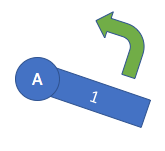

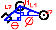
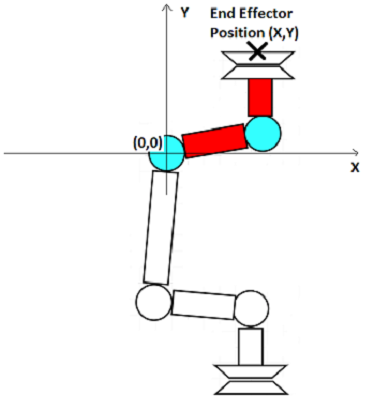
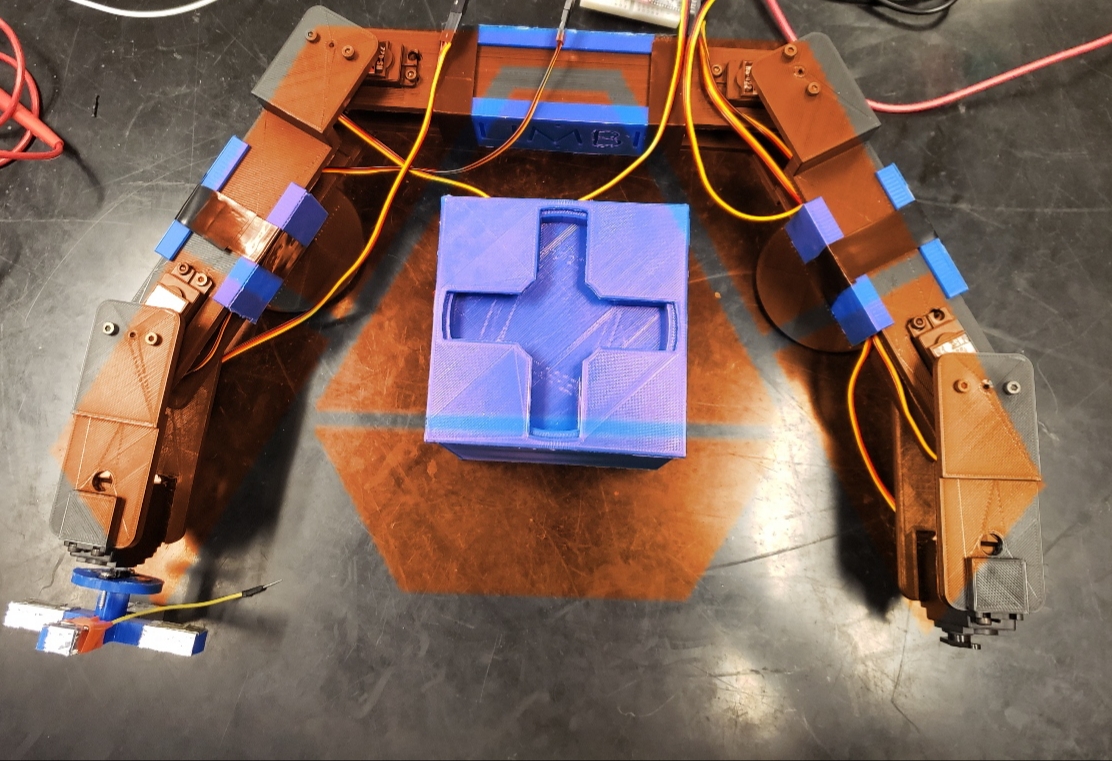
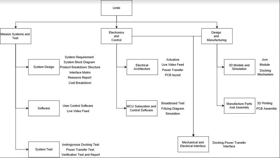
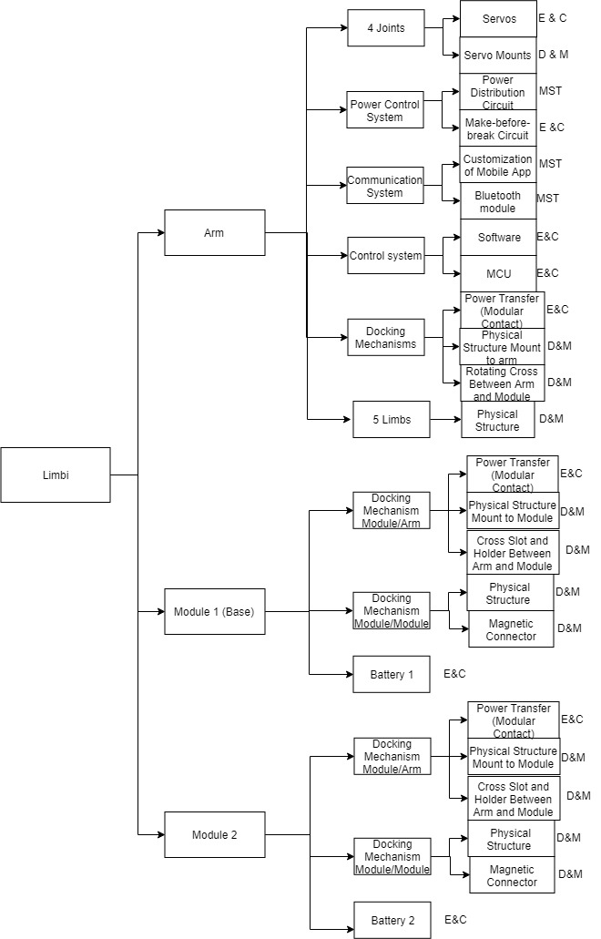
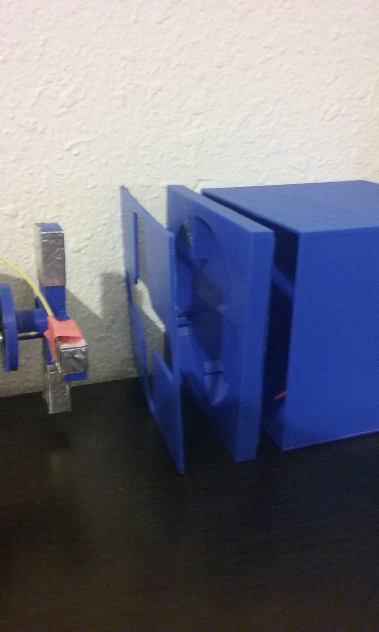
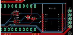
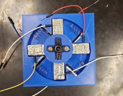
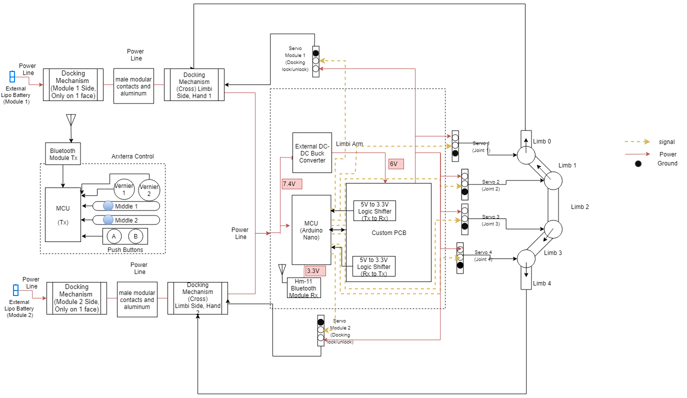
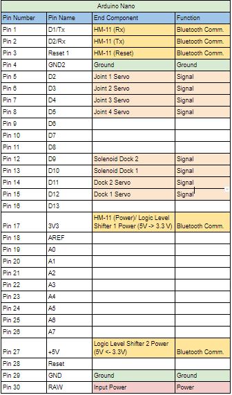
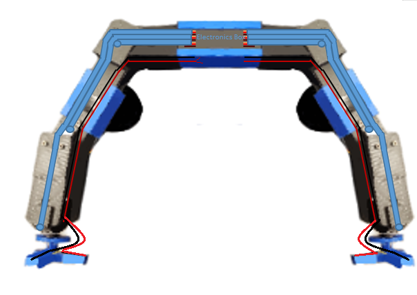
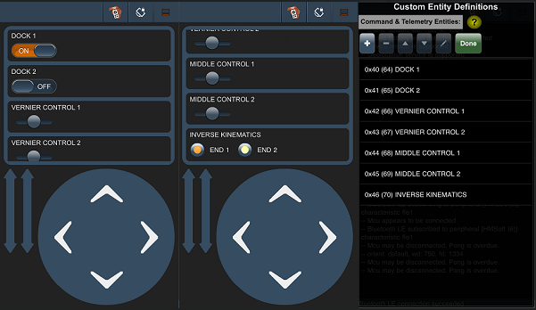
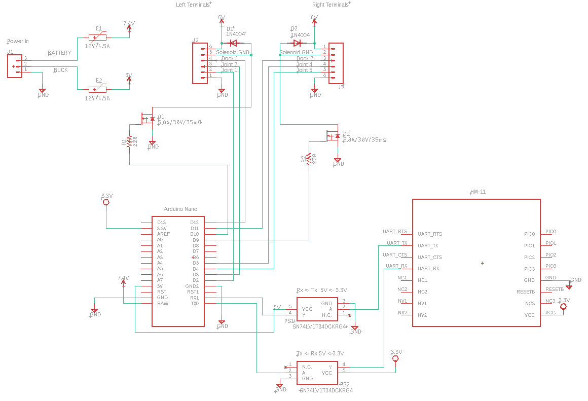
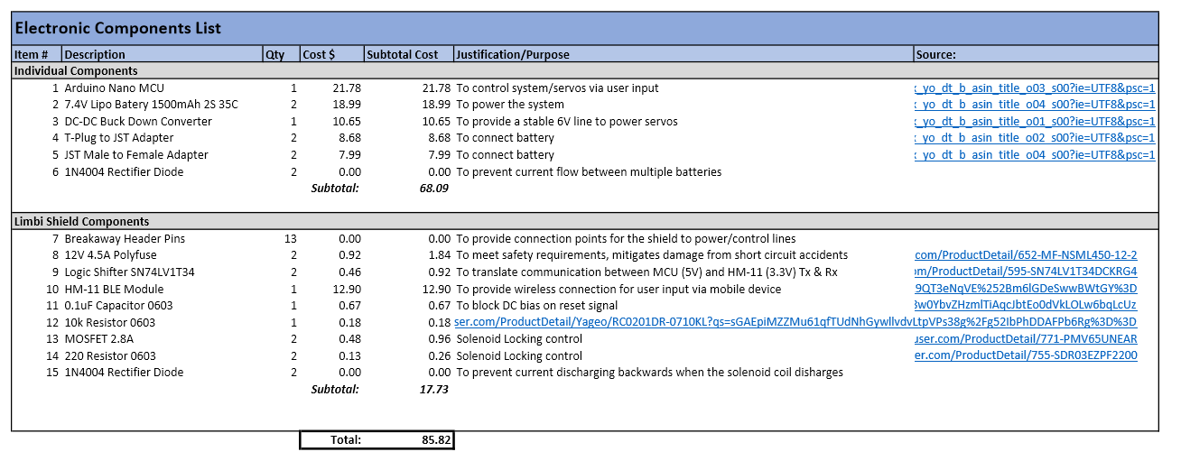
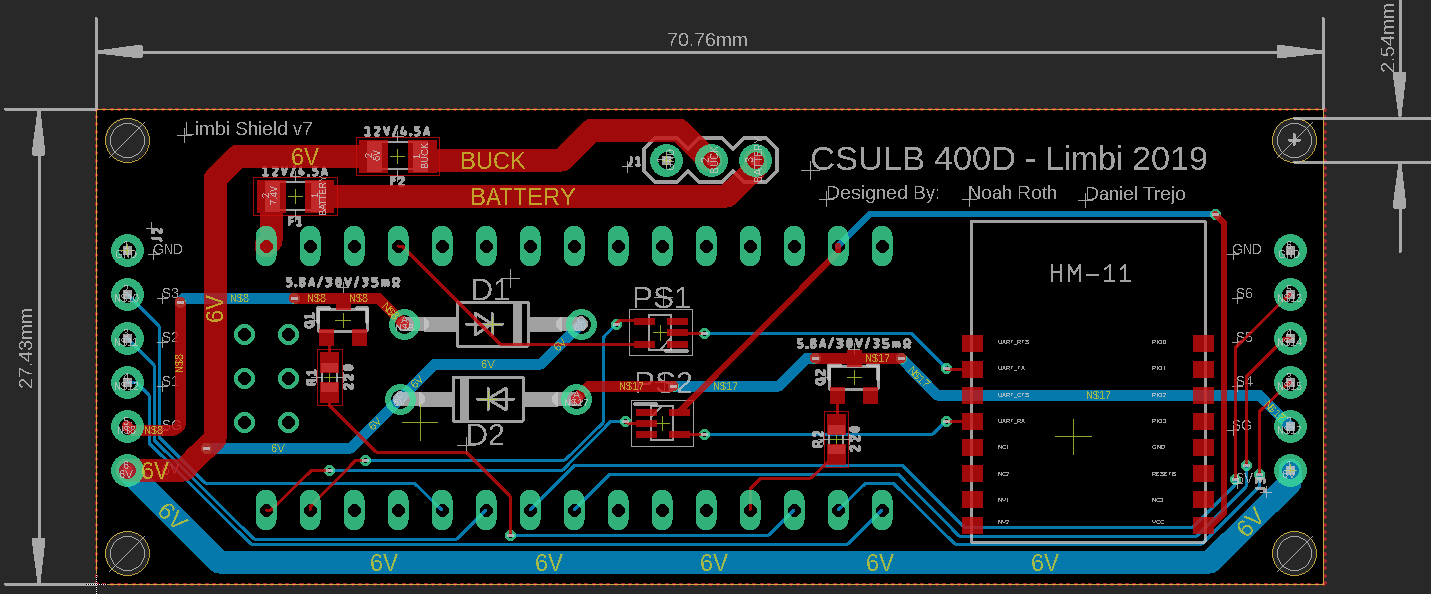
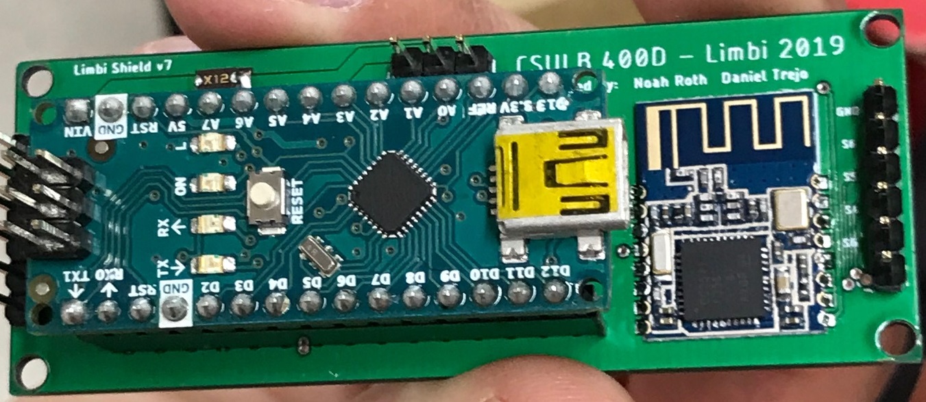

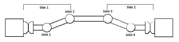
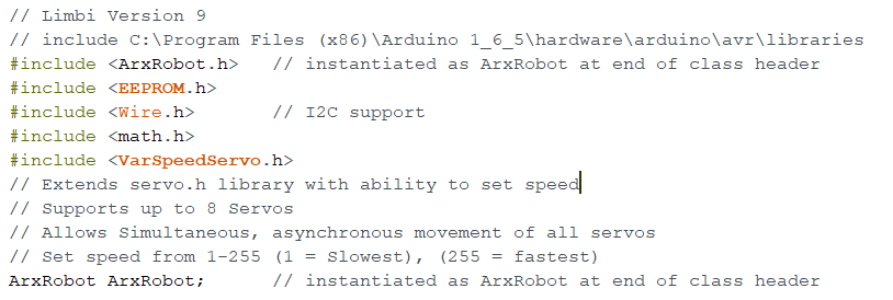
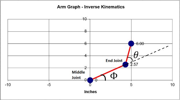

 Figure 1. Initial Breadboard Layout
 Figure 2. Initial Battery Board Schematic
 Figure 3. Initial Battery Board Layout
 Figure 4. Buck Converter
 Figure 6. Initial Shield Board Layout
 Figure 8. Final Shield Board Layout