By: Paul Ahumada, Project Manager
Members:
Kevin Armentrout, Electronics and Control Engineer
Victoria Osaji, Manufacturing and Development Engineer
Table of Contents
Project Overview
Mission Profile
3rd Generation Velociraptor is a robot developed by the CSULB 2016 Fall Semester class that will compete in a Jurassic/Modern Game: Save The Human with other toys on the last day of class, December 15, 2016. The game will involve Velociraptor chasing another robot through various terrain by tele-robotic communication on the Arxterra Control Panel. The arena and terrain the Velociraptor must traverse is developed by the Game Committee. The mission will display the robotic applications of the 3DoT Board developed by Arxterra and Velociraptor’s movement capabilities. – PM Paul Ahumada
Project Objectives
- The Velociraptor is a dinosaur toy
- The Velociraptor is on a deadline
- The Velociraptor will use a 3DoT board
- The Velociraptor will be controlled by an Arxterra Control Panel
- The Velociraptor will play in a game
The premise of the Project Objectives is that they are derived from the Mission Profile. These objectives that have been simplified will establish every requirement that will be used to build the Velociraptor (Th) robot.
System Design
System Block Diagram
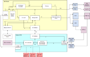
The system block diagram is an overview of what is needed int he project. Different systems can be viewed from this picture. The blue colors are for the linear actuators and sensors not located on the external PCB or 3DoT Board. Purple is for the mechanical characteristics of the robot. Red is for external power that is not on the external PCB or 3DoT Board.
One unique modification to the 3DoT board is bypassing the boost converter which can be seen in the System Block Diagram image. There was a current limit to the boost converter the Velociraptor team wanted to avoid because the maximum currents for the DC motors was above the current limit for the boost converter and polyfuse and be detrimental to a demonstration if an issue occurred.
Subsystem Design
Interface Definitions
Interface Matrix
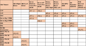
3DoT Board Available Pins
The interface matrix for available pins lets the Velociraptor Team know what is readily accessible to use and which connector it will be located at. It is as if one looks at the 3DoT board as a black box with several inputs and outputs. The Available pins has every input and output located on the 3DoT Board and what it will be connected to in the project. The rows are what the 3DoT Board has and the columns are what the team intends to connect to the 3DoT board.
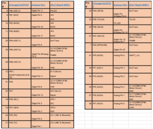
MCU Pins
The MCU Pin connections image purpose is for coding. Every pin from the MCU is accounted for and the programmer can determine what they intend each pin’s function. There are pins on the MCU that cannot be accessed and have end traces and are left as ‘end trace.’
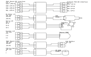
Wiring Diagram
The wiring diagram is generated from feedback of the electronics and control engineer and is utilized as a reminder for what connections to purchase and what space must be allowed when sizing the mechanical model. The connectors for each actuator, external PCB, or sensor are labeled so no confusion occurs when assembling the PCB board.
Mission Command and Control
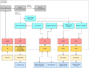
Software Block Diagram
The Software Block Diagram began the process of writing the firmware and finding the needs for inputs from Arxterra. The software block diagram has a light blue color where firmware will take over coding. For static and dynamic walking, the robot needs to differentiate between the walking style and the easiest method to implement that was to have a dynamic push button.
An addition to the diagram would be that was originally not required of the project. As a goal, the team made it a challenge to send telemetry back to Arxterra.
Arxterra App and Arxterra Control Panel
Arxterra Phone App
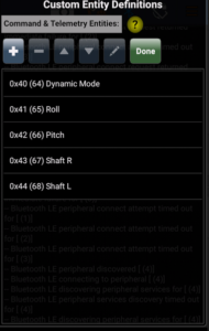
When customizing the needs for Velociraptor’s custom Telemetry and Commands, the MST needed to start with the phone app. The phone app has custom command and telemetry Custom Entity Definitions that can be created and modified.
For telemetry, the team was interested in reading numerical values of roll, pitch, shaft right of the leg, and shaft left of the leg. Pitch and Roll are rotation angles from 180 to -180 degrees. The shaft positions are 0 to 360 degrees for the legs. The four variables are all singles (4 bytes) being sent to Arxterra Control Panel.
For commands, a dynamic mode button (boolean) would allow users to change between static and dynamic mode. By pressing the button, the servo used to control the body would be turned on/off.
Arxterra Control Panel
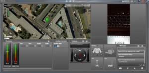
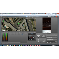
The layout of the Arxterra Control Panel is generated after choosing the entities from the Arxterra App on the phone. The custom command and telemetry is displayed along with GPS and a live stream feed of video from the user’s phone.
Custom Commands and Custom Telemetry
Defining Custom Commands and Custom Telemetry and Declaration of Custom Command Functions
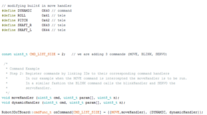 The custom commands and telemetry are defined at the beginning of the program to reserve their address space. Numbers below 0x40 are already defined elsewhere for built in commands and telemetry.
With newer versions of Arduino, functions that will be used for the custom commands are created before setup where the variable declaration is, similar to C++. The custom command for the dynamic button and move handler are used for Velociraptor. The reason a custom move handler is used is because there needed to be modifications for the motor control of the robot. The 3DoT board was designed for use with wheeled robotics and the Velociraptor is a biped. The DC motors need to be controlled with precision, which will be defined in firmware.
Telemetry Classes
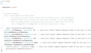
![]() The defined variables for telemetry are implemented into this section with the Packet Class. The constructor reads the unique variables so telemetry can be sent as different objects all part of the Packet Class.
The defined variables for telemetry are implemented into this section with the Packet Class. The constructor reads the unique variables so telemetry can be sent as different objects all part of the Packet Class.
For telemetry being sent to Arxterra, a local variable is created that is cast into unsigned bytes. The local variable will be initialized as a casted variable setup elsewhere in the firmware. For example, the image above has a temp variable casted as an unsign_16 and the right shaft reads that value to be sent out with the class function ‘sendSensor(…)’.
Electronics Design
Servo Design
Motor Design
IMU Design
IMU Implementation
Schematics
Firmware: E&C
Debugging Wire Library
3DoT and IMU
PCB Schematic E&C
Schematic
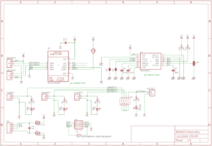
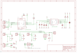
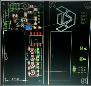
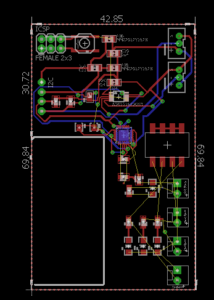
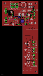
The schematic contains the SMD’s used for the external PCB required for Fall 2016. There is an I2C interface that has 4 wires coming from the 3DoT Board to the External PCB using Vcc, SDA, SCL, and Gnd.
Breadboard and Fritzing
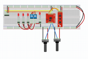
The schematic was placed onto a breadboard to see if the circuit behaved as the team wanted. The electronics and control engineer received outputs for the rotary sensors and the IMU sensor. These two sensors are what made our PCB external.
PCB Layout: MFG
Hardware Design: MFG
Mech-design
Verification & Validation Test Plans
validation_verification_testplans_r1
The Verification and Validation Test Plans is what our team had to complete for this semester. These items were determined by the customer in the Verification/Validation Matrices.
The test plans have pass/fail tests for each requirement. For our Project, we failed all dynamic tests because of the lack of time and capability to implement a dynamic control mechanical model. The team was also not able to create a dinosaur image that the customer wanted and failed validations.
Project Status
Power Allocation
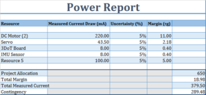
The Power Report shows that the Velociraptor team is at ~380mA and the Project Allocation is at 650mA. The robot at a 50% margin is 570mA and is thus at a safe operating range and has enough power being received to operate for over an hour based upon the CR123A being used.
Mass Allocation
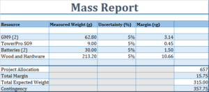
The Mass Report is based upon the torque needed to drive the robot, which is 657g at a 50% margin. The robot weighed 315g and that is below our 50% margin. The robot motors are capable of moving the mass.
Cost Report
The budgets were determined by the customer in October and this was based upon the cost allocations for each resource. The customer determined what could be provided and what could not be. In this report, their are items with $0.00 and they were provided by the customer. Items covered by the customer helped the team lower the budget to $95.71 and be below the Project Allocation set aside by the customer of $150.00.
Product Break Down Structure
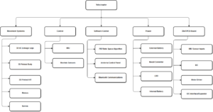
The PBS looked at different categories that would create this project. The image lets the team know all the items that need to be completed for the project in different categories.
Movement Systems encompass actuators and mechanical modeling. Control has the sensors. Software Control has communication and programming applications. Power has all components that use power or deliver. 3DoT/PCB has SMD’s and connections the team must be aware of during project building.
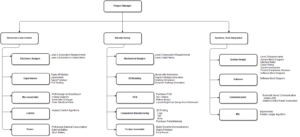
Work Break Down Structure
From the PBS, tasks are divided among the engineers through the WBS. This semester was unique because we lost our Systems Engineer and the Project Manager had to take over that position. Roles of the System Engineer were covered by both PM’s of each Velociraptor.
Schedule
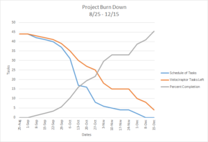
The Burn down Schedule has 3 graphs: expected project completion timeline (blue), actual project completion timeline (orange), percent completion (gray). As can be seen, the project lagged behind the expected project completion timeline and the team was forced to put in more time at the end of the semester. The complexity of the mechanical modeling, such as the legs, pushed back schedule and E&C’s capability to test the robot.
The project is 91% complete and misses implementation of rotary sensors with IMU, UCI linkage leg design, foot design, and firmware control algorithm.
Schedule-documents
Conclusion
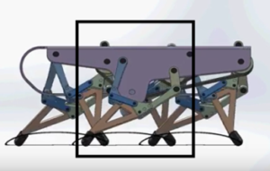
The Velociraptor Project had challenges that proved difficult to get around. The UCI or Theo Jansen Linkages could not be implemented because the Simulation verse Real-world creation of the linkages was different. The delays caused by the leg sets pushed back the control algorithms used to move the robot and a simplistic version had to be created for final project demonstration. Also, the foot design for any biped is something that needs to be handled in the beginning and likely require an actuator to maintain the robot’s stability.
For future projects, the mechanical modeling is crucial to focus on because it will cause the project to fail. Lessons to take from this semester are:
- Focus on leg linkage design early. How the linkages move when connected with screws is different than how they move in Solidworks
- Do not ignore the foot design. The foot must be parallel with the body and the ground to increase stability. If not, the CoG will change as the pitch angle changes
- Have Electronics and Control Engineer be familiar with I2C communication. The team was lucky to have an engineer more than capable of finding solutions to problems with I2C addressing locations for the sensors
CDR Document
PDR Document
BOM
Video
https://www.youtube.com/watch?v=ZV5TsYA7mLc

