Category: Communites

  • Servo Protection Methods Trade-off Study

    Servo Protection Methods Trade-off Study

    By Kevin Huynh, Project Manager / Computer Systems and Software

    Objective:
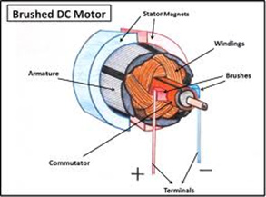
    For Spring 2014, one of the requirements for the biped is to add in some form of servo overcurrent protection. The goal of this is to prevent the servos from drawing too much current, overheating, and destroying the control circuit boards inside of the case. A situation where this can happen is when the servos are stalled from reaching their desired position, but they continue to draw the maximum current possible–2.3 A at 4.8 V for the Power HD1501 MG servos from the following datasheet:
    http://www.pololu.com/file/0J729/HD-1501MG.pdf

    The LiPo battery pack used for ROFIA is the Turnigy 1300 mAh 2S 20C LiPo pack, found below:
    http://www.hobbyking.com/hobbyking/store/__9165__turnigy_1300mah_2s_20c_lipo_pack.html

    This battery pack can easily supply 2.3 A for all twelve of the servos if they were all to stall at the same time.

    calculation copy

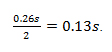
    The above calculation shows the LiPo battery pack can safely and continuously deliver up to 52 A to the servos for about 3 minutes, which is more than enough to supply the stall current to all of the servos simultaneously (27.6 A).

    Possible Solutions:
    The two methods that were considered for servo overcurrent protection were foldback current limiters and resettable fuses.

    Table copy

    Solution Chosen for the Biped:
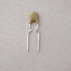
    The resettable fuses were chosen for their low cost, simplicity of implementation, and because the specifications needed were easier to find on a polyfuse than a foldback current limiter IC. The drawbacks of the polyfuses can be mitigated by replacing the polyfuses as they trip by inserting the polyfuses into female headers soldered onto a protoshield, rather than soldering the polyfuses themselves. Since the stall current of the Power HD 1501MG servos is 2.3 A at 4.8 V, the 06R120BU Littelfuse was chosen.
    http://www.mouser.com/ProductDetail/Littelfuse/06R120BU/?qs=sGAEpiMZZMsxR%252bBXi4wRUCTGuoKQj3D%2fwUhoRMyepPw%3d
    http://www.mouser.com/ds/2/240/Littelfuse_USBR-36712.pdf

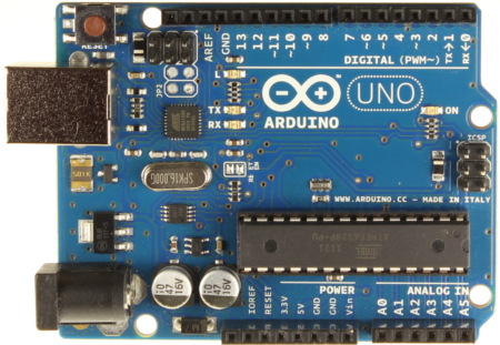
    The main specification that was taken into consideration when choosing a polyfuse was the trip current. Since the stall current of the Power HD 1501MG servo is 2.3 A at 4.8 V, the polyfuse trip current was chosen to be 2.0 A. This ensures that the polyfuse will trip before the servo can reach the stalling current and damage itself. Other specifications, such as the hold current and maximum voltage, were satisfactory for the biped. The hold current rating of 1.2 A is well below the stalling current, so it is a safe operating current for the Power HD 1501MG servos. Since the output voltage of the UBEC is approximately 5.3 V and the operating voltage of the servos range from 4.8 V to 6.0 V, the polyfuse maximum voltage rating of 6 V is acceptable. The connections between the LiPo battery, UBEC buck converter, polyfuses, and servos are shown below. The servo pulse pins connect to digital pins on an Arduino Mega ADK.

    servoProtection

  • Design – First Iteration

    Design – First Iteration

    By Simon Abatay, 3D Modeling and Manufacturing

    After a review with the Robot Company’s President, the initial tibia design was deemed unsatisfactory due to its flat nature. In order to tackle this, I decided to modify my original design to give it a more 3-dimensional appearance. My intentions with this modification step were to maintain some semblance of its original shape, while providing it with a newfound presence of solidity.

    Blog6_image1

    The picture above shows that there is a defined depth in all 3 axes of the tibia. This satisfies the 3-dimentional objective.  The tibia still retains its 7 inch height and has a shape similar to the initial design to satisfy the height requirement. In order to save weight, the inside of the tibia will be slightly hollow. The overall design will be constructed with enough material to retain the structural integrity of the tibia despite its hollowness. Below is an image of multiple views of my tibia design:

    Blog6_image2

    To test the quality of the design, I put it through a proper stress simulation in Solidworks©.

    Blog6_image3

    The green arrows in the image above show where the tibia will garner most of its support. The purple arrows represent where the external forces are being applied to the design. I chose to apply force in every possible direction against the bottom of the tibia. This was done in order to simulate the idea of the spider walking, since that motion is the time when tibia undergoes stress in all directions. The spectrum to the right of the picture shows the level of stress each section is undergoing. The stronger the section the more blue it is, and the weaker the section, the more orange and red. This simulation shows that when the tibia undergoes 50 Newtons of force in each direction, it can retain its shape with minimal deformation. This simulation shows that the tibia’s structure is sound.


  • Mission Objective Modified

    Mission Objective Modified

    By Kristine Abatay, Project Manager

    Following the group’s preliminary design review presentation, we met with the Robot Company’s President and modified our mission objective. Our new mission objective is:

    Complete a hexapod robot project whose creation will achieve a speed that matches the current Robot Company rover project, operate safely, be capable of maneuvering a predetermined route in a forest-like setting, and have a body comprised of three-dimensional components.

    Trickling down from this objective allowed us to create a fifth project requirement:

    5. The legs and chassis components of Spiderbot will be designed to have three dimensions.

    The other project requirements can be found ina previous post where the project was introduced:

     https://www.arxterra.com/spiderbot-life-times-vol-2/

    Additionally, the following tests have been created to verify the project requirements that have been written (they are listed in the order from which they have been introduced):

    Verification Tests:

    Test 1
    If project Spiderbot is completed by May 12, 2014, then this requirement will have been achieved.

    Test 2
    In order to verify the speed requirement, a flat surface, straight-lined course will be measured out and Spiderbot will complete the course while being timed. The resulting quotient of the length of the course, with the amount of time it will take Spiderbot to complete the course, will be calculated. If this value is equal to or less than the calculated rover speed, then requirement will have been achieved.

    Test 3
    The CSULB College of Engineering Health and Safety Policy states that “Faculty…shall: Implement the university’s Health and Safety Policy and all other university safety programs in work areas under their supervision/control.”

    If Professor Hill, a faculty member of the CSULB College of Engineering, approves the operation of Spiderbot in the classroom, then this requirement will have been met.

    Test 4
    Verification of the height requirement will be done by measuring the height clearance, as well as the length of one leg sweep of the fully constructed Spiderbot.

    Test 5
    The requirement of a three dimensional design will be verified within the SolidWorks program, which enables our manufacturer to define the three axes of a design. If, at any rotated view of a component design, three separate pieces of the design can be chosen to define a respective x-, y-, and z- plane, then this requirement will have been fulfilled.

  • Speed Calculations & Component Modification

    By Matthew Clegg, Computer and Control Systems

    In order to tackle the initial calculated speed requirement of the rover project, we would need a starting point for Spiderbot. For this reason, I decided to make a calculation to determine the speed that the servo motors on Spiderbot’s legs would need to move in order for the entire robot to match the rover speed.

    To try to estimate a possible speed for Spiderbot, I first calculated a velocity based on the speed of the servo motors. A servo’s rated speed is how fast, in seconds, the arm can move 60 degrees. To apply this to Spiderbot, I took into account the motion of the bot in a tripod gait, which is the most efficient walking pattern.

    Assuming the length of the femur to be 5” (the value assigned to the initial Spiderbot design done by Simon Abatay in manufacturing) and the femur moving forward at a 60 degree angle (the speed rating provided by servo motor specification sheets), then using trigonometry,

    eqn1 

    In SI units, each sweep of the leg will cover 0.109 meters. In the tripod gait, the leg will move up 30 degrees, forward 60 degrees, then back down 30. Knowing the sweep of the leg is 0.109meters, he came up with a formula to find the time in seconds

    eqn2

    Dividing this time by 2 to account for both motions of the gait results in

     eqn3

    The total degree movement of a leg is 30, 60 and 30 degrees. He divided 0.26s by two to find out how fast the servo moves 60 degrees to reach a speed of

     eqn4 

    These calculated values are our project’s starting point. They are subject to change once more progress is developed with the rover project and more concrete details are obtained.

    Lastly, it has come to our attention that using both the Mega ADK microcontroller and Adafruit breakout boards (as stated in a previous blog post for this project) would be redundant. The Mega ADK was considered because it could accommodate the amount of servos we would need to construct Spiderbot. Breakout boards were considered because it was the route that both spider projects took last semester in terms of design. We decided to instead use the breakout boards along with an Arduino Uno R3 microcontroller since we already have one in our possession, so the decision was mostly based out of convenience. Using these two components together will essentially be the same as using a single Mega ADK. An image of our newly chosen component can be seen below:

    Blog4_image1 (1)
     (Image found at: http://arduino.cc/en/Main/arduinoBoardUno)


  • Spiderbot: Initial Design

    Spiderbot: Initial Design

    By Simon Abatay, 3D Modeling and Manufacturing

    Picking up from last semester’s Spiderbot project, the design for this project will have 6 legs. Though the name ‘spider’ implies 8 legs, translating it to a project would become very pricy in the long run since it would require more materials and power to construct.

    Despite the difference in leg amount, we still wanted the design to be similar to an actual spider. The image below is of an actual spider leg. From this, we can see that spiders have 7 joints.

    Blog3_image2

    (Image from: http://havoc20.wordpress.com/2010/11/13/spider-tibia-structure/)

    This would translate to seven servo motors per leg, and at 6 legs that would mean 42 servo motors! To save money on the final design, we’ve reduced our spider leg design to the 3 main parts: the coxa, femur, and tibia. This is the case with most hexapod designs that can be found online.

    Three joints with a single motion each will mean each leg will have three degrees of freedom. This reduction will provide smooth movement for Spiderbot while walking and enough support for the spider to stand when stationary.

    Keeping the reduction of joints in mind, the following image is my initial design of the spider’s tibia, which was created in the program SolidWorks.

    Blog3_image3
    One of the main issues with last semester’s design was maintaining balance while stationary. To avoid this, each tibia portion will have a tibia “plate” on opposite sides of the servo motor. To keep the whole tibia portion from collapsing on itself, each pair of tibia plates will be supported by metal spacers or standoffs.

    The tibia will measure 7 inches in height as a response to the project requirement of clearing an obstacle of 4 inches tall, located in the planned route for Spiderbot.

    For the body portion of Spiderbot, I plan to use a circle-based design since its shape will alow for uniform weight distribution. This way, the tibias will be evenly spaced out and, assuming the hardware will be placed in the middle of it, the center of gravity will remain at the middle of the Spiderbot.

    Blog3_image4

    The image below shows the design of the base plate. The radius of the center portion is 3 inches to accommodate the power source, the microcontroller, the servo breakout boards, and the Android© based cellular phone.

    Blog3_image5

    The extensions of the circle have a radius of 4.4 inches to accommodate the servos and their proper positioning (see rectangular cutouts).  The rest of the cutouts are for weight saving and heat ventilation. Seeing as a solid plate would have unwanted and unnecessary weight, it would be best to make cut-outs of the plate while at the same time leaving enough mass and surface area for the other components.

  • Wheel Consideration

    Wheel Consideration

    by Robert Licari and Anthony Vo

    We can take the wheels into consideration for the purpose of finding our desired velocity based upon our calculations.

    If our Wheel Diameter (D) is 45 mm, then we can conclude the Radius (R) is as follows:
    R= D/2 = 0.0225 m

    Now we require a velocity equation that relates velocity to our wheel. For this task, we can employ a basic velocity equation with relation to angular velocity:

    V = (R*w)/sin(theta)

    Where “w” is angular velocity and our conversion from RPM to rad/s is as follows:

    1 RPM = (2*pi )/60 rad/s

    The spec that we have four our free-run RPM is 85 RPM @ 6V, which we shall use to find our normal velocity. In tandem with this, our application of the wheel requires that the angle “theta” be 90 degrees, or perpendicular, to our rotational axis, which effectively gives us:

    V = 0.0225m * [ 85 RPM * (2*pi/60 rad/s) ]
     =~ 0.2003 m/s

     This equation can be applied to varying Diameter, but, for our purposes, we will use the 45 mm wheel.

     Level 1 Requirement:
    — Speed according to the wheel diameter —

     The velocity requirement is defined base on matching the velocity of the standard ROSCO.  To calculate the velocity of the ROSCO, the circumference of the wheels and RPM of the motors is taken into account.  Given the wheel diameter, the circumference of the wheel can be calculated.  After scaling the measurements to meters and seconds, the rover is expected to have a velocity of at least 0.200277 m/s or ~0.2003 m/s.

  • Power Consumption Theory

    Power Consumption Theory

    by Robert Licari and Anthony Vo

    Before we begin it is imperative to note that the power consumption equations calculated are heavily related to the amount of torque required to move the motors from rest to forward motion. In accordance with that idea, the following theory is calculated considering the worst power conservation possible. By that, we mean that there is probably no way that the Rover will draw this much power, but the fact of the matter remains that the equations are scenarios that can, and probably will happen. Our theory at this point considers that these scenarios are happening constantly.

     Having said that, we can do some simple addition in order to compare our power consumption:

     Power_DCMotor + Power_Servos = Motor Power Consumption

     5 W + 3 W = 8 W

     Now if we do a simple calculation involving the current, we can find the total current drop that the Rover will consume:

     8 W = 8.4 V * I_total

     I_total = 0.9524 A

     If our battery output is 800 mAh, then we can easily state:

     Operational Time = 0.8 Ah / 0.9524 A = 0.84 h

     0.84 h ~ 50 mins

    Given our simple calculations and considering only the power consumption of the motors itself operating constantly at their rated voltages, we should be able to run the motor for approximately 50 mins.

    Bear in mind that this is an ideal situation and is not considering physical constraints and is assuming constant heavily-powered motion from our motors. The reason the calculations were done this way is to illustrate a time that was within our overall assumptions as well as a starting point for the next phase of calculations being the physical constraints of our payload (the rover itself) as well as additional power concerns involving the microcontroller.

  • Subsystem Requirements: Power Budget

    Subsystem Requirements: Power Budget

    by Robert Licari and Anthony Vo

    Power supply of the Rover:
    Rover must provide sufficient power to clear the course of 50m.

    To ensure that the rover is able to complete its mission in a timely fashion, the rover’s load cannot exceed 6.72 Wh. For this to be true, we must consider how much power and current draw will go into each of our major components powered by this battery pack. In accordance with this math, we should be able to run approximately 13 W of power during the duration of 30 mins. Keeping this in mind, we will continue with the analysis of our motors.

    DC Motor:

    120:1 Plastic Gearmotor 90-Degree Output


    Typical operating voltage: 6 V
    Gear ratio: 120:1
    Free-run speed @ 6V: 85 rpm
    Free-run current @ 6V: 70 mA
    Stall current @ 6V: 800 mA
    Stall torque @ 6V: 75 oz·in

    The single most important consideration that we have is with our DC Motors. We will be running two motors which will alter the above specifications as follows:

     Stall current @ 6V =>            1.6 A
    Stall Torque @ 6V =>            1.05924 N-m   (converted from 150 oz*in)

    Given this information, we will be able to determine that ~1 N-m of torque is where our DC motor will stall a will effectively put us dead in the water. So long as our torque remains underneath this value we can safely say that our current draw will be under 1.6 A and that our motors will not stall.

     For this purpose, we will be working backwards. Our considerations will work from an outlandish power involving our Stall values, and we will be able to take steps backward in order to figure out where we want to be in terms of power usage and current draw.

     Therefore, we will, once again, use our power equation utilizing our stall values and our rated voltage:

    P_stall = V * I_stall
    P_ stall = 6V * 1.6 A

    = 9.6 W

    This value is our stall power for both of our motors at Stall. Now, we do not wish for our motors to stall because that would be detrimental to our fundamental mission objective of forward motion. Therefore, we will simply scale backwards from our stall power and find a current draw that will fit with the specifications of our battery pack.

     Here are some basic equations demonstrating this:

    Let I = P / V
    If P = 9 W then
    9 W / 6 V = 1.5 A

    If P = 5 W then
    5 W / 6 V = 0.83 A

     If P = 3 W then
    3 W / 6 V = 0.5 A

    These current values will be considered when we bring our Rover from rest to forward motion, and are integral to the mission objective. From a purely theoretical standing, the motor will never draw this much power at free-run, but we must also consider that the amount of time that our rover is at free-run speed will be minimal given the nature of the course we must navigate. Taking these into consideration, it is best to err on the side of the worst case scenario in order to avoid the necessity for a new battery pack or motor.

    To meet our loose requirement for under 13 W of power consumption, if we consider our motors to draw about 5 W collectively, we are well under the power consumption thus far.

    Also, do keep in mind that we are using the specification of 6 V, which can be subject to change as a work-around for our power budget.

    Servo Motor:

     Towerpro MG996R 10kg servo
    Weight                                    55g
    Dimension                              40.7*19.7*42.9mm
    Stall torque                            10kg/cm = 0.01 kg/m
    Operating speed                    0.20sec/60degree(4.8v)
    Operating voltage                  4.8-7.2V
    Temperature range               0_ 55
    Servo Plug:                             JR (Fits JR and Futaba)

    Just like for the DC Motor, we will consider a purely electrical requirement. We will use the same approach that we have used previously but utilize different formulae in order to account for our different specifications.

    Our first goal was to find an equation that could accurately and easily find a reasonable power consumption. Therefore, we will be using this equation:

    P = ( N * T ) / C_1

    For the use of this equation, we will use the fact that N is the number of revolutions per minute (RPM) and that C_1 is a Torque conversion constant related to the desired units of power that follows the below table

    We must also consider that our operating speed is in improper units as well. So we will use the conversion provided by our conversion calculator (see Sources), which will give us the following:

    0.2s / 60 degrees = 1/300 s/degree

     => ~50 RPM @ 4.8 V

    Now that we have our operating speed in RPM, we can begin using our new power equation in order to discover what our stall power is and work backwards just as we did with the DC motor.

    If P = ( N * T ) / C_1

    Our stall power will be the following:
    P_stall = ( N * T_stall ) / C_1
    = ( 50 RPM * 10 kg/cm ) / 97.3

    = 5.1387 W

    This tells us that our maximum power before stall is ~ 5 W at our operation voltage of 4.8V. Now if we work backwards just as we’ve done before:

    If P = 5 W then
    5 W / 4.8 V = 1.0417 A

    If P = 3 W then
    3 W / 4.8 V = 0.6250 A

    For our application here, we have a tremendous amount of flexibility with the servos. Unlike the DC Motor, the servos will not be running constantly in order to fuel our objective, but we must also consider that there is a finite amount of power that we have at our disposal. Therefore, if we propose that our servos run at approximately 3 W collectively then we can use that in our calculation of our battery life.

  • Hexapod Forward and Backward Movement Calculation and Algorithm

    By Chau To

    Introduction:
    Hexapod uses the tripod gait (3-leg combined showed in Figure 1) to perform forward and backward movement. In order for the Hexapod to move in a straight line, it is required all of the servos such as shoulder, femur, and tibia servo to be operated simultaneously. This blog post will give a detail calculation for the angle that each servo needs to make to compensate with one another. This blog post will also introduce the algorithm for the Hexapod forward and backward movement.

    Hexapod Movement Analysis and Calculation:
    The Hexapod will use 3 legs at the same time for movement as showed in Figure 1.

     figure 1

    Each leg composed of a femur and a tibia and is controlled by 3 servos: shoulder servo, femur servo and tibia servo as showed in Figure 2. 

    figure 2


     Forward and backward movement analysis:
    When the Hexapod is moving, if the Tibia servo does not rotate, the Hexapod body will be shifted by the “x” distance (bottom picture in figure 3.) The purpose of the following calculation is to find the angle of the Tibia and Femur to compensate and to prevent the “shifted body problem.”

    Let’s declare the variable like in figure 3:

    figure 3


    • F is the length of the Femur (from the shaft of the Femur servo to the shaft of the Tibia servo)
    • T is the length of the Tibia (from the shaft of the Tibia servo to the ground)
    • α is the angle of the Tibia assuming that the initial position of the Tibia is perpendicular to the ground.
    • β is the angle of the Fumur assuming that the initial position of the Femur is parallel to the ground.
    • A is the project of the leg on the ground
      • θ is the angle the shoulder servo rotates
      • x is the distance that the body is shifted

     Let’s α’ be the new angle of the Tibia servo to compensate the x distance:

     The angle that the Tibia servo has to adjust:

     In order to balance the Hexapod, the Femur servo also has to rotate to a new angle

    Let’s y is the length the Femur need to compensate like in Figure 4

     figure 4

    Let β’ be the new angle of the Femur servo to compensate the x distance:

     The angle that the Femur servo has to adjust:

    Example: Hexapod matching the speed of the Rover 0.2m/s
    In order to match the speed of the Rover, each Hexapod step needs to be 4 inches assuming that the Hexapod takes 2 steps in 1 sec, and the speed of the Rover is 8 inches/s

    Let the length of the Femur: F = 3 inches, length of the Tibia: T = 6 inches, and α = β = 300

    • A = 6sin(30)+3cos(30) = 5.5980 inches

    To reach 4 inches, Let θ = 450  à Hexapod step will be: Asin(45) = 3.958 inches.

    So, with this setting, the Hexapod should be able to match the speed of the ROVER!!!

    Let calculate the angle of the Tibia and Femur for the forward movement:

    • x = A – A cos(θ) = 5.5980-5.5980*cos(45) = 1.159 in
    • α’ = 43.88660
    • ∆α = 43.8866 – 30 = 13.88660 (from initially 300 to 43.8860)
    • y = 0.8718 in
    • β’ = 120
    • ∆β = -180 (from initially 300 down to 120)

    In summary, in order for the Hexapod to move in straight line with a step of 4 inches with the settings in the example, the shoulder servo needs to rotate 450; the tibia servo need to rotate an extra 140 and the femur servo also needs to rotate an extra 180.

    Movement Algorithm:
    Screenshot (33)

    Delay is very important because it requires certain time for each servo to rotate. Therefore, each delay makes sure that the previous stage is completed. Maximizing the delay also increased the performance of the Hexapod. 

    At the final stage when the shoulder servo rotates back to –θ, i.e it means that the servo rotate to the initial angle before the robot move. The delay between each rotation is very important and needs to be precise because each angle of the leg servos might be different from each other.

  • Motor Trade-off Study

    Motor Trade-off Study

    By Anthony Vo

    In order to decide which motor will meet our level 1 and subsystem requirements, it is important to conduct a trade-off study of several motors.  The goal of the trade-off study is to compare and contrast the RPM, current draw, torque, and cost of each motor.  From the trade-off study, we will be able to determine which motor will best fit out design specifications.


    Type of Motor

    plastic gearmotor

    GM8

    GM9

    GM10

    GM17

    Cost

    $5.75

    $5.75

    $5.75

    $9.26

    $5.75

               
    Voltage (vdc)

    6

    5

    5

    5

    6

    Current (mA) free-run

    70

    57.6

    73.2

    24.6

    29

    Power=IV (mW) electrical

    420

    288

    366

    123

    174

    RPM (speed)

    85

    70

    66

    370

    32.4

    Torque (oz-in)

    75

    43

    43

    3.6

    69

    Torque (kg-cm)  

    3.096

    3.096

    0.26

    4.97

    Torque (N-m)

    0.529

    0.303

    0.303

    0.025

    0.487

    Reduction

    120:1

    143:1

    143:1

    81:1

    228:1

    Weight (grams)

    32

    32


    5

    35

    Weight (oz)  

    1.13


    0.176

    1.23

    Above is a chart of 5 different motors with a hyper link to each one.  The description and specification for each motor is arranged into a chart for easy comparison.  From the data above, we have narrowed down our motor to 2 choices: the GM8 and the plastic gearmotor.

    GM8:
    The pros for choosing the GM8 over the plastic gear motor include lower current draw at free-run and lower power consumption.  The lower power consumption allows us to meet our power requirement defined in the subsystem requirements.  However, this motor will not provide the RPM required to achieve our speed requirement at the rated 5 volts.

    Plastic Gear Motor:
    The pros for choosing the plastic gear motor over the GM8 include higher RPM and higher torque rating.  The higher RPM ensures that our level 1 speed requirement is met.  This motor also provides more torque which will allow the rover to move over more difficult terrain without stalling.

    Conclusion:
    After comparing the two motors, we are leaning towards the plastic gear motor.  Although the motor is less power efficient, it will still meet the subsystem power requirements.  The plastic gear motor will provide the RPM and torque we need to drive the rover at our speed requirement.