Category: E&C – MCU Subsystem Command Programming

  • Troubleshooting & Bootloader Burning

    Troubleshooting & Bootloader Burning

    [av_heading tag=’h2′ padding=’10’ heading=’3Dot Troubleshooting & Bootloader Burning’ color=” style=” custom_font=” size=” subheading_active=” subheading_size=’15’ custom_class=” admin_preview_bg=” av-desktop-hide=” av-medium-hide=” av-small-hide=” av-mini-hide=” av-medium-font-size-title=” av-small-font-size-title=” av-mini-font-size-title=” av-medium-font-size=” av-small-font-size=” av-mini-font-size=”][/av_heading]

    [av_textblock size=” font_color=” color=” av-medium-font-size=” av-small-font-size=” av-mini-font-size=” admin_preview_bg=”]

    [/av_textblock]

    [av_heading tag=’h3′ padding=’10’ heading=’3Dot Troubleshooting’ color=” style=” custom_font=” size=” subheading_active=” subheading_size=’15’ custom_class=” admin_preview_bg=” av-desktop-hide=” av-medium-hide=” av-small-hide=” av-mini-hide=” av-medium-font-size-title=” av-small-font-size-title=” av-mini-font-size-title=” av-medium-font-size=” av-small-font-size=” av-mini-font-size=”][/av_heading]

    [av_heading tag=’h4′ padding=’10’ heading=’Error Codes’ color=” style=” custom_font=” size=” subheading_active=” subheading_size=’15’ custom_class=” admin_preview_bg=” av-desktop-hide=” av-medium-hide=” av-small-hide=” av-mini-hide=” av-medium-font-size-title=” av-small-font-size-title=” av-mini-font-size-title=” av-medium-font-size=” av-small-font-size=” av-mini-font-size=”][/av_heading]

    [av_textblock size=” font_color=” color=” av-medium-font-size=” av-small-font-size=” av-mini-font-size=” admin_preview_bg=”]
    When there is an error in a command sent to the Arduino/3DoT, a telemetry packet with an Exception Code will be returned. Below is a list of the possible Command Exception codes. Following that, an example showing how to read exception code telemetry is provided.
    [/av_textblock]

    [av_heading tag=’h5′ padding=’10’ heading=’Command Exception Codes’ color=” style=” custom_font=” size=” subheading_active=” subheading_size=’15’ custom_class=” admin_preview_bg=” av-desktop-hide=” av-medium-hide=” av-small-hide=” av-mini-hide=” av-medium-font-size-title=” av-small-font-size-title=” av-mini-font-size-title=” av-medium-font-size=” av-small-font-size=” av-mini-font-size=”][/av_heading]

    [av_textblock size=” font_color=” color=” av-medium-font-size=” av-small-font-size=” av-mini-font-size=” admin_preview_bg=”]
    The finite state machine for command processing and decoding will generate the exception or error codes listed below. These codes will be sent to the Arduino IDE “Serial Monitor” as well as telemetry to the ArxRobot App.

    01           Start byte 0xA5 expected

    02           Packet length out of range 1 – 20

    03           LRC checksum error

    04           Undefined command decoder FSM state

    05           Array out of range i >= 23
    [/av_textblock]

    [av_heading tag=’h5′ padding=’10’ heading=’Exception Code Example’ color=” style=” custom_font=” size=” subheading_active=” subheading_size=’15’ custom_class=” admin_preview_bg=” av-desktop-hide=” av-medium-hide=” av-small-hide=” av-mini-hide=” av-medium-font-size-title=” av-small-font-size-title=” av-mini-font-size-title=” av-medium-font-size=” av-small-font-size=” av-mini-font-size=”][/av_heading]

    [av_textblock size=” font_color=” color=” av-medium-font-size=” av-small-font-size=” av-mini-font-size=” admin_preview_bg=”]
    In this example, the camera home command is sent with an incorrect LRC byte to examine how exception codes work.

    A5 01 04 00

    Command Packet ID        = A5

    Packet Length N                = 01

    Camera Home                   = 04

    Parity                                    = 00       A0 = A5 ⊕ 01 ⊕ 04

    The telemetry packet (CA…) in Figure 12.1 was sent as a response from the 3DoT board when the command packet (A5 01 04 00 above) was sent. Looking at the command packet (start byte = A5), the user has sent a CAMERA_MOVE_HOME (3rd byte = 04) command with the LRC byte as 00. By calculating the LRC byte by hand (A5 ⊕ 01 ⊕ 04) it is shown that the correct LRC byte is equal to A0.

    The 3DoT firmware responds to this simulated data transmission error by sending telemetry packet CA 03 0E 03 A0 64 as shown in Figure 17-1.
    [/av_textblock]

    [av_image src=’https://www.arxterra.com/wp-content/uploads/2018/05/arduino_131.png’ attachment=’140235′ attachment_size=’full’ align=’center’ styling=” hover=” link=’lightbox’ target=” caption=” font_size=” appearance=” overlay_opacity=’0.4′ overlay_color=’#000000′ overlay_text_color=’#ffffff’ animation=’no-animation’ admin_preview_bg=”][/av_image]

    [av_textblock size=” font_color=” color=” av-medium-font-size=” av-small-font-size=” av-mini-font-size=” admin_preview_bg=”]

    Figure 17-1: Telemetry packet sent from Arduino/3Dot board.

    data[i] i = 0 i = 1 i = 2 i = 3 i = 4 i = 5
    Packet CA 03 0E 03 A0 64
    Description Packet ID Packet Length N+1 Command Exception ID LRC Checksum Error Expected Checksum Packet Checksum

    The “Telemetry ID” is 0E, which is sent indicating an error was detected when trying to decode the command. 03 indicates that LRC byte sent is incorrect. In this example, A0 is the expected LRC byte that is needed to be sent. Knowing this, if the user were to send the exact same command packet, but changing the LRC byte to A0 (A5 01 04 A0), the microcontroller will not reply with a telemetry packet again.

    Going back to the telemetry packet  (start byte = CA), the last byte is now the LRC byte for the telemetry packet (CA ⊕   03 ⊕   0E ⊕   A0 = 64). Again, this component is used to verify that all elements were read accurately.

    It is not important understanding how to find the LRC bytes for telemetry packets, as they are automatically calculated, but it is good to know the purpose of the LRC byte for data packets for both commands and telemetry and how it is computed by the software.
    [/av_textblock]

    [av_heading tag=’h4′ padding=’10’ heading=’Bluetooth Troubleshooting’ color=” style=” custom_font=” size=” subheading_active=” subheading_size=’15’ custom_class=” admin_preview_bg=” av-desktop-hide=” av-medium-hide=” av-small-hide=” av-mini-hide=” av-medium-font-size-title=” av-small-font-size-title=” av-mini-font-size-title=” av-medium-font-size=” av-small-font-size=” av-mini-font-size=”][/av_heading]

    [av_textblock size=” font_color=” color=” av-medium-font-size=” av-small-font-size=” av-mini-font-size=” admin_preview_bg=”]
    Connecting over Bluetooth can be finicky at times. If there are too many nearby sources try initially pairing to the 3Dot on your own (in isolation). If connecting still doesn’t work: first try restarting the 3Dot and rescanning Bluetooth within the app. If connecting proves to not work consistently try these steps:

    1. Turn off 3Dot
    2. Force Close Arxterra
    3. Turn off and on Bluetooth (in phone settings)
    4. Reopen Arxterra
    5. Then scan for devices within Arxterra

    [/av_textblock]

    [av_heading tag=’h3′ padding=’10’ heading=’Burning Bootloader and Fuse Settings’ color=” style=” custom_font=” size=” subheading_active=” subheading_size=’15’ custom_class=” admin_preview_bg=” av-desktop-hide=” av-medium-hide=” av-small-hide=” av-mini-hide=” av-medium-font-size-title=” av-small-font-size-title=” av-mini-font-size-title=” av-medium-font-size=” av-small-font-size=” av-mini-font-size=”][/av_heading]

    [av_one_fourth first min_height=” vertical_alignment=” space=” custom_margin=” margin=’0px’ padding=’0px’ border=” border_color=” radius=’0px’ background_color=” src=” background_position=’top left’ background_repeat=’no-repeat’ animation=” mobile_breaking=” mobile_display=”]
    [av_image src=’https://www.arxterra.com/wp-content/uploads/2018/05/arduino_132.png’ attachment=’140237′ attachment_size=’full’ align=’center’ styling=” hover=” link=’lightbox’ target=” caption=” font_size=” appearance=” overlay_opacity=’0.4′ overlay_color=’#000000′ overlay_text_color=’#ffffff’ animation=’no-animation’ admin_preview_bg=”][/av_image]
    [/av_one_fourth]

    [av_one_half min_height=” vertical_alignment=” space=” custom_margin=” margin=’0px’ padding=’0px’ border=” border_color=” radius=’0px’ background_color=” src=” background_position=’top left’ background_repeat=’no-repeat’ animation=” mobile_breaking=” mobile_display=”]
    [av_textblock size=” font_color=” color=” av-medium-font-size=” av-small-font-size=” av-mini-font-size=” admin_preview_bg=”]
    A bootloader is the first piece of code a microcontroller executes when it is powered ON. Usually, manufacturers burn the appropriate bootloaders into microcontroller chips prior to selling them. For instance, this is how computers recognize the type of Arduino plugged into it. However, dealing with a fresh microprocessor chip, the bootloader will have to be burned onto it before it is capable of being programmed. This tutorial will walk through how set the appropriate fuse settings and burn the 3DoT Bootloader to the board.
    [/av_textblock]
    [/av_one_half]

    [av_one_fourth min_height=” vertical_alignment=” space=” custom_margin=” margin=’0px’ padding=’0px’ border=” border_color=” radius=’0px’ background_color=” src=” background_position=’top left’ background_repeat=’no-repeat’ animation=” mobile_breaking=” mobile_display=”]
    [av_image src=’https://www.arxterra.com/wp-content/uploads/2018/05/arduino_133.png’ attachment=’140238′ attachment_size=’full’ align=’center’ styling=” hover=” link=’lightbox’ target=” caption=” font_size=” appearance=” overlay_opacity=’0.4′ overlay_color=’#000000′ overlay_text_color=’#ffffff’ animation=’no-animation’ admin_preview_bg=”][/av_image]
    [/av_one_fourth]

    [av_heading tag=’h4′ padding=’10’ heading=’Equipment’ color=” style=” custom_font=” size=” subheading_active=” subheading_size=’15’ custom_class=” admin_preview_bg=” av-desktop-hide=” av-medium-hide=” av-small-hide=” av-mini-hide=” av-medium-font-size-title=” av-small-font-size-title=” av-mini-font-size-title=” av-medium-font-size=” av-small-font-size=” av-mini-font-size=”][/av_heading]

    [av_textblock size=” font_color=” color=” av-medium-font-size=” av-small-font-size=” av-mini-font-size=” admin_preview_bg=”]

    • AVRISP mkII compatible USB programmer
    • 3DoT ICSP breakout
    • 3DoT Board
    • A PC with Atmel Studio 7 installed*

    * Or any computer with AVRDude usable through a command line interface (advanced).
    [/av_textblock]

    [av_heading tag=’h4′ padding=’10’ heading=’Connecting the 3DoT Board’ color=” style=” custom_font=” size=” subheading_active=” subheading_size=’15’ custom_class=” admin_preview_bg=” av-desktop-hide=” av-medium-hide=” av-small-hide=” av-mini-hide=” av-medium-font-size-title=” av-small-font-size-title=” av-mini-font-size-title=” av-medium-font-size=” av-small-font-size=” av-mini-font-size=”][/av_heading]

    [av_one_half first min_height=” vertical_alignment=’av-align-top’ space=” margin=’0px’ margin_sync=’true’ padding=’0px,0px,15px,0px’ border=” border_color=” radius=’0px’ radius_sync=’true’ background_color=” src=” attachment=” attachment_size=” background_position=’top left’ background_repeat=’no-repeat’ animation=” mobile_breaking=” mobile_display=”]
    [av_image src=’https://www.arxterra.com/wp-content/uploads/2018/05/IMG_20190721_193223-min-287×300.jpg’ attachment=’149998′ attachment_size=’medium’ align=’center’ styling=” hover=” link=” target=” caption=” font_size=” appearance=” overlay_opacity=’0.4′ overlay_color=’#000000′ overlay_text_color=’#ffffff’ animation=’no-animation’ admin_preview_bg=”][/av_image]
    [/av_one_half]

    [av_one_half min_height=” vertical_alignment=” space=” custom_margin=” margin=’0px’ padding=’0px’ border=” border_color=” radius=’0px’ background_color=” src=” background_position=’top left’ background_repeat=’no-repeat’ animation=” mobile_breaking=” mobile_display=”]
    [av_image src=’https://www.arxterra.com/wp-content/uploads/2018/05/IMG_20190721_193303-min-160×300.jpg’ attachment=’149999′ attachment_size=’medium’ align=’center’ styling=” hover=” link=” target=” caption=” font_size=” appearance=” overlay_opacity=’0.4′ overlay_color=’#000000′ overlay_text_color=’#ffffff’ animation=’no-animation’ admin_preview_bg=”][/av_image]
    [/av_one_half]

    [av_textblock size=” font_color=” color=” av-medium-font-size=” av-small-font-size=” av-mini-font-size=” admin_preview_bg=”]
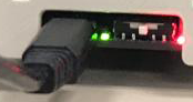
    STEP 1: Connect the AVRISPmkII to your computer. If the internal LED turns green suitable drivers are detected. If not, see “Installing MKII Driver” below.

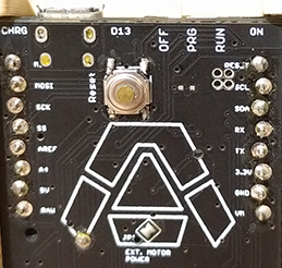
    STEP 2: Connect the 3DoT ICSP breakout to the 3DoT as shown.

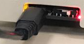
    STEP 3: Connect the AVRISPmkII to the breakout board. Ensure the ribbon cable is oriented to have the red wire closest to the switch and USB port.

    STEP 4: Insert a battery and turn the board ON.

    The external LED will light up green when the board is detected.
    [/av_textblock]

    [av_one_half first min_height=” vertical_alignment=” space=” custom_margin=” margin=’0px’ padding=’0px’ border=” border_color=” radius=’0px’ background_color=” src=” background_position=’top left’ background_repeat=’no-repeat’ animation=” mobile_breaking=” mobile_display=”]
    [av_image src=’https://www.arxterra.com/wp-content/uploads/2018/05/IMG_20190721_193354-min-230×300.jpg’ attachment=’150000′ attachment_size=’medium’ align=’center’ styling=” hover=” link=’lightbox’ target=” caption=” font_size=” appearance=” overlay_opacity=’0.4′ overlay_color=’#000000′ overlay_text_color=’#ffffff’ animation=’no-animation’ admin_preview_bg=”][/av_image]
    [/av_one_half]

    [av_one_half min_height=” vertical_alignment=” space=” custom_margin=” margin=’0px’ padding=’0px’ border=” border_color=” radius=’0px’ background_color=” src=” background_position=’top left’ background_repeat=’no-repeat’ animation=” mobile_breaking=” mobile_display=”]
    [av_image src=’https://www.arxterra.com/wp-content/uploads/2018/05/IMG_20190721_193418-min-235×300.jpg’ attachment=’150001′ attachment_size=’medium’ align=’center’ styling=” hover=” link=’lightbox’ target=” caption=” font_size=” appearance=” overlay_opacity=’0.4′ overlay_color=’#000000′ overlay_text_color=’#ffffff’ animation=’no-animation’ admin_preview_bg=”][/av_image]
    [/av_one_half]

    [av_heading tag=’h4′ padding=’10’ heading=’Installing MKII driver’ color=” style=” custom_font=” size=” subheading_active=” subheading_size=’15’ custom_class=” admin_preview_bg=” av-desktop-hide=” av-medium-hide=” av-small-hide=” av-mini-hide=” av-medium-font-size-title=” av-small-font-size-title=” av-mini-font-size-title=” av-medium-font-size=” av-small-font-size=” av-mini-font-size=”][/av_heading]

    [av_textblock size=” font_color=” color=” av-medium-font-size=” av-small-font-size=” av-mini-font-size=” admin_preview_bg=”]
    If the AVR programmer is not recognized by your computer, the appropriate driver must first be installed. Download the proper driver for the AVR programmer from the web. If the AVRISP MKII driver is being used, it can be downloaded from this link. If the USBtiny AVR Programmer is being used, the driver can be downloaded from this link.

    To configure AVRISP MKII Programmer to work with Arduino IDE (steps to download in section “02 – 1: Arduino IDE Tutorial”), it is necessary to install lib-win32 drivers. Extract the downloaded zip file, then follow the steps below to install AVRISP drivers:

    STEP 1: Disable windows driver signature enforcement by following steps in this tutorial.

    STEP 2:  Plug in the programmer to computer intended for the installation process, then open the “Device Manager”.

    STEP 3:  Right-click on “AVRISP mkII” and click on “Update Driver Software”.
    [/av_textblock]

    [av_image src=’https://www.arxterra.com/wp-content/uploads/2018/05/arduino_136-1030×644.png’ attachment=’140242′ attachment_size=’large’ align=’center’ styling=” hover=” link=’lightbox’ target=” caption=” font_size=” appearance=” overlay_opacity=’0.4′ overlay_color=’#000000′ overlay_text_color=’#ffffff’ animation=’no-animation’ admin_preview_bg=”][/av_image]

    [av_textblock size=” font_color=” color=” av-medium-font-size=” av-small-font-size=” av-mini-font-size=” admin_preview_bg=”]
    STEP 4:  Click on “Browse my computer for driver software”.
    [/av_textblock]

    [av_image src=’https://www.arxterra.com/wp-content/uploads/2018/05/arduino_137.png’ attachment=’140243′ attachment_size=’full’ align=’center’ styling=” hover=” link=’lightbox’ target=” caption=” font_size=” appearance=” overlay_opacity=’0.4′ overlay_color=’#000000′ overlay_text_color=’#ffffff’ animation=’no-animation’ admin_preview_bg=”][/av_image]

    [av_textblock size=” font_color=” color=” av-medium-font-size=” av-small-font-size=” av-mini-font-size=” admin_preview_bg=”]
    STEP 5: Make sure that “Include subfolders” is checked, then click on “Browse”.
    [/av_textblock]

    [av_image src=’https://www.arxterra.com/wp-content/uploads/2018/05/arduino_138.png’ attachment=’140244′ attachment_size=’full’ align=’center’ styling=” hover=” link=’lightbox’ target=” caption=” font_size=” appearance=” overlay_opacity=’0.4′ overlay_color=’#000000′ overlay_text_color=’#ffffff’ animation=’no-animation’ admin_preview_bg=”][/av_image]

    [av_textblock size=” font_color=” color=” av-medium-font-size=” av-small-font-size=” av-mini-font-size=” admin_preview_bg=”]
    STEP 6: Navigate to the extracted folder (i.e. avrispmkii_libusb-win32_1.2.1.0), then click “OK”.
    [/av_textblock]

    [av_image src=’https://www.arxterra.com/wp-content/uploads/2018/05/arduino_139.png’ attachment=’140245′ attachment_size=’full’ align=’center’ styling=” hover=” link=’lightbox’ target=” caption=” font_size=” appearance=” overlay_opacity=’0.4′ overlay_color=’#000000′ overlay_text_color=’#ffffff’ animation=’no-animation’ admin_preview_bg=”][/av_image]

    [av_textblock size=” font_color=” color=” av-medium-font-size=” av-small-font-size=” av-mini-font-size=” admin_preview_bg=”]
    STEP 7: Click on “Let me pick from a list of device drivers on my computer”.
    [/av_textblock]

    [av_image src=’https://www.arxterra.com/wp-content/uploads/2018/05/arduino_138.png’ attachment=’140244′ attachment_size=’full’ align=’center’ styling=” hover=” link=’lightbox’ target=” caption=” font_size=” appearance=” overlay_opacity=’0.4′ overlay_color=’#000000′ overlay_text_color=’#ffffff’ animation=’no-animation’ admin_preview_bg=”][/av_image]

    [av_textblock size=” font_color=” color=” av-medium-font-size=” av-small-font-size=” av-mini-font-size=” admin_preview_bg=”]
    STEP 8: Click on “libusb-win32 devices”.
    [/av_textblock]

    [av_image src=’https://www.arxterra.com/wp-content/uploads/2018/05/arduino_142.png’ attachment=’140247′ attachment_size=’full’ align=’center’ styling=” hover=” link=’lightbox’ target=” caption=” font_size=” appearance=” overlay_opacity=’0.4′ overlay_color=’#000000′ overlay_text_color=’#ffffff’ animation=’no-animation’ admin_preview_bg=”][/av_image]

    [av_textblock size=” font_color=” color=” av-medium-font-size=” av-small-font-size=” av-mini-font-size=” admin_preview_bg=”]
    STEP 10:  Click on “Browse” and locate “AVRISP_mkII.inf” in the “Downloads” folder.
    [/av_textblock]

    [av_image src=’https://www.arxterra.com/wp-content/uploads/2018/05/arduino_143.png’ attachment=’140248′ attachment_size=’full’ align=’center’ styling=” hover=” link=’lightbox’ target=” caption=” font_size=” appearance=” overlay_opacity=’0.4′ overlay_color=’#000000′ overlay_text_color=’#ffffff’ animation=’no-animation’ admin_preview_bg=”][/av_image]

    [av_textblock size=” font_color=” color=” av-medium-font-size=” av-small-font-size=” av-mini-font-size=” admin_preview_bg=”]
    STEP 11: Click “Next” to close and the driver should be successfully installed.
    [/av_textblock]

    [av_image src=’https://www.arxterra.com/wp-content/uploads/2018/05/arduino_144-300×223.png’ attachment=’140249′ attachment_size=’medium’ align=’center’ styling=” hover=” link=’lightbox’ target=” caption=” font_size=” appearance=” overlay_opacity=’0.4′ overlay_color=’#000000′ overlay_text_color=’#ffffff’ animation=’no-animation’ admin_preview_bg=”][/av_image]

    [av_image src=’https://www.arxterra.com/wp-content/uploads/2018/05/arduino_145-300×223.png’ attachment=’140250′ attachment_size=’medium’ align=’center’ styling=” hover=” link=’lightbox’ target=” caption=” font_size=” appearance=” overlay_opacity=’0.4′ overlay_color=’#000000′ overlay_text_color=’#ffffff’ animation=’no-animation’ admin_preview_bg=”][/av_image]

    [av_heading tag=’h4′ padding=’10’ heading=’Writing the Fuse Settings’ color=” style=” custom_font=” size=” subheading_active=” subheading_size=’15’ custom_class=” admin_preview_bg=” av-desktop-hide=” av-medium-hide=” av-small-hide=” av-mini-hide=” av-medium-font-size-title=” av-small-font-size-title=” av-mini-font-size-title=” av-medium-font-size=” av-small-font-size=” av-mini-font-size=”][/av_heading]

    [av_textblock size=” font_color=” color=” av-medium-font-size=” av-small-font-size=” av-mini-font-size=” admin_preview_bg=”]
    Now, setting the correct fuse settings can be done by two methods:
    [/av_textblock]

    [av_heading tag=’h5′ padding=’10’ heading=’Method 1: Using Atmel Studio 7 (Windows Only)’ color=” style=” custom_font=” size=” subheading_active=” subheading_size=’15’ custom_class=” admin_preview_bg=” av-desktop-hide=” av-medium-hide=” av-small-hide=” av-mini-hide=” av-medium-font-size-title=” av-small-font-size-title=” av-mini-font-size-title=” av-medium-font-size=” av-small-font-size=” av-mini-font-size=”][/av_heading]

    [av_textblock size=” font_color=” color=” av-medium-font-size=” av-small-font-size=” av-mini-font-size=” admin_preview_bg=”]
    STEP 1: Open Atmel Studio 7 and click Tools -> Device Programming.
    [/av_textblock]

    [av_image src=’https://www.arxterra.com/wp-content/uploads/2018/05/studio1.png’ attachment=’143864′ attachment_size=’full’ align=’center’ styling=” hover=” link=’lightbox’ target=” caption=” font_size=” appearance=” overlay_opacity=’0.4′ overlay_color=’#000000′ overlay_text_color=’#ffffff’ animation=’no-animation’ admin_preview_bg=”][/av_image]

    [av_textblock size=” font_color=” color=” av-medium-font-size=” av-small-font-size=” av-mini-font-size=” admin_preview_bg=”]
    STEP 2: The following window will appear. The tool to select is the AVRISPmkII. The device to select depends on what microcontroller is being used on your device. In the case of the 3DoT board, you will be selecting the Atmega32U4. You can find it by using the drop down menu or by typing out the name. Ensure the settings are as pictured and click “Apply”.
    [/av_textblock]

    [av_image src=’https://www.arxterra.com/wp-content/uploads/2018/05/studio2.png’ attachment=’143865′ attachment_size=’full’ align=’center’ styling=” hover=” link=’lightbox’ target=” caption=” font_size=” appearance=” overlay_opacity=’0.4′ overlay_color=’#000000′ overlay_text_color=’#ffffff’ animation=’no-animation’ admin_preview_bg=”][/av_image]

    [av_textblock size=” font_color=” color=” av-medium-font-size=” av-small-font-size=” av-mini-font-size=” admin_preview_bg=”]
    STEP 3: If your device connected successfully you should see the following window. Click “Fuses”.
    [/av_textblock]

    [av_image src=’https://www.arxterra.com/wp-content/uploads/2018/05/studio3.png’ attachment=’143866′ attachment_size=’full’ align=’center’ styling=” hover=” link=’lightbox’ target=” caption=” font_size=” appearance=” overlay_opacity=’0.4′ overlay_color=’#000000′ overlay_text_color=’#ffffff’ animation=’no-animation’ admin_preview_bg=”][/av_image]

    [av_textblock size=” font_color=” color=” av-medium-font-size=” av-small-font-size=” av-mini-font-size=” admin_preview_bg=”]
    STEP 4: Set the fuses as follows:

    Extended Fuse: 0xCF

    High fuse: 0xD8

    Low fuse: 0xE2

    and click “Program”. To understand what each fuse setting does, refer to the ATmega32u4 Datasheet.

    A warning may pop up to change to certain fuses. These warnings can be accepted.
    [/av_textblock]

    [av_image src=’https://www.arxterra.com/wp-content/uploads/2018/05/studio4.png’ attachment=’143867′ attachment_size=’full’ align=’center’ styling=” hover=” link=’lightbox’ target=” caption=” font_size=” appearance=” overlay_opacity=’0.4′ overlay_color=’#000000′ overlay_text_color=’#ffffff’ animation=’no-animation’ admin_preview_bg=”][/av_image]

    [av_heading tag=’h5′ padding=’10’ heading=’Method 2: Using avrdude (All platforms)’ color=” style=” custom_font=” size=” subheading_active=” subheading_size=’15’ custom_class=” admin_preview_bg=” av-desktop-hide=” av-medium-hide=” av-small-hide=” av-mini-hide=” av-medium-font-size-title=” av-small-font-size-title=” av-mini-font-size-title=” av-medium-font-size=” av-small-font-size=” av-mini-font-size=”][/av_heading]

    [av_textblock size=” font_color=” color=” av-medium-font-size=” av-small-font-size=” av-mini-font-size=” admin_preview_bg=”]
    STEP 1: Download and install WinAVR.

    ( On Linux run sudo apt-get install avr-libc avrdude binutils-avr gcc-avr srecord )

    ( On OS X install CrossPack and libusb)

    STEP 2: Open Command Prompt (or a terminal window on Linux/OS X). Paste the following command into the command prompt.

    avrdude -c avrispmkII -p m32u4 -P usb -U efuse:w:0xCF:m -U hfuse:w:0xD8:m -U lfuse:w:0xE2:m

    This will configure the fuses to the setting best suited for the 3DoT board.

    To customize the fuse settings, see this calculator for the possible options.
    [/av_textblock]

    [av_heading tag=’h4′ padding=’10’ heading=’Burn Bootloader using Arduino IDE’ color=” style=” custom_font=” size=” subheading_active=” subheading_size=’15’ custom_class=” admin_preview_bg=” av-desktop-hide=” av-medium-hide=” av-small-hide=” av-mini-hide=” av-medium-font-size-title=” av-small-font-size-title=” av-mini-font-size-title=” av-medium-font-size=” av-small-font-size=” av-mini-font-size=”][/av_heading]

    [av_textblock size=” font_color=” color=” av-medium-font-size=” av-small-font-size=” av-mini-font-size=” admin_preview_bg=”]
    STEP 1: Plug in the ICSP socket to the 3DoT board and jumper wires to the proper AVRISP mkII programmer pins. Then switch ON the 3DoT.

    STEP 2: After switching the 3DoT ON, the LED on the AVRISP mkII programmer will change from red to yellow.

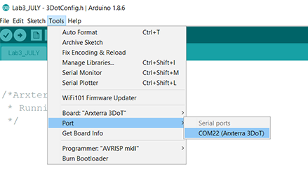
    STEP 3: Open Arduino IDE and go to Tools > Programmer. Make sure “AVR mkII” is selected.
    [/av_textblock]

    [av_image src=’https://www.arxterra.com/wp-content/uploads/2018/05/arduinobootloader1.png’ attachment=’143868′ attachment_size=’full’ align=’center’ styling=” hover=” link=’lightbox’ target=” caption=” font_size=” appearance=” overlay_opacity=’0.4′ overlay_color=’#000000′ overlay_text_color=’#ffffff’ animation=’no-animation’ admin_preview_bg=”][/av_image]

    [av_textblock size=” font_color=” color=” av-medium-font-size=” av-small-font-size=” av-mini-font-size=” admin_preview_bg=”]
    STEP 4: Select “Arxterra 3DoT” from Tools > Board.

    If the Arxterra 3DoT board is not installed in your Arduino IDE, see the “Arduino IDE 3DoT Tutorial”
    [/av_textblock]

    [av_image src=’https://www.arxterra.com/wp-content/uploads/2018/05/bootloader7.png’ attachment=’143871′ attachment_size=’full’ align=’center’ styling=” hover=” link=’lightbox’ target=” caption=” font_size=” appearance=” overlay_opacity=’0.4′ overlay_color=’#000000′ overlay_text_color=’#ffffff’ animation=’no-animation’ admin_preview_bg=”][/av_image]

    [av_textblock size=” font_color=” color=” av-medium-font-size=” av-small-font-size=” av-mini-font-size=” admin_preview_bg=”]
    STEP 5:  Go to Tools > Burn Bootloader.
    [/av_textblock]

    [av_image src=’https://www.arxterra.com/wp-content/uploads/2018/05/arduinobootloader3.png’ attachment=’143869′ attachment_size=’full’ align=’center’ styling=” hover=” link=’lightbox’ target=” caption=” font_size=” appearance=” overlay_opacity=’0.4′ overlay_color=’#000000′ overlay_text_color=’#ffffff’ animation=’no-animation’ admin_preview_bg=”][/av_image]

    [av_textblock size=” font_color=” color=” av-medium-font-size=” av-small-font-size=” av-mini-font-size=” admin_preview_bg=”]
    STEP 6: Ignore the “WARNING” and wait for the Bootloader to be burned.
    [/av_textblock]

    [av_image src=’https://www.arxterra.com/wp-content/uploads/2018/05/arduinobootloader4.png’ attachment=’143870′ attachment_size=’full’ align=’center’ styling=” hover=” link=’lightbox’ target=” caption=” font_size=” appearance=” overlay_opacity=’0.4′ overlay_color=’#000000′ overlay_text_color=’#ffffff’ animation=’no-animation’ admin_preview_bg=”][/av_image]

    [av_hr class=’short’ height=’50’ shadow=’no-shadow’ position=’center’ custom_border=’av-border-thin’ custom_width=’50px’ custom_border_color=” custom_margin_top=’30px’ custom_margin_bottom=’30px’ icon_select=’yes’ custom_icon_color=” icon=’ue808′ font=’entypo-fontello’ admin_preview_bg=”]

  • Tutorial on Fast Pulse Width Modulation

    Tutorial on Fast Pulse Width Modulation

    [av_heading tag=’h2′ padding=’10’ heading=’Tutorial on Fast Pulse Width Modulation’ color=” style=” custom_font=” size=” subheading_active=” subheading_size=’15’ custom_class=” admin_preview_bg=” av-desktop-hide=” av-medium-hide=” av-small-hide=” av-mini-hide=” av-medium-font-size-title=” av-small-font-size-title=” av-mini-font-size-title=” av-medium-font-size=” av-small-font-size=” av-mini-font-size=”][/av_heading]

    [av_textblock size=” font_color=” color=” av-medium-font-size=” av-small-font-size=” av-mini-font-size=” admin_preview_bg=”]

    [/av_textblock]

    [av_textblock size=” font_color=” color=” av-medium-font-size=” av-small-font-size=” av-mini-font-size=” admin_preview_bg=”]
    Many of the labs in this document employ fast pulse width modulation (PWM) as implemented by one or more of the Atmega32U4’s four (4) timer peripheral subsystems. This chapter is included for those developers who are not familiar with fast pulse width modulation and/or the timer peripheral subsystems of the Atmega32U4.
    [/av_textblock]

    [av_heading tag=’h4′ padding=’10’ heading=’Modes of PWM’ color=” style=” custom_font=” size=” subheading_active=” subheading_size=’15’ custom_class=” admin_preview_bg=” av-desktop-hide=” av-medium-hide=” av-small-hide=” av-mini-hide=” av-medium-font-size-title=” av-small-font-size-title=” av-mini-font-size-title=” av-medium-font-size=” av-small-font-size=” av-mini-font-size=”][/av_heading]

    [av_textblock size=” font_color=” color=” av-medium-font-size=” av-small-font-size=” av-mini-font-size=” admin_preview_bg=”]
    Pulse Width Modulation (PWM) is a technique for outputting analog voltage levels using digital means. What this means is that these pins output a square wave signal that oscillates between on and off. This oscillation essentially produces voltage levels between 0 and 5 volts depending on the duty cycle of the signal and is controlled using the “analogWrite(pin, value)” function where ‘pin’ is the pin that you are writing to and ‘value’ is a value between 0 and 255. Inputting the value 0 will result in a square wave with a 0% duty cycle and produce 0V (always off), inputting the value 127 will result in a square wave with a 50% duty cycle and produce 2.5V, while inputting the value 255 will result in square wave with a 100% duty cycle and produce 5V (always on). Any value in between 0 and 255 will result in a duty cycle between 0% and 100% correspondingly. Sample PWM signals produced with varied values can be seen below in Figure 16.1.
    [/av_textblock]

    [av_image src=’https://www.arxterra.com/wp-content/uploads/2018/05/arduino_118.png’ attachment=’140214′ attachment_size=’full’ align=’center’ styling=” hover=” link=’lightbox’ target=” caption=” font_size=” appearance=” overlay_opacity=’0.4′ overlay_color=’#000000′ overlay_text_color=’#ffffff’ animation=’no-animation’ admin_preview_bg=”][/av_image]

    [av_textblock size=” font_color=” color=” av-medium-font-size=” av-small-font-size=” av-mini-font-size=” admin_preview_bg=”]

    Figure 16.1: Values varied for the “analogWrite()” function and their resulting PWM signal.

    [/av_textblock]

    [av_textblock size=” font_color=” color=” av-medium-font-size=” av-small-font-size=” av-mini-font-size=” admin_preview_bg=”]
    PWM has several applications. A few are:

    • Dimming an LED
    • Providing an analog output; if the digital output is filtered,
      it will provide an analog voltage between 0% and 100%.
    • Generating audio signals.
    • Providing variable speed control for motors.
    • Generating a modulated signal, for example, to drive an infrared LED for a remote control.

    Now, there are two main operating modes of PWM: phase-correct PWM and fast PWM. To briefly explain the difference between the two, in phase-correct PWM mode the timer counter counts up and down (generating a triangle wave). When the counter reaches the compare bit, the PWM signal will be high, and when the counter counts back down below the compare bit the PWM signal will be low. Characteristics of phase-correct PWM are that the pulses are wider and that the middle of OCRnA and OCRnB are in alignment (where OCRnA and OCRnB are two separate PWM pins connected to the same timer counter) as shown in Figure 16.2.
    [/av_textblock]

    [av_image src=’https://www.arxterra.com/wp-content/uploads/2018/05/arduino_119-300×184.png’ attachment=’140215′ attachment_size=’medium’ align=’center’ styling=” hover=” link=’lightbox’ target=” caption=” font_size=” appearance=” overlay_opacity=’0.4′ overlay_color=’#000000′ overlay_text_color=’#ffffff’ animation=’no-animation’ admin_preview_bg=”][/av_image]

    [av_textblock size=” font_color=” color=” av-medium-font-size=” av-small-font-size=” av-mini-font-size=” admin_preview_bg=”]

    Figure 16.2: Phase-correct PWM.

    In fast PWM mode, the timer counter counts up and then drastically drops down to zero again (generating a sawtooth wave). When the counter reaches the compare bit, the PWM signal will be high, and when the counter drops back down, the PWM signal will be low. Characteristics of fast PWM are that it is twice as fast, the pulses are narrower, and that the rising edges of OCRnA and OCRnB are in alignment as shown in Figure 16.3.
    [/av_textblock]

    [av_image src=’https://www.arxterra.com/wp-content/uploads/2018/05/arduino_120-300×218.png’ attachment=’140216′ attachment_size=’medium’ align=’center’ styling=” hover=” link=’lightbox’ target=” caption=” font_size=” appearance=” overlay_opacity=’0.4′ overlay_color=’#000000′ overlay_text_color=’#ffffff’ animation=’no-animation’ admin_preview_bg=”][/av_image]

    [av_textblock size=” font_color=” color=” av-medium-font-size=” av-small-font-size=” av-mini-font-size=” admin_preview_bg=”]

    Figure 16.3: Fast PWM.

    Phase-correct PWM is the type that most of the PWM pins on the Arduino operate at, while the only pins that operate using fast PWM are the pin(s) that utilize Timer Counter 0. It is not a good idea to mess with Timer Counter 0, because this is the timer that Arduino uses to create the delay() function. However, this lab will show how to convert all PWM pins in phase-correct mode to fast mode.
    [/av_textblock]

    [av_heading tag=’h4′ padding=’10’ heading=’Fast PWM with the Leonardo’ color=” style=” custom_font=” size=” subheading_active=” subheading_size=’15’ custom_class=” admin_preview_bg=” av-desktop-hide=” av-medium-hide=” av-small-hide=” av-mini-hide=” av-medium-font-size-title=” av-small-font-size-title=” av-mini-font-size-title=” av-medium-font-size=” av-small-font-size=” av-mini-font-size=”][/av_heading]

    [av_textblock size=” font_color=” color=” av-medium-font-size=” av-small-font-size=” av-mini-font-size=” admin_preview_bg=”]

    Note: This Tutorial is focused on Leonardo, needs to be refocused for 3Dot

    For learning PWM modes for the 3DoT, begin with using the Arduino Leonardo since it uses the same microcontroller, the Atmega32u4. The reason this lesson will be taught on the Leonardo rather than the 3DoT is that the Leonardo has header pins which we can easily access each digital output.

    There are seven PWM pins on the Leonardo. These are pins 3, 5, 6, 9, 10, 11, and 13. These pins are easily identifiable as digital pins capable of PWM by the tilde symbol (~) right next to each of these numbers. These pins belong to the following timer counters, and are pre-programmed to operate in the following PWM modes seen in Table 02 below. The digital pins that use Timer 0 and are in fast PWM mode have a frequency that is twice as fast as the frequency of the pins that are in phase-correct mode, which is consistent with what has previously been explained.
    [/av_textblock]

    [av_image src=’https://www.arxterra.com/wp-content/uploads/2018/05/arduino_121.png’ attachment=’140217′ attachment_size=’full’ align=’center’ styling=” hover=” link=’lightbox’ target=” caption=” font_size=” appearance=” overlay_opacity=’0.4′ overlay_color=’#000000′ overlay_text_color=’#ffffff’ animation=’no-animation’ admin_preview_bg=”][/av_image]

    [av_textblock size=” font_color=” color=” av-medium-font-size=” av-small-font-size=” av-mini-font-size=” admin_preview_bg=”]

    Table 16.1: PWM modes for each digital pin on the Arduino Leonardo.

    [/av_textblock]

    [av_textblock size=” font_color=” color=” av-medium-font-size=” av-small-font-size=” av-mini-font-size=” admin_preview_bg=”]
    First, set up a test code to verify that each pin on your Arduino Leonardo really produces the frequencies specified above. Download the following code.
    [/av_textblock]

    [av_button label=’FastPWM Example Code’ link=’manually,https://github.com/rdaly93/Fast_PWM/blob/master/FastPWM.ino’ link_target=” size=’medium’ position=’center’ icon_select=’yes’ icon=’ue82d’ font=’entypo-fontello’ color=’theme-color’ custom_bg=’#444444′ custom_font=’#ffffff’ admin_preview_bg=”]

    [av_textblock size=” font_color=” color=” av-medium-font-size=” av-small-font-size=” av-mini-font-size=” admin_preview_bg=”]
    In this test code all the PWM pins on the Leonardo are set to output a PWM signal. Furthermore, Analog Pin 0 (though any I/O pin could be used) is set as an input to read the frequency of generated PWM pins. To test the frequency of each pin, simply start with connecting pin 3 to A0 as shown below in Figure 16.4.
    [/av_textblock]

    [av_image src=’https://www.arxterra.com/wp-content/uploads/2018/05/arduino_122-300×259.png’ attachment=’140219′ attachment_size=’medium’ align=’center’ styling=” hover=” link=’lightbox’ target=” caption=” font_size=” appearance=” overlay_opacity=’0.4′ overlay_color=’#000000′ overlay_text_color=’#ffffff’ animation=’no-animation’ admin_preview_bg=”][/av_image]

    [av_textblock size=” font_color=” color=” av-medium-font-size=” av-small-font-size=” av-mini-font-size=” admin_preview_bg=”]

    Figure 16.4: Connect pin 3 to A0.

    Make sure the board is plugged in and the proper board and COM port are chosen in Arduino IDE as shown in Figure  16.5:
    [/av_textblock]

    [av_image src=’https://www.arxterra.com/wp-content/uploads/2018/05/arduino_123-300×169.png’ attachment=’140220′ attachment_size=’medium’ align=’center’ styling=” hover=” link=’lightbox’ target=” caption=” font_size=” appearance=” overlay_opacity=’0.4′ overlay_color=’#000000′ overlay_text_color=’#ffffff’ animation=’no-animation’ admin_preview_bg=”][/av_image]

    [av_image src=’https://www.arxterra.com/wp-content/uploads/2018/05/arduino_124-300×169.png’ attachment=’140221′ attachment_size=’medium’ align=’center’ styling=” hover=” link=’lightbox’ target=” caption=” font_size=” appearance=” overlay_opacity=’0.4′ overlay_color=’#000000′ overlay_text_color=’#ffffff’ animation=’no-animation’ admin_preview_bg=”][/av_image]

    [av_textblock size=” font_color=” color=” av-medium-font-size=” av-small-font-size=” av-mini-font-size=” admin_preview_bg=”]

    Figure 16.5: Choosing the correct board and COM port.  

    Upload the code to the board and open the “Serial Monitor” window as shown below in Figure 16.6:
    [/av_textblock]

    [av_image src=’https://www.arxterra.com/wp-content/uploads/2018/05/arduino_125-300×169.png’ attachment=’140222′ attachment_size=’medium’ align=’center’ styling=” hover=” link=’lightbox’ target=” caption=” font_size=” appearance=” overlay_opacity=’0.4′ overlay_color=’#000000′ overlay_text_color=’#ffffff’ animation=’no-animation’ admin_preview_bg=”][/av_image]

    [av_image src=’https://www.arxterra.com/wp-content/uploads/2018/05/arduino_126.png’ attachment=’140223′ attachment_size=’full’ align=’center’ styling=” hover=” link=’lightbox’ target=” caption=” font_size=” appearance=” overlay_opacity=’0.4′ overlay_color=’#000000′ overlay_text_color=’#ffffff’ animation=’no-animation’ admin_preview_bg=”][/av_image]

    [av_textblock size=” font_color=” color=” av-medium-font-size=” av-small-font-size=” av-mini-font-size=” admin_preview_bg=”]

    Figure 16.6: Opening the “Serial Monitor” window

    Now, if pin 3 was started with, the frequency displayed in the Serial Monitor should be around 976 Hz, which is consistent with Table 02. Next, move on down the list of the PWM pins (5, 6, 9, 10, 11, and 13) and continue to measure the frequency of each pin. Verify that the recorded data matches up with Table 02. Please note that this Arduino frequency reader is not 100% accurate so the experimental values will be slightly off.

    Next, begin converting each pin that is operating in phase-correct PWM mode to fast PWM mode. First, start with Timer 1, which generates PWM signals for pins 9 and 10. In Timer Counter 1, the PWM operating mode is controlled in the TCCR1A and TCCR1B registers as shown in Figure 16.7.
    [/av_textblock]

    [av_image src=’https://www.arxterra.com/wp-content/uploads/2018/05/arduino_127.png’ attachment=’140224′ attachment_size=’full’ align=’center’ styling=” hover=” link=’lightbox’ target=” caption=” font_size=” appearance=” overlay_opacity=’0.4′ overlay_color=’#000000′ overlay_text_color=’#ffffff’ animation=’no-animation’ admin_preview_bg=”][/av_image]

    [av_textblock size=” font_color=” color=” av-medium-font-size=” av-small-font-size=” av-mini-font-size=” admin_preview_bg=”]

    Figure 16.7: Timer counter 1 PWM operating modes controlled by registers “TCCR1A” and “TCCR1B”.

    Each pin is important and has a specific purpose but only focus on the ones with PWM operating modes which is controlled by the “WGM12”, “WGM11”, and “WGM10” bits. Table 16.2 below shows what each bit should be set to in order to achieve various PWM operating modes.
    [/av_textblock]

    [av_image src=’https://www.arxterra.com/wp-content/uploads/2018/05/arduino_128.png’ attachment=’140225′ attachment_size=’full’ align=’center’ styling=” hover=” link=’lightbox’ target=” caption=” font_size=” appearance=” overlay_opacity=’0.4′ overlay_color=’#000000′ overlay_text_color=’#ffffff’ animation=’no-animation’ admin_preview_bg=”][/av_image]

    [av_textblock size=” font_color=” color=” av-medium-font-size=” av-small-font-size=” av-mini-font-size=” admin_preview_bg=”]

    Table 16.1: Pin values and corresponding PWM operating modes.

    To achieve fast PWM, “WGM12” should be set high to ‘1’. The easiest way to do this is to use the “inbuild _BV()” function in Arduino IDE. Copy and paste the following code at the end of “setup()”. Through using the OR command, set the “WGM12” bit in the TCRR1B register high without altering any of the other bits.

    TCCR1B = TCCR1B | _BV(WGM12);   // Set fast PWM for Timer Counter 1

    Next, convert Timer 3, which controls pin 5, to fast PWM mode. This is very easy and similar to Timer 1. Copy and paste the following code below the line at the end of “setup()”.

    TCCR3B = TCCR3B | _BV(WGM32);   // Set fast PWM for Timer Counter 3

    Last, converting Timer 4, which controls pins 6 and 13, is a bit different. Its PWM functionality is controlled through the TCCR4D register as follows in Table 16.3:
    [/av_textblock]

    [av_image src=’https://www.arxterra.com/wp-content/uploads/2018/05/arduino_129.png’ attachment=’140226′ attachment_size=’full’ align=’center’ styling=” hover=” link=’lightbox’ target=” caption=” font_size=” appearance=” overlay_opacity=’0.4′ overlay_color=’#000000′ overlay_text_color=’#ffffff’ animation=’no-animation’ admin_preview_bg=”][/av_image]

    [av_textblock size=” font_color=” color=” av-medium-font-size=” av-small-font-size=” av-mini-font-size=” admin_preview_bg=”]

    Table 16.3: Values to convert Timer 4 using the “TCCR4D” register.

    So to make Timer 4 operate in fast PWM mode, clear the WGM41 and WGM40 bits in the TCCR4D register shown in Figure 16.8:
    [/av_textblock]

    [av_image src=’https://www.arxterra.com/wp-content/uploads/2018/05/arduino_130.png’ attachment=’140227′ attachment_size=’full’ align=’center’ styling=” hover=” link=’lightbox’ target=” caption=” font_size=” appearance=” overlay_opacity=’0.4′ overlay_color=’#000000′ overlay_text_color=’#ffffff’ animation=’no-animation’ admin_preview_bg=”][/av_image]

    [av_textblock size=” font_color=” color=” av-medium-font-size=” av-small-font-size=” av-mini-font-size=” admin_preview_bg=”]

    Figure 16.8: Bits of “TCCR4D” register.

    This is easily achieved through using the AND command with zeros in the place of bits ‘0’ and ‘1’ and ones for bits 7:2 in order to not manipulate any of the other bits. Copy and paste the following code at the end of “setup()”.

    TCCR4D = TCCR4D & 0b11111100;   // Set fast PWM for Timer Counter 4

    Run the code, open the “Serial Monitor”, and measure the frequency of each pin. You should find that the frequency of pins 5, 6, 9, 10, and 13 have doubled. Again, this is from converting each pin from operating in phase-correct mode to fast mode, which operates at twice the speed. Verify that these pins now generate PWM signals with a frequency of 976 Hz.
    [/av_textblock]

    [av_hr class=’short’ height=’50’ shadow=’no-shadow’ position=’center’ custom_border=’av-border-thin’ custom_width=’50px’ custom_border_color=” custom_margin_top=’30px’ custom_margin_bottom=’30px’ icon_select=’yes’ custom_icon_color=” icon=’ue808′ font=’entypo-fontello’ admin_preview_bg=”]

    [av_button label=’Continue to Troubleshooting & Bootloader Burning’ link=’manually,https://www.arxterra.com/troubleshooting-bootloader-burning/’ link_target=” size=’large’ position=’center’ icon_select=’yes-right-icon’ icon=’ue87d’ font=’entypo-fontello’ color=’theme-color’ custom_bg=’#444444′ custom_font=’#ffffff’ admin_preview_bg=”]

  • Programming Your Robot & Custom Telemetry

    Programming Your Robot & Custom Telemetry

    [av_textblock size=” font_color=” color=” av-medium-font-size=” av-small-font-size=” av-mini-font-size=” admin_preview_bg=”]

    WARNING

    Some of the information on this page is outdated, from a time when the ArxRobot Library was still named the “Robot3DoTBoard” Library. Proceed at your own risk.

    [/av_textblock]

    [av_heading tag=’h2′ padding=’10’ heading=’Programming Your Robot’ color=” style=” custom_font=” size=” subheading_active=” subheading_size=’15’ custom_class=” admin_preview_bg=” av-desktop-hide=” av-medium-hide=” av-small-hide=” av-mini-hide=” av-medium-font-size-title=” av-small-font-size-title=” av-mini-font-size-title=” av-medium-font-size=” av-small-font-size=” av-mini-font-size=”][/av_heading]

    [av_textblock size=” font_color=” color=” av-medium-font-size=” av-small-font-size=” av-mini-font-size=” admin_preview_bg=”]

    [/av_textblock]

    [av_textblock size=” font_color=” color=” av-medium-font-size=” av-small-font-size=” av-mini-font-size=” admin_preview_bg=”]
    This chapters looks at 3DoT programming from a developer’s perspective. Specifically, this material is intended for developers interested in extending the capabilities of the 3DoT Library. For example how to implement a Mars rover with 6 DC motors in place of 2 DC motors assumed by the software. Before we begin you may want to review Arxterra’s three operating modes as described in “Arxterra Operating Modes.
    [/av_textblock]

    [av_heading tag=’h3′ padding=’10’ heading=’How to Override the Built in Move Command’ color=” style=” custom_font=” size=” subheading_active=” subheading_size=’15’ custom_class=” admin_preview_bg=” av-desktop-hide=” av-medium-hide=” av-small-hide=” av-mini-hide=” av-medium-font-size-title=” av-small-font-size-title=” av-mini-font-size-title=” av-medium-font-size=” av-small-font-size=” av-mini-font-size=”][/av_heading]

    [av_textblock size=” font_color=” color=” av-medium-font-size=” av-small-font-size=” av-mini-font-size=” admin_preview_bg=”]

    This example can be easily extended to allow the control of six-wheel rovers, like our mini-sojourner.

    The built-in MOVE command as the name implies, is used when you want to move your robot. This command assumes a two wheel-caster or track robot. If you are building a four wheel car where the front wheels are turned with a servo or a six (6) rover, like our mini-sojourner Mars rover, you will need to override this command.

    Step 1: If you have not done so already download the code for Robot_3DoT_TeleComm (see Section “01 – 5: Sample Scripts”), rename it Robot_3Dot_Blink, and open it in the Arduino IDE. 

    The “MOVE” command is defined as command ID 0x01 in the Configure.h file.

    In the Robot_3DoT_Telecom example, this command is overridden and linked to the “moveHandler” subroutine located within the main file Robot_3Dot_Telecomm by the C callback statement:

    A placeholder “moveHandler” subroutine is included with the example script.
    [/av_textblock]

    [av_image src=’https://www.arxterra.com/wp-content/uploads/2018/05/arduino_91.png’ attachment=’140088′ attachment_size=’full’ align=’center’ styling=” hover=” link=’lightbox’ target=” caption=” font_size=” appearance=” overlay_opacity=’0.4′ overlay_color=’#000000′ overlay_text_color=’#ffffff’ animation=’no-animation’ admin_preview_bg=”][/av_image]

    [av_textblock size=” font_color=” color=” av-medium-font-size=” av-small-font-size=” av-mini-font-size=” admin_preview_bg=”]

    WARNING

    This and other example handlers include Serial write instructions which can be helpful during testing. These instructions should be deleted or disabled with a block comment (/* */) after testing is completed. Failure to do so will drastically slow the MCU performance and may result in loss-of-signal and other unexpected problems.

    Step 2: For this example, I want to maintain the functionality of the built-in move instruction. To accomplish this, two motor classes need to be created. Add these two lines of code after defining the “BLINK” and “SERVO” command IDs. These will correspond to Motor A and Motor B on the 3DoT board. To better understand why these motor classes are generated, review the Motor.h and Motor.cpp files found in the 3DoT library.
    [/av_textblock]

    [av_image src=’https://www.arxterra.com/wp-content/uploads/2018/05/arduino_92.png’ attachment=’140089′ attachment_size=’full’ align=’center’ styling=” hover=” link=” target=” caption=” font_size=” appearance=” overlay_opacity=’0.4′ overlay_color=’#000000′ overlay_text_color=’#ffffff’ animation=’no-animation’ admin_preview_bg=”][/av_image]

    [av_textblock size=” font_color=” color=” av-medium-font-size=” av-small-font-size=” av-mini-font-size=” admin_preview_bg=”]
    Step 3: Next, each motor will need to be initialized to their respective driver IC pins on the microcontroller. Each motor will use three pins on the TB6612FNG for control: two for direction control and one for speed control. Conveniently, these pins are already defined in the Configure.h file in the 3Dot library. To initialize these pins for control of these motors, add the following lines of code in “setup()”of the  Robot_3Dot_TeleComm file:
    [/av_textblock]

    [av_image src=’https://www.arxterra.com/wp-content/uploads/2018/05/arduino_93.png’ attachment=’140090′ attachment_size=’full’ align=’center’ styling=” hover=” link=” target=” caption=” font_size=” appearance=” overlay_opacity=’0.4′ overlay_color=’#000000′ overlay_text_color=’#ffffff’ animation=’no-animation’ admin_preview_bg=”][/av_image]

    [av_textblock size=” font_color=” color=” av-medium-font-size=” av-small-font-size=” av-mini-font-size=” admin_preview_bg=”]
    Step 4: The “MOVE” command can now be programmed. Write the following code in the “moveHandler.”
    [/av_textblock]

    [av_image src=’https://www.arxterra.com/wp-content/uploads/2018/05/arduino_94.png’ attachment=’140091′ attachment_size=’full’ align=’center’ styling=” hover=” link=” target=” caption=” font_size=” appearance=” overlay_opacity=’0.4′ overlay_color=’#000000′ overlay_text_color=’#ffffff’ animation=’no-animation’ admin_preview_bg=”][/av_image]

    [av_textblock size=” font_color=” color=” av-medium-font-size=” av-small-font-size=” av-mini-font-size=” admin_preview_bg=”]
    Step 5: Finally, our new move handler can be tested using the ArxRobot application or using CoolTerm. Turn off the 3DoT board and connect the motors as shown in Figure 15.1.
    [/av_textblock]

    [av_image src=’https://www.arxterra.com/wp-content/uploads/2018/05/arduino_95-1030×513.png’ attachment=’140092′ attachment_size=’large’ align=’center’ styling=” hover=” link=” target=” caption=” font_size=” appearance=” overlay_opacity=’0.4′ overlay_color=’#000000′ overlay_text_color=’#ffffff’ animation=’no-animation’ admin_preview_bg=”][/av_image]

    [av_textblock size=” font_color=” color=” av-medium-font-size=” av-small-font-size=” av-mini-font-size=” admin_preview_bg=”]

    Figure 15.1: Motor connection location on the 3DoT board.

    [/av_textblock]

    [av_textblock size=” font_color=” color=” av-medium-font-size=” av-small-font-size=” av-mini-font-size=” admin_preview_bg=”]
    Step 6: Turn on the 3DoT board, upload the newly created code, open CoolTerm, connect the board, and open the “Send String” window.  Ok, that may be more like 5 steps.

    Step 7: Input the command string shown below. Keep in mind, the order of the packet ID, packet length, command ID, parameters, and LRC byte is important. In this command string moving from left to right: A5 represents the packet ID, 05 represents the packet length (command ID + number of parameters), 01  represents the MOVE command ID, 01 represents the forward direction of motor A, 80 represents motor A operating at half speed (0x80 is 128 in decimal which is half of 255, the maximum value for PWM), 01 represents the forward direction of motor B, 80 represents motor B operating at half speed, and A1 represents the LRC byte. Send the command packet string and verify that both motors A and B are spinning forward. If the motors are not spinning forward, there could be a possible polarity issue. Simply swap the wiring connection in order to make the motor spin in reverse.
    [/av_textblock]

    [av_image src=’https://www.arxterra.com/wp-content/uploads/2018/05/arduino_96.png’ attachment=’140093′ attachment_size=’full’ align=’center’ styling=” hover=” link=’lightbox’ target=” caption=” font_size=” appearance=” overlay_opacity=’0.4′ overlay_color=’#000000′ overlay_text_color=’#ffffff’ animation=’no-animation’ admin_preview_bg=”][/av_image]

    [av_textblock size=” font_color=” color=” av-medium-font-size=” av-small-font-size=” av-mini-font-size=” admin_preview_bg=”]

    Figure 15.2: Send Move command packet from CoolTerm.

    [/av_textblock]

    [av_textblock size=” font_color=” color=” av-medium-font-size=” av-small-font-size=” av-mini-font-size=” admin_preview_bg=”]
    From experience, when using the “MOVE” command, it may be easier to set the speed to a fixed value since the direction pad on the Arxterra control panel (which uses the “MOVE” command) only controls the direction of the motors, not the speed. If the robot operates at a fixed speed, fixed PWM values can be put in the code. For example:

    This would be more practical when implementing the “MOVE” command on Arxterra. When testing the code in CoolTerm, remove the hex byte for parameter ‘3’ since it is unused, while the hex byte for parameter ‘1’ does not matter. Nevertheless, it is important to keep the direction as parameters ‘0’ and ‘2’ since this is what is used for the direction pad on Arxterra.

    Furthermore, now is a good time to explain that while commands for each motor to brake can be created manually using 0x03 as the direction hex byte, the Motor.cpp file in the 3DoT library defines a brake function. The following code will stop the motors:
    [/av_textblock]

    [av_image src=’https://www.arxterra.com/wp-content/uploads/2018/05/arduino_97.png’ attachment=’140094′ attachment_size=’full’ align=’left’ styling=” hover=” link=” target=” caption=” font_size=” appearance=” overlay_opacity=’0.4′ overlay_color=’#000000′ overlay_text_color=’#ffffff’ animation=’no-animation’ admin_preview_bg=”][/av_image]

    [av_textblock size=” font_color=” color=” av-medium-font-size=” av-small-font-size=” av-mini-font-size=” admin_preview_bg=”]
    Try creating a command to turn motorA on for 5 seconds using “motorA.go()” in conjunction with “delay()” and “motorA.brake”. Repeat the process for motorB.
    [/av_textblock]

    [av_button label=’Custom command program Guide – Example’ link=’manually,https://www.arxterra.com/goliath-fall-2017-app-directed-rc-record-and-playback/’ link_target=” size=’large’ position=’center’ icon_select=’yes’ icon=’ue8c9′ font=’entypo-fontello’ color=’theme-color’ custom_bg=’#444444′ custom_font=’#ffffff’ admin_preview_bg=”]

    [av_heading tag=’h4′ padding=’10’ heading=’How to Program a Rover’ color=” style=” custom_font=” size=” subheading_active=” subheading_size=’15’ custom_class=” admin_preview_bg=” av-desktop-hide=” av-medium-hide=” av-small-hide=” av-mini-hide=” av-medium-font-size-title=” av-small-font-size-title=” av-mini-font-size-title=” av-medium-font-size=” av-small-font-size=” av-mini-font-size=”][/av_heading]

    [av_textblock size=” font_color=” color=” av-medium-font-size=” av-small-font-size=” av-mini-font-size=” admin_preview_bg=”]
    To implement a rover you would need to add a 3DoT shield with two additional motor control chips – 6 motors total. For this class of robot, you may want to write a software slip differential drive program. Communications from the 3DoT board to the shield is implemented as an I2C interface. Software communications for this serial interface protocol is implemented by the Arduino using the “wire” library.
    [/av_textblock]

    [av_heading tag=’h3′ padding=’10’ heading=’How the 3DoT Battery Level Circuit Works’ color=” style=” custom_font=” size=” subheading_active=” subheading_size=’15’ custom_class=” admin_preview_bg=” av-desktop-hide=” av-medium-hide=” av-small-hide=” av-mini-hide=” av-medium-font-size-title=” av-small-font-size-title=” av-mini-font-size-title=” av-medium-font-size=” av-small-font-size=” av-mini-font-size=”][/av_heading]

    [av_textblock size=” font_color=” color=” av-medium-font-size=” av-small-font-size=” av-mini-font-size=” admin_preview_bg=”]
    In the previous sections, we have looked at adding custom command handlers. In this and the next section, we look at how to implement telemetry channels. This example adds the BATTERY_ID telemetry channel to an Arduino Uno. This channel is hardwired into the 3DoT board and when the 3DoT board is connected to Arxterra, this data stream is automatically sent to the ArxRobot application. Consequently, to show how the channel works we will need to use an Arduino Uno in place of the 3DoT board.

    In the Configure.h file, the microcontroller is programmed to read the battery level from pin A5 as shown below:
    [/av_textblock]

    [av_image src=’https://www.arxterra.com/wp-content/uploads/2018/05/arduino_109.png’ attachment=’140106′ attachment_size=’full’ align=’left’ styling=” hover=” link=” target=” caption=” font_size=” appearance=” overlay_opacity=’0.4′ overlay_color=’#000000′ overlay_text_color=’#ffffff’ animation=’no-animation’ admin_preview_bg=”][/av_image]

    [av_textblock size=” font_color=” color=” av-medium-font-size=” av-small-font-size=” av-mini-font-size=” admin_preview_bg=”]
    Step 1: Connect a potentiometer to the Arduino Uno with the two outer pins connected to 5V and GND, while the middle pin is connected to A5 as shown in Figure 15.4. In this circuit, the potentiometer is acting as a voltage divider to divide the 5V between the two variable resistors embedded in the potentiometer. As the potentiometer is turned to the right, the voltage output will increase and decrease as it is turned to the left.
    [/av_textblock]

    [av_image src=’https://www.arxterra.com/wp-content/uploads/2018/05/arduino_110.png’ attachment=’140107′ attachment_size=’full’ align=’center’ styling=” hover=” link=” target=” caption=” font_size=” appearance=” overlay_opacity=’0.4′ overlay_color=’#000000′ overlay_text_color=’#ffffff’ animation=’no-animation’ admin_preview_bg=”][/av_image]

    [av_textblock size=” font_color=” color=” av-medium-font-size=” av-small-font-size=” av-mini-font-size=” admin_preview_bg=”]

    Figure 15.4: Fritzing diagram of potentiometer connected to the Arduino Uno.

    [/av_textblock]

    [av_textblock size=” font_color=” color=” av-medium-font-size=” av-small-font-size=” av-mini-font-size=” admin_preview_bg=”]
    Step 2: Upload “Robot_3Dot_TeleComm” to the Arduino Uno and open CoolTerm. Select the “View Hex” option. As soon as the board is connected, two telemetry strings should appear. The first string is for the battery level and the second is for the motor current.

    Step 3: Select “Clear Data” to clear existing data.

    Step 4: The potentiometer should be dialed to the left and slowly turned to the right. The battery level telemetry will continually update as the simulated battery level changes (potentiometer). The battery levels are shown here.
    [/av_textblock]

    [av_image src=’https://www.arxterra.com/wp-content/uploads/2018/05/arduino_111-1030×85.png’ attachment=’140108′ attachment_size=’large’ align=’center’ styling=” hover=” link=” target=” caption=” font_size=” appearance=” overlay_opacity=’0.4′ overlay_color=’#000000′ overlay_text_color=’#ffffff’ animation=’no-animation’ admin_preview_bg=”][/av_image]

    [av_textblock size=” font_color=” color=” av-medium-font-size=” av-small-font-size=” av-mini-font-size=” admin_preview_bg=”]

    Figure 15.5: Output from CoolTerm of potentiometer connected to the Arduino Uno.

    [/av_textblock]

    [av_textblock size=” font_color=” color=” av-medium-font-size=” av-small-font-size=” av-mini-font-size=” admin_preview_bg=”]
    The first byte, “CA”, is the packet ID, the second byte, “03”, is the packet length, the third byte, “06”, is the telemetry ID, the fourth byte, “00”, is an empty parameter, the fifth byte, “07”, is the parameter desired which shows the battery level in hex. The last byte, “C8”, is the LRC byte.

    As shown above, when the potentiometer is turned from left to right, the following parameter values were achieved: {0x07, 0x14, 0x1A, 0x3D, 0x54, 0x59, 0x5E, and 0x63}. Translating these hex values to decimal: {7, 20, 26, 61, 84, 89, 94, and 99}. These values represent the battery level percentage. So the “battery” started at 7% and “charged” to 99%.
    [/av_textblock]

    [av_heading tag=’h2′ padding=’10’ heading=’Custom Telemetry’ color=” style=” custom_font=” size=” subheading_active=” subheading_size=’15’ custom_class=” admin_preview_bg=” av-desktop-hide=” av-medium-hide=” av-small-hide=” av-mini-hide=” av-medium-font-size-title=” av-small-font-size-title=” av-mini-font-size-title=” av-medium-font-size=” av-small-font-size=” av-mini-font-size=”][/av_heading]

    [av_textblock size=” font_color=” color=” av-medium-font-size=” av-small-font-size=” av-mini-font-size=” admin_preview_bg=”]
    In this section, we will go over the custom telemetry example provided in Robot_3Dot_TeleComm example script.

    Step 1: The first step is to instantiate (“build”) a packet object named motor PWM and initialize its properties. MOTOR2_CURRENT_ID is a pre-defined telemetry channel equal to 0x02 as defined in the Configure.h text file.
    [/av_textblock]

    [av_image src=’https://www.arxterra.com/wp-content/uploads/2018/05/arduino_112.png’ attachment=’140109′ attachment_size=’full’ align=’left’ styling=” hover=” link=” target=” caption=” font_size=” appearance=” overlay_opacity=’0.4′ overlay_color=’#000000′ overlay_text_color=’#ffffff’ animation=’no-animation’ admin_preview_bg=”][/av_image]

    [av_textblock size=” font_color=” color=” av-medium-font-size=” av-small-font-size=” av-mini-font-size=” admin_preview_bg=”]
    Step 2 (optional): Along with setting the telemetry ID property, the motorPWM constructor initializes both the “accuracy” and “samplePeriod” properties to their default values of 2 DN (digital number) and 1000 ms (1 second) respectively. These values should work for most robot application and no further action is needed.  In this “optional” step, these default values are changed to 1 DN  and 500 ms (0.5 seconds). Again, do not override the program’s default values unless required by your project.
    [/av_textblock]

    [av_image src=’https://www.arxterra.com/wp-content/uploads/2018/05/arduino_113.png’ attachment=’140110′ attachment_size=’full’ align=’left’ styling=” hover=” link=” target=” caption=” font_size=” appearance=” overlay_opacity=’0.4′ overlay_color=’#000000′ overlay_text_color=’#ffffff’ animation=’no-animation’ admin_preview_bg=”][/av_image]

    [av_textblock size=” font_color=” color=” av-medium-font-size=” av-small-font-size=” av-mini-font-size=” admin_preview_bg=”]
    Step 3: Next, within “loop()” code segment, the sensor data is read and if the sampling criteria are met (change in DN or sample period) then a telemetry packet is sent. In the example below the “#if” conditional-compilation directive (also known as a preprocessor directive)  is chosen if a board with an ATmega32u4 (e.g., 3Dot, Lilypad USB, and Leonardo) is being used and the “#else” directive is chosen if the Uno is being used. Below demonstrates using the Uno.
    [/av_textblock]

    [av_image src=’https://www.arxterra.com/wp-content/uploads/2018/05/arduino_114.png’ attachment=’140111′ attachment_size=’full’ align=’center’ styling=” hover=” link=” target=” caption=” font_size=” appearance=” overlay_opacity=’0.4′ overlay_color=’#000000′ overlay_text_color=’#ffffff’ animation=’no-animation’ admin_preview_bg=”][/av_image]

    [av_textblock size=” font_color=” color=” av-medium-font-size=” av-small-font-size=” av-mini-font-size=” admin_preview_bg=”]

    Figure 15.6: Loop code segment from Robot_3Dot_TeleComm.

    [/av_textblock]

    [av_heading tag=’h3′ padding=’10’ heading=’Using the UNO’ color=” style=” custom_font=” size=” subheading_active=” subheading_size=’15’ custom_class=” admin_preview_bg=” av-desktop-hide=” av-medium-hide=” av-small-hide=” av-mini-hide=” av-medium-font-size-title=” av-small-font-size-title=” av-mini-font-size-title=” av-medium-font-size=” av-small-font-size=” av-mini-font-size=”][/av_heading]

    [av_textblock size=” font_color=” color=” av-medium-font-size=” av-small-font-size=” av-mini-font-size=” admin_preview_bg=”]
    Step 4: Rather than sending a command to the motors to read the telemetry, it may be easier to manually code them for the time being. Just do not forget to remove this code later. If the Uno is being used, put code to analogWrite to pin 5.
    [/av_textblock]

    [av_image src=’https://www.arxterra.com/wp-content/uploads/2018/05/arduino_115.png’ attachment=’140112′ attachment_size=’full’ align=’left’ styling=” hover=” link=” target=” caption=” font_size=” appearance=” overlay_opacity=’0.4′ overlay_color=’#000000′ overlay_text_color=’#ffffff’ animation=’no-animation’ admin_preview_bg=”][/av_image]

    [av_textblock size=” font_color=” color=” av-medium-font-size=” av-small-font-size=” av-mini-font-size=” admin_preview_bg=”]
    Without getting into the details of Pulse Width Modulation (PWM), the Arduino implements this instruction by setting the Timer 0 Output Compare Register B (0CR0B) equal to 200 (Hexadecimal C8). When Timer 0 counts up to 200 the output of Arduino digital pin 5 is cleared. Please reference Figure 15.7 for all the pins on the Uno and to which timer output pin they are mapped.
    [/av_textblock]

    [av_image src=’https://www.arxterra.com/wp-content/uploads/2018/05/arduino_116.png’ attachment=’140113′ attachment_size=’full’ align=’center’ styling=” hover=” link=’lightbox’ target=” caption=” font_size=” appearance=” overlay_opacity=’0.4′ overlay_color=’#000000′ overlay_text_color=’#ffffff’ animation=’no-animation’ admin_preview_bg=”][/av_image]

    [av_textblock size=” font_color=” color=” av-medium-font-size=” av-small-font-size=” av-mini-font-size=” admin_preview_bg=”]

    Figure 15.7: Arduino UNO timers and corresponding output pins.

    [/av_textblock]

    [av_textblock size=” font_color=” color=” av-medium-font-size=” av-small-font-size=” av-mini-font-size=” admin_preview_bg=”]
    The code within the “#else” block reads Timer 0 Output Compare Register B (0CR0B) and sets variable  “pwm_reading” equal to this value. This register value is then sent as an argument to the “sendSensor()” method.  Ultimately, the is packetized and set to via USB to the PC.

    Step 5: To view this packet, open CoolTerm, connect the board, and View Hex. A similar reading as shown in Figure 15.8 should appear.
    [/av_textblock]

    [av_image src=’https://www.arxterra.com/wp-content/uploads/2018/05/arduino_117.png’ attachment=’140114′ attachment_size=’full’ align=’left’ styling=” hover=” link=” target=” caption=” font_size=” appearance=” overlay_opacity=’0.4′ overlay_color=’#000000′ overlay_text_color=’#ffffff’ animation=’no-animation’ admin_preview_bg=”][/av_image]

    [av_textblock size=” font_color=” color=” av-medium-font-size=” av-small-font-size=” av-mini-font-size=” admin_preview_bg=”]
    Figure 15.8: Telemetry sequence showing value of the 0CR0B register.
    [/av_textblock]

    [av_textblock size=” font_color=” color=” av-medium-font-size=” av-small-font-size=” av-mini-font-size=” admin_preview_bg=”]
    In Figure 15.8, the first telemetry sequence is the battery telemetry, and can be disregarded for now. The second telemetry sequence, which is boxed in red, is the 0CR0B value in hex (0x00C8). In decimal this is 200, which not surprisingly, is the value sent as the second argument in the analogWrite instruction. Now, this telemetry is meant to be implemented to read the current of a motor, while right now, it is only reading a PWM value that was written.
    [/av_textblock]

    [av_hr class=’short’ height=’50’ shadow=’no-shadow’ position=’center’ custom_border=’av-border-thin’ custom_width=’50px’ custom_border_color=” custom_margin_top=’30px’ custom_margin_bottom=’30px’ icon_select=’yes’ custom_icon_color=” icon=’ue808′ font=’entypo-fontello’ admin_preview_bg=”]

    [av_button label=’Continue to Tutorial on Fast Pulse Width Modulation’ link=’manually,https://www.arxterra.com/tutorial-on-fast-pulse-width-modulation/’ link_target=” size=’large’ position=’center’ icon_select=’yes-right-icon’ icon=’ue87d’ font=’entypo-fontello’ color=’theme-color’ custom_bg=’#444444′ custom_font=’#ffffff’ admin_preview_bg=”]

  • 3Dot Advanced Lab

    3Dot Advanced Lab

    In the “Blink” example the frequency at which the LED blinked was controlled by the calls to the delay function. In this lab a potentiometer is used to increase and decrease the duty cycle of an external LED. Concepts introduced in this lab include wiring an external circuit to the 3DoT I2C connector, plus Arduino “analogWrite” and “map” functions.

  • Getting Started with 3DoT – Initial Arduino Setup

    Getting Started with 3DoT – Initial Arduino Setup

    [av_textblock size=” font_color=” color=” av-medium-font-size=” av-small-font-size=” av-mini-font-size=” admin_preview_bg=”]

    [/av_textblock]

    [av_heading tag=’h1′ padding=’10’ heading=’Arduino IDE 3DoT Tutorial’ color=” style=” custom_font=” size=” subheading_active=” subheading_size=’15’ custom_class=” admin_preview_bg=” av-desktop-hide=” av-medium-hide=” av-small-hide=” av-mini-hide=” av-medium-font-size-title=” av-small-font-size-title=” av-mini-font-size-title=” av-medium-font-size=” av-small-font-size=” av-mini-font-size=”][/av_heading]

    [av_textblock size=” font_color=” color=” av-medium-font-size=” av-small-font-size=” av-mini-font-size=” admin_preview_bg=”]
    In order to program your 3DoT to operate autonomously, we need to set up a programming environment. If you are experienced with programming microcontrollers, you can use your language and compiler of choice (e.g. avr-gcc). If this sounds foreign to you, we suggest getting started with Arduino using the tutorial on this page.

    Arduino, first and foremost, is an open‐source computer hardware and software company. The Arduino Community refers to the project and user community that designs and utilizes microcontroller‐based development boards. The 3DoT board is based on the Arduino family of ATmega32U4 boards.
    [/av_textblock]

    [av_one_half first min_height=” vertical_alignment=” space=” custom_margin=” margin=’0px’ padding=’0px’ border=” border_color=” radius=’0px’ background_color=” src=” background_position=’top left’ background_repeat=’no-repeat’ animation=” mobile_breaking=” mobile_display=”]
    [av_image src=’https://www.arxterra.com/wp-content/uploads/2019/02/Capture-1.png’ attachment=’150236′ attachment_size=’full’ align=’center’ styling=” hover=” link=” target=” caption=” font_size=” appearance=” overlay_opacity=’0.4′ overlay_color=’#000000′ overlay_text_color=’#ffffff’ animation=’no-animation’ admin_preview_bg=”][/av_image]

    [av_textblock size=” font_color=” color=” av-medium-font-size=” av-small-font-size=” av-mini-font-size=” admin_preview_bg=”]
    Figure 1.1. 3DoT Boards
    [/av_textblock]
    [/av_one_half]

    [av_textblock size=” font_color=” color=” av-medium-font-size=” av-small-font-size=” av-mini-font-size=” admin_preview_bg=”]
    The most common programming approach is to use the Arduino IDE, which utilizes the C++ programming language. This gives users access to an enormous Arduino Library that is constantly growing thanks to the open‐source community.
    [/av_textblock]

    [av_button label=’Download Arduino IDE’ link=’manually,https://www.arduino.cc/en/Main/Software’ link_target=” size=’large’ position=’center’ icon_select=’yes-right-icon’ icon=’ue82d’ font=’entypo-fontello’ color=’theme-color’ custom_bg=’#444444′ custom_font=’#ffffff’ admin_preview_bg=”]

    [av_textblock size=” font_color=” color=” av-medium-font-size=” av-small-font-size=” av-mini-font-size=” admin_preview_bg=”]
    Shown in Figure 1.2 is Arduino IDE once the application has been opened. It defaults into a blank sketch where programming can begin immediately. First, you will need to add the 3DoT board to the Arduino IDE.
    [/av_textblock]

    [av_one_half first min_height=” vertical_alignment=” space=” custom_margin=” margin=’0px’ padding=’0px’ border=” border_color=” radius=’0px’ background_color=” src=” background_position=’top left’ background_repeat=’no-repeat’ animation=” mobile_breaking=” mobile_display=”]
    [av_image src=’https://www.arxterra.com/wp-content/uploads/2018/09/Getting-Started-3DoT-IDE-open.png’ attachment=’149805′ attachment_size=’full’ align=’center’ styling=” hover=” link=” target=” caption=” font_size=” appearance=” overlay_opacity=’0.4′ overlay_color=’#000000′ overlay_text_color=’#ffffff’ animation=’no-animation’ admin_preview_bg=”][/av_image]

    [av_textblock size=” font_color=” color=” av-medium-font-size=” av-small-font-size=” av-mini-font-size=” admin_preview_bg=”]
    Figure 1.2. Arduino IDE Default Window
    [/av_textblock]
    [/av_one_half]

    [av_heading tag=’h2′ padding=’10’ heading=’Adding the 3DoT Board’ color=” style=” custom_font=” size=” subheading_active=” subheading_size=’15’ custom_class=” admin_preview_bg=” av-desktop-hide=” av-medium-hide=” av-small-hide=” av-mini-hide=” av-medium-font-size-title=” av-small-font-size-title=” av-mini-font-size-title=” av-medium-font-size=” av-small-font-size=” av-mini-font-size=”][/av_heading]

    [av_textblock size=” font_color=” color=” av-medium-font-size=” av-small-font-size=” av-mini-font-size=” admin_preview_bg=”]
    Follow these step-by-step instructions along with associated pictures to add the 3DoT board to the Arduino IDE.

    1. Navigate to File / Preferences
    2. Paste the following link into Additional Board Manager URLs:  https://arxterra.com/downloads/package_3DoT_index.json
    3. Close the preferences window and navigate to Tools / Board: / Boards Manager…
    4. Type “3DoT” in the search bar. The board Should show up.
    5. Click inside of the box that contains the text “3DoT by Arxterra” and the “Install” button should appear. Click Install.

    From now on you can select the 3DoT board just like any other Arduino board.
    [/av_textblock]

    [av_one_half first min_height=” vertical_alignment=” space=” custom_margin=” margin=’0px’ padding=’0px’ border=” border_color=” radius=’0px’ background_color=” src=” background_position=’top left’ background_repeat=’no-repeat’ animation=” mobile_breaking=” mobile_display=”]
    [av_image src=’https://www.arxterra.com/wp-content/uploads/2018/09/Getting-Started-3DoT-IDE-preference.png’ attachment=’149807′ attachment_size=’full’ align=’center’ styling=” hover=” link=” target=” caption=” font_size=” appearance=” overlay_opacity=’0.4′ overlay_color=’#000000′ overlay_text_color=’#ffffff’ animation=’no-animation’ admin_preview_bg=”][/av_image]

    [av_textblock size=” font_color=” color=” av-medium-font-size=” av-small-font-size=” av-mini-font-size=” admin_preview_bg=”]
    Figure 1.3. Step 1: Navigate to File / Preferences
    [/av_textblock]
    [/av_one_half]

    [av_one_half min_height=” vertical_alignment=” space=” custom_margin=” margin=’0px’ padding=’0px’ border=” border_color=” radius=’0px’ background_color=” src=” background_position=’top left’ background_repeat=’no-repeat’ animation=” mobile_breaking=” mobile_display=”]
    [av_image src=’https://www.arxterra.com/wp-content/uploads/2018/09/Getting-Started-3DoT-IDE-preference-window.png’ attachment=’149806′ attachment_size=’full’ align=’center’ styling=” hover=” link=” target=” caption=” font_size=” appearance=” overlay_opacity=’0.4′ overlay_color=’#000000′ overlay_text_color=’#ffffff’ animation=’no-animation’ admin_preview_bg=”][/av_image]

    [av_textblock size=” font_color=” color=” av-medium-font-size=” av-small-font-size=” av-mini-font-size=” admin_preview_bg=”]
    Figure 1.4. Step 2: Add link to “Additional Board Manager URLs:”
    [/av_textblock]
    [/av_one_half]

    [av_one_half first min_height=” vertical_alignment=” space=” custom_margin=” margin=’0px’ padding=’0px’ border=” border_color=” radius=’0px’ background_color=” src=” background_position=’top left’ background_repeat=’no-repeat’ animation=” mobile_breaking=” mobile_display=”]
    [av_image src=’https://www.arxterra.com/wp-content/uploads/2018/09/Getting-Started-3DoT-board-manager.png’ attachment=’149804′ attachment_size=’full’ align=’center’ styling=” hover=” link=” target=” caption=” font_size=” appearance=” overlay_opacity=’0.4′ overlay_color=’#000000′ overlay_text_color=’#ffffff’ animation=’no-animation’ admin_preview_bg=”][/av_image]

    [av_textblock size=” font_color=” color=” av-medium-font-size=” av-small-font-size=” av-mini-font-size=” admin_preview_bg=”]
    Figure 1.5. Step 3: Navigate to the Boards Manager
    [/av_textblock]
    [/av_one_half]

    [av_one_half min_height=” vertical_alignment=” space=” custom_margin=” margin=’0px’ padding=’0px’ border=” border_color=” radius=’0px’ background_color=” src=” background_position=’top left’ background_repeat=’no-repeat’ animation=” mobile_breaking=” mobile_display=”]
    [av_image src=’https://www.arxterra.com/wp-content/uploads/2018/09/bootloader4.png’ attachment=’143876′ attachment_size=’full’ align=’center’ styling=” hover=” link=” target=” caption=” font_size=” appearance=” overlay_opacity=’0.4′ overlay_color=’#000000′ overlay_text_color=’#ffffff’ animation=’no-animation’ admin_preview_bg=”][/av_image]

    [av_textblock size=” font_color=” color=” av-medium-font-size=” av-small-font-size=” av-mini-font-size=” admin_preview_bg=”]
    Figure 1.6. Step 4: Search for 3DoT
    [/av_textblock]
    [/av_one_half]

    [av_one_half first min_height=” vertical_alignment=” space=” custom_margin=” margin=’0px’ padding=’0px’ border=” border_color=” radius=’0px’ background_color=” src=” background_position=’top left’ background_repeat=’no-repeat’ animation=” mobile_breaking=” mobile_display=”]
    [av_image src=’https://www.arxterra.com/wp-content/uploads/2018/09/bootloader5.png’ attachment=’143877′ attachment_size=’full’ align=’center’ styling=” hover=” link=” target=” caption=” font_size=” appearance=” overlay_opacity=’0.4′ overlay_color=’#000000′ overlay_text_color=’#ffffff’ animation=’no-animation’ admin_preview_bg=”][/av_image]

    [av_textblock size=” font_color=” color=” av-medium-font-size=” av-small-font-size=” av-mini-font-size=” admin_preview_bg=”]
    Figure 1.7. Step 5: Install the 3DoT Board
    [/av_textblock]
    [/av_one_half]

    [av_heading tag=’h2′ padding=’10’ heading=’Uploading Arduino Sketches to your 3DoT Board’ color=” style=” custom_font=” size=” subheading_active=” subheading_size=’15’ custom_class=” admin_preview_bg=” av-desktop-hide=” av-medium-hide=” av-small-hide=” av-mini-hide=” av-medium-font-size-title=” av-small-font-size-title=” av-mini-font-size-title=” av-medium-font-size=” av-small-font-size=” av-mini-font-size=”][/av_heading]

    [av_heading tag=’h3′ padding=’10’ heading=’OFF-PRG-RUN Switch ‘ color=” style=” custom_font=” size=” subheading_active=” subheading_size=’15’ custom_class=” admin_preview_bg=” av-desktop-hide=” av-medium-hide=” av-small-hide=” av-mini-hide=” av-medium-font-size-title=” av-small-font-size-title=” av-mini-font-size-title=” av-medium-font-size=” av-small-font-size=” av-mini-font-size=”][/av_heading]

    [av_textblock size=” font_color=” color=” av-medium-font-size=” av-small-font-size=” av-mini-font-size=” admin_preview_bg=”]
    The Arxterra 3DoT board has two switchable modes of operation: Program and Run. Use the program PRG mode to upload your sketches and the RUN mode to run your program.

    Figure 1.8. OFF-PRG-RUN Switch
    Figure 1.9 Switch in PRG position

    Note that in order to switch from RUN -> PRG you must first turn off the 3DoT and then switch back to PRG. (RUN -> OFF -> PRG)
    [/av_textblock]

    [av_heading tag=’h3′ padding=’10’ heading=’Select the 3DoT Board’ color=” style=” custom_font=” size=” subheading_active=” subheading_size=’15’ custom_class=” admin_preview_bg=” av-desktop-hide=” av-medium-hide=” av-small-hide=” av-mini-hide=” av-medium-font-size-title=” av-small-font-size-title=” av-mini-font-size-title=” av-medium-font-size=” av-small-font-size=” av-mini-font-size=”][/av_heading]

    [av_textblock size=” font_color=” color=” av-medium-font-size=” av-small-font-size=” av-mini-font-size=” admin_preview_bg=”]
    Connect the Arduino board to the PC via a micro USB cable. Select the Tools pulldown menu and go to Board. This list is populated with the currently available Arduino Boards able to be programmed using Arduino IDE, select “Arxterra 3DoT”

    .
    [/av_textblock]

    [av_textblock size=” font_color=” color=” av-medium-font-size=” av-small-font-size=” av-mini-font-size=” admin_preview_bg=”][/av_textblock]

    [av_image src=’https://www.arxterra.com/wp-content/uploads/2018/05/bootloader7.png’ attachment=’143871′ attachment_size=’full’ align=’center’ styling=” hover=” link=” target=” caption=” font_size=” appearance=” overlay_opacity=’0.4′ overlay_color=’#000000′ overlay_text_color=’#ffffff’ animation=’no-animation’ admin_preview_bg=”][/av_image]

    [av_textblock size=” font_color=” color=” av-medium-font-size=” av-small-font-size=” av-mini-font-size=” admin_preview_bg=”]
    Figure 2.0. Select Arxterra 3DoT Board
    [/av_textblock]

    [av_heading tag=’h3′ padding=’10’ heading=’Select the Port’ color=” style=” custom_font=” size=” subheading_active=” subheading_size=’15’ custom_class=” admin_preview_bg=” av-desktop-hide=” av-medium-hide=” av-small-hide=” av-mini-hide=” av-medium-font-size-title=” av-small-font-size-title=” av-mini-font-size-title=” av-medium-font-size=” av-small-font-size=” av-mini-font-size=”][/av_heading]

    [av_textblock size=” font_color=” color=” av-medium-font-size=” av-small-font-size=” av-mini-font-size=” admin_preview_bg=”]
    If Arduino IDE was downloaded before plugging in a 3DoT board, when plugging in the board, the USB drivers should have installed automatically. The most recent version of Arduino IDE should automatically recognize connected boards and label them with the respective COM port they are using.  Select the Tools pulldown menu and then Port. Here, it should list all open COM ports and, if an Arduino board is recognized, will list its name. Select the “Arxterra 3DoT” connected to the PC. If the setup was successful, the Arxterra 3DoT and COM port should appear in the lower right‐hand corner of the Arduino window. These steps are shown below in Figure 2.1.
    [/av_textblock]

    [av_image src=’https://www.arxterra.com/wp-content/uploads/2018/04/port.jpg’ attachment=’149824′ attachment_size=’full’ align=’center’ styling=” hover=” link=” target=” caption=” font_size=” appearance=” overlay_opacity=’0.4′ overlay_color=’#000000′ overlay_text_color=’#ffffff’ animation=’no-animation’ admin_preview_bg=”][/av_image]

    [av_textblock size=” font_color=” color=” av-medium-font-size=” av-small-font-size=” av-mini-font-size=” admin_preview_bg=”]
    Figure 2.1. COM Port Setup
    [/av_textblock]

    [av_heading tag=’h2′ padding=’10’ heading=’Testing 3Dot With Arduino – 3DoT Blink’ color=” style=” custom_font=” size=” subheading_active=” subheading_size=’15’ custom_class=” admin_preview_bg=” av-desktop-hide=” av-medium-hide=” av-small-hide=” av-mini-hide=” av-medium-font-size-title=” av-small-font-size-title=” av-mini-font-size-title=” av-medium-font-size=” av-small-font-size=” av-mini-font-size=”][/av_heading]

    [av_textblock size=” font_color=” color=” av-medium-font-size=” av-small-font-size=” av-mini-font-size=” admin_preview_bg=”]
    One common procedure to test whether the board being used is properly set up is by uploading the sample sketch “Blink”. This sketch is included in all Arduino IDE releases and can be accessed by

    File > Examples > 01.Basics > Blink

    shown in Figure 2.2.
    [/av_textblock]

    [av_image src=’https://www.arxterra.com/wp-content/uploads/2018/04/blink-min-min.jpg’ attachment=’149829′ attachment_size=’full’ align=’center’ styling=” hover=” link=” target=” caption=” font_size=” appearance=” overlay_opacity=’0.4′ overlay_color=’#000000′ overlay_text_color=’#ffffff’ animation=’no-animation’ admin_preview_bg=”][/av_image]

    [av_textblock size=” font_color=” color=” av-medium-font-size=” av-small-font-size=” av-mini-font-size=” admin_preview_bg=”]
    Figure 2.2. Access “Blink” sketch.
    [/av_textblock]

    [av_textblock size=” font_color=” color=” av-medium-font-size=” av-small-font-size=” av-mini-font-size=” admin_preview_bg=”]
    Like the Arduino UNO, the 3DoT surface‐mounted LED is wired to digital pin 13 and is located between the USB port and the switch. Press the “Upload” button in the upper‐left corner to upload “Blink” to the board. This sketch will blink the LED at a specified interval and is an easy way to confirm if the board was set up properly and code uploaded successfully.
    [/av_textblock]

    [av_heading tag=’h2′ padding=’10’ heading=’Summary’ color=” style=” custom_font=” size=” subheading_active=” subheading_size=’15’ custom_class=” admin_preview_bg=” av-desktop-hide=” av-medium-hide=” av-small-hide=” av-mini-hide=” av-medium-font-size-title=” av-small-font-size-title=” av-mini-font-size-title=” av-medium-font-size=” av-small-font-size=” av-mini-font-size=”][/av_heading]

    [av_textblock size=” font_color=” color=” av-medium-font-size=” av-small-font-size=” av-mini-font-size=” admin_preview_bg=”]

    1. Connect 3DoT Board to PC via a microUSB cable
    2. Select connected board in Arduino IDE ( Tools > Boards > Arxterra 3DoT )
    3. Select proper COM port ( Tools > Port > COMx (Arxterra 3DoT) )
    4. Open “Blink” sketch ( File > Examples > Basics > 01.Blink )
    5. Click “Upload” button to upload the program to connected board
    6. Confirm board is working properly by observing blinking LED

    [/av_textblock]

    [av_heading tag=’h1′ padding=’10’ heading=’Installing the ArxRobot Library’ color=” style=” custom_font=” size=” subheading_active=” subheading_size=’15’ custom_class=” admin_preview_bg=” av-desktop-hide=” av-medium-hide=” av-small-hide=” av-mini-hide=” av-medium-font-size-title=” av-small-font-size-title=” av-mini-font-size-title=” av-medium-font-size=” av-small-font-size=” av-mini-font-size=”][/av_heading]

    [av_textblock size=” font_color=” color=” av-medium-font-size=” av-small-font-size=” av-mini-font-size=” admin_preview_bg=”]
    The 3DoT extension to the Arduino library adds a powerful set of functions allowing you to seamlessly control your robot.  These functions include support for the ArxRobot Android and iPhone App plus access to the Arxterra telerobotic community. In addition, the library allows you to easily customize your robot by adding new commands and telemetry channels.

    To install the ArxRobot library, navigate to the Arduino Library Manager found at Sketch > Include Library > Manage Libraries..
    [/av_textblock]

    [av_image src=’https://www.arxterra.com/wp-content/uploads/2018/04/Screenshot-from-2020-03-24-09-59-41.png’ attachment=’156819′ attachment_size=’full’ align=’center’ styling=” hover=” link=” target=” caption=” font_size=” appearance=” overlay_opacity=’0.4′ overlay_color=’#000000′ overlay_text_color=’#ffffff’ animation=’no-animation’ admin_preview_bg=”][/av_image]

    [av_textblock size=” font_color=” color=” av-medium-font-size=” av-small-font-size=” av-mini-font-size=” admin_preview_bg=”]
    Search for the ArxRobot Library and click Install. Done!
    [/av_textblock]

    [av_heading tag=’h1′ padding=’10’ heading=’Getting Started with the ArxRobot Library’ color=” style=” custom_font=” size=” subheading_active=” subheading_size=’15’ custom_class=” admin_preview_bg=” av-desktop-hide=” av-medium-hide=” av-small-hide=” av-mini-hide=” av-medium-font-size-title=” av-small-font-size-title=” av-mini-font-size-title=” av-medium-font-size=” av-small-font-size=” av-mini-font-size=”][/av_heading]

    [av_heading tag=’h2′ padding=’10’ heading=’Making a Bluetooth Controlled Robot’ color=” style=” custom_font=” size=” subheading_active=” subheading_size=’15’ custom_class=” admin_preview_bg=” av-desktop-hide=” av-medium-hide=” av-small-hide=” av-mini-hide=” av-medium-font-size-title=” av-small-font-size-title=” av-mini-font-size-title=” av-medium-font-size=” av-small-font-size=” av-mini-font-size=”][/av_heading]

    [av_textblock size=” font_color=” color=” av-medium-font-size=” av-small-font-size=” av-mini-font-size=” admin_preview_bg=”]
    With the ArxRobot Library installed, you can navigate to File -> Examples -> ArxRobot Library to find three example sketches:

    • ArxRobot_Basic
    • ArxRobot_Telecomm_Servo
    • ArxRobot_Telecomm

    ArxRobot Library examples

    The ArxRobot_Basic example is a barebones sketch that handles all the background robot operations, including Bluetooth commands. This means that uploading the Basic example code will make your robot ready to connect to Bluetooth and go!
    [/av_textblock]

    [av_image src=’https://www.arxterra.com/wp-content/uploads/2018/04/basic-min.jpg’ attachment=’149834′ attachment_size=’full’ align=’center’ styling=” hover=” link=” target=” caption=” font_size=” appearance=” overlay_opacity=’0.4′ overlay_color=’#000000′ overlay_text_color=’#ffffff’ animation=’no-animation’ admin_preview_bg=”][/av_image]

    [av_textblock size=” font_color=” color=” av-medium-font-size=” av-small-font-size=” av-mini-font-size=” admin_preview_bg=”]
    Figure 2.3. ArxRobot_Basic Script.
    [/av_textblock]

    [av_textblock size=” font_color=” color=” av-medium-font-size=” av-small-font-size=” av-mini-font-size=” admin_preview_bg=”]
    The Telecomm Servo example, covered after the next article, guides you through adding a custom servo command.

    The Telecomm example guides you through adding custom commands and telemetry and overriding the default commands.
    [/av_textblock]

    [av_heading tag=’h2′ padding=’10’ heading=’Connecting To the App and Control Panel’ color=” style=” custom_font=” size=” subheading_active=” subheading_size=’15’ custom_class=” admin_preview_bg=” av-desktop-hide=” av-medium-hide=” av-small-hide=” av-mini-hide=” av-medium-font-size-title=” av-small-font-size-title=” av-mini-font-size-title=” av-medium-font-size=” av-small-font-size=” av-mini-font-size=”][/av_heading]

    [av_textblock size=” font_color=” color=” av-medium-font-size=” av-small-font-size=” av-mini-font-size=” admin_preview_bg=”]
    See the next section!
    [/av_textblock]

    [av_button label=’Getting Started With the ArxRobot app and Control Panel’ link=’post,135970′ link_target=” size=’large’ position=’center’ icon_select=’yes’ icon=’ue87d’ font=’entypo-fontello’ color=’theme-color’ custom_bg=’#444444′ custom_font=’#ffffff’ admin_preview_bg=”]

    [av_heading tag=’h1′ padding=’10’ heading=’Using the Arduino Serial Monitor/Plotter’ color=” style=” custom_font=” size=” subheading_active=” subheading_size=’15’ custom_class=” admin_preview_bg=” av-desktop-hide=” av-medium-hide=” av-small-hide=” av-mini-hide=” av-medium-font-size-title=” av-small-font-size-title=” av-mini-font-size-title=” av-medium-font-size=” av-small-font-size=” av-mini-font-size=”][/av_heading]

    [av_textblock size=” font_color=” color=” av-medium-font-size=” av-small-font-size=” av-mini-font-size=” admin_preview_bg=”]
    The 3DoT board communicates with the PC using two serial (COM) ports. Which port is active depends on the switch position (program or run). In the previous section you selected the COM port used to upload your program (i.e., switch in program mode). To run the serial monitor or plotter, you need to identify and select the COM port that is active in run mode.

    Now that you are ready to test your code switch from programming mode to run mode.

    Figure 2.3. Switch in RUN position

    Now go to tools again and switch the com port to the new one that appears.

    Figure 2.4 Select Serial Port

    Now you can open serial monitor from tools menu or select the magnifying glass in the top-right hand corner.

    Figure 2.5. Serial Monitor Window

    [/av_textblock]

    [av_heading tag=’h1′ padding=’10’ heading=’Troubleshooting’ color=” style=” custom_font=” size=” subheading_active=” subheading_size=’15’ custom_class=” admin_preview_bg=” av-desktop-hide=” av-medium-hide=” av-small-hide=” av-mini-hide=” av-medium-font-size-title=” av-small-font-size-title=” av-mini-font-size-title=” av-medium-font-size=” av-small-font-size=” av-mini-font-size=”][/av_heading]

    [av_heading tag=’h2′ padding=’10’ heading=’The 3DoT COM port/Serial port is not detected’ color=” style=” custom_font=” size=” subheading_active=” subheading_size=’15’ custom_class=” admin_preview_bg=” av-desktop-hide=” av-medium-hide=” av-small-hide=” av-mini-hide=” av-medium-font-size-title=” av-small-font-size-title=” av-mini-font-size-title=” av-medium-font-size=” av-small-font-size=” av-mini-font-size=”][/av_heading]

    [av_textblock size=” font_color=” color=” av-medium-font-size=” av-small-font-size=” av-mini-font-size=” admin_preview_bg=”]
    Ensure the 3DoT is in programming mode and the USB cable you are using is not a charge-only cable.

    If the programming LED on the 3DoT does not blink when the board is switched to programming mode, move the switch back and forth to ensure it is well seated in the center position. If it still does not blink, you may have overwritten the bootloader using incorrect programming settings. See “3DoT Bootloader and Fuse Settings“.
    [/av_textblock]

    [av_heading tag=’h2′ padding=’10’ heading=’COM port is detected, but can’t upload sketch’ color=” style=” custom_font=” size=” subheading_active=” subheading_size=’15’ custom_class=” admin_preview_bg=” av-desktop-hide=” av-medium-hide=” av-small-hide=” av-mini-hide=” av-medium-font-size-title=” av-small-font-size-title=” av-mini-font-size-title=” av-medium-font-size=” av-small-font-size=” av-mini-font-size=”][/av_heading]

    [av_textblock size=” font_color=” color=” av-medium-font-size=” av-small-font-size=” av-mini-font-size=” admin_preview_bg=”]
    Ensure the 3DoT is checked as the COM port to use (it may show up as either “Arxterra 3DoT”, or “Arduino Leonardo”, since they both use the same microcontroller), “Arxterra 3DoT” is selected as the board and “AVRISP mkII” is selected as the programmer. The COM port my change as the device is switched on and off, especially if the serial monitor is being used.

    If you are using macOS and receive the error

    “avrdude: ser_close(): can’t reset attributes for device: Device not configured”, click the Apple logo in the top left of your screen and click “About This Mac” to check which version of macOS your are running.

    macOS Catalina version 10.15 and 10.15.1 contain a bug that prevents them from being able to communicate with the ATmega32u4. Update your macOS to the latest version to fix this issue.
    [/av_textblock]

    [av_heading heading=’Other Problems’ tag=’h2′ style=” size=” subheading_active=” subheading_size=’15’ padding=’10’ color=” custom_font=” av-medium-font-size-title=” av-small-font-size-title=” av-mini-font-size-title=” av-medium-font-size=” av-small-font-size=” av-mini-font-size=” admin_preview_bg=”][/av_heading]

    [av_textblock size=” font_color=” color=” av-medium-font-size=” av-small-font-size=” av-mini-font-size=” admin_preview_bg=”]
    If you run into any issues not listed here, please contact us with a screenshot of your error and we will get back to you as soon as possible.
    [/av_textblock]

    [av_hr class=’default’ height=’50’ shadow=’no-shadow’ position=’center’ custom_border=’av-border-thin’ custom_width=’50px’ custom_border_color=” custom_margin_top=’30px’ custom_margin_bottom=’30px’ icon_select=’yes’ custom_icon_color=” icon=’ue808′ av-desktop-hide=” av-medium-hide=” av-small-hide=” av-mini-hide=”]

    [av_textblock size=” font_color=” color=” av-medium-font-size=” av-small-font-size=” av-mini-font-size=” admin_preview_bg=”]
    All 3DoT Documentation is released under CC BY License. You may distribute, remix, adapt, and build upon our work, even commercially, as long as you  credit you for the original creation.
    [/av_textblock]

  • Learn the basics on how to: Post to Github, Download from Github, and Upload Code to Arduino

    Learn the basics on how to: Post to Github, Download from Github, and Upload Code to Arduino

    By Tommy Sanchez

    Typically instructions on posting repositories to Github can be a little confusing, the tutorial below can be used as a guide to hopefully get you posting quickly and without the confusion. The tutorial also shows how to go about downloading a Github file from any public repository. It’s useful to understand how to use Github, as robot communication code for Arxterra can be found on Github.

    The Arxterra Gitub page is: https://github.com/arxterra. If you don’t know how to upload the code to Arduino this tutorial also gives a simple guide on how to do so.

    Attachment Link:
    GithubArduinoTutorial