[av_heading tag=’h3′ padding=’10’ heading=’Design Process and Modeling’ color=” style=” custom_font=” size=” subheading_active=” subheading_size=’15’ custom_class=” admin_preview_bg=” av-desktop-hide=” av-medium-hide=” av-small-hide=” av-mini-hide=” av-medium-font-size-title=” av-small-font-size-title=” av-mini-font-size-title=” av-medium-font-size=” av-small-font-size=” av-mini-font-size=”][/av_heading]
[av_button label=’View Exclusively’ link=’manually,https://www.arxterra.com/design-process-and-modeling/’ link_target=” size=’medium’ position=’left’ icon_select=’yes’ icon=’ue871′ font=’entypo-fontello’ color=’dark’ custom_bg=’#444444′ custom_font=’#ffffff’ admin_preview_bg=”]
[av_textblock size=” font_color=” color=” av-medium-font-size=” av-small-font-size=” av-mini-font-size=” admin_preview_bg=”]
[/av_textblock]
[av_textblock size=” font_color=” color=” av-medium-font-size=” av-small-font-size=” av-mini-font-size=” admin_preview_bg=”]
The System Engineering Method
Mission Authority > Start
- Customer[1] Expectations (Project Objectives and Mission Profile)
- High Level Requirements (Level 1 Program/Project)
- Functional and Logical decompositions (Project WBS)[2]
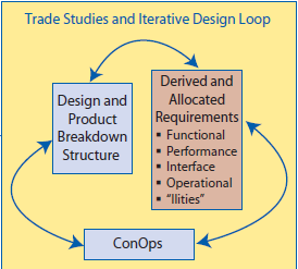
- Trade Studies and Iterative Design Loop
- Form Creative Design Solution (System PBS)
- Define Level 2 System and Subsystem Requirements
- Make Hardware and/or Software Model(s) and Perform Experiments
- Organize and Analyze Data
- Does Functional & Performance Analysis show design will meet Functional Design and concept of operations (ConOps) Requirements?
- If additional detail need, Repeat Process
- Select a preferred design
- Does the system work[3] (performance)?
- Is the system achievable within cost and schedule constraints?
- If the answer is no, adjust Customer’s Expectations (Step 1) and start again.
- Communicate Results (PDR and CDR)
- Preparing presentations (PDR and CDR)
- Reports, plans, and specifications. (Project Planning)
- Implement the design. (Project Implementation)
[/av_textblock]
[av_heading tag=’h3′ padding=’10’ heading=’The Design Process’ color=” style=” custom_font=” size=” subheading_active=” subheading_size=’15’ custom_class=” admin_preview_bg=” av-desktop-hide=” av-medium-hide=” av-small-hide=” av-mini-hide=” av-medium-font-size-title=” av-small-font-size-title=” av-mini-font-size-title=” av-medium-font-size=” av-small-font-size=” av-mini-font-size=”][/av_heading]
[av_textblock size=” font_color=” color=” av-medium-font-size=” av-small-font-size=” av-mini-font-size=” admin_preview_bg=”]
Design evolves through analysis and synthesis.
- Webster’s definition of design: to conceive and plan out in the mind; to build, create, fashion, execute, or construct according to a plan
- analysis: to divide a complex whole into its parts or elements; separating or distinguishing the component parts of something (as a substance, a process, a situation) so as to discover its true nature or inner relationship
- synthesis: the composition or combination of parts or elements so as to form a whole
[av_textblock size=” font_color=” color=” av-medium-font-size=” av-small-font-size=” av-mini-font-size=” admin_preview_bg=”]
- Design is an iterative process where the engineer must analyze the design (i.e., break apart, deconstruct), identify areas of greatest uncertainty, study (rapid prototype) possible solutions, and along the way eliminate poor or unsuitable solutions.
- Once the parts of a design are understood, the design can be synthesized (i.e., put back together, reconstructed) and the design studied as a whole (i.e., at the system level).
- Designs are evaluated based on the mission objectives and requirements.

[/av_textblock]
[av_heading tag=’h3′ padding=’10’ heading=’Design Process – Iteration I’ color=” style=” custom_font=” size=” subheading_active=” subheading_size=’15’ custom_class=” admin_preview_bg=” av-desktop-hide=” av-medium-hide=” av-small-hide=” av-mini-hide=” av-medium-font-size-title=” av-small-font-size-title=” av-mini-font-size-title=” av-medium-font-size=” av-small-font-size=” av-mini-font-size=”][/av_heading]
[av_image src=’https://www.arxterra.com/wp-content/uploads/2018/07/Design_process_5-1030×429.png’ attachment=’142129′ attachment_size=’large’ align=’center’ styling=” hover=” link=’lightbox’ target=” caption=” font_size=” appearance=” overlay_opacity=’0.4′ overlay_color=’#000000′ overlay_text_color=’#ffffff’ animation=’no-animation’ admin_preview_bg=”][/av_image]
[av_heading tag=’h3′ padding=’10’ heading=’Design Process – Iteration II’ color=” style=” custom_font=” size=” subheading_active=” subheading_size=’15’ custom_class=” admin_preview_bg=” av-desktop-hide=” av-medium-hide=” av-small-hide=” av-mini-hide=” av-medium-font-size-title=” av-small-font-size-title=” av-mini-font-size-title=” av-medium-font-size=” av-small-font-size=” av-mini-font-size=”][/av_heading]
[av_image src=’https://www.arxterra.com/wp-content/uploads/2018/07/Design_process_6-1030×446.png’ attachment=’142130′ attachment_size=’large’ align=’center’ styling=” hover=” link=’lightbox’ target=” caption=” font_size=” appearance=” overlay_opacity=’0.4′ overlay_color=’#000000′ overlay_text_color=’#ffffff’ animation=’no-animation’ admin_preview_bg=”][/av_image]
[av_heading tag=’h3′ padding=’10’ heading=’Design Process – Iteration III’ color=” style=” custom_font=” size=” subheading_active=” subheading_size=’15’ custom_class=” admin_preview_bg=” av-desktop-hide=” av-medium-hide=” av-small-hide=” av-mini-hide=” av-medium-font-size-title=” av-small-font-size-title=” av-mini-font-size-title=” av-medium-font-size=” av-small-font-size=” av-mini-font-size=”][/av_heading]
[av_image src=’https://www.arxterra.com/wp-content/uploads/2018/07/Design_process_7-1030×457.png’ attachment=’142131′ attachment_size=’large’ align=’center’ styling=” hover=” link=’lightbox’ target=” caption=” font_size=” appearance=” overlay_opacity=’0.4′ overlay_color=’#000000′ overlay_text_color=’#ffffff’ animation=’no-animation’ admin_preview_bg=”][/av_image]
[av_heading tag=’h3′ padding=’10’ heading=’Design Process – Techniques ‘ color=” style=” custom_font=” size=” subheading_active=” subheading_size=’15’ custom_class=” admin_preview_bg=” av-desktop-hide=” av-medium-hide=” av-small-hide=” av-mini-hide=” av-medium-font-size-title=” av-small-font-size-title=” av-mini-font-size-title=” av-medium-font-size=” av-small-font-size=” av-mini-font-size=”][/av_heading]
[av_textblock size=” font_color=” color=” av-medium-font-size=” av-small-font-size=” av-mini-font-size=” admin_preview_bg=”]
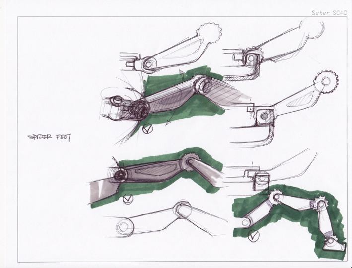
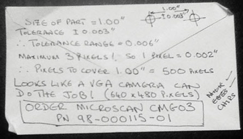
- There are many techniques an engineer might use to determine if an idea has promise.
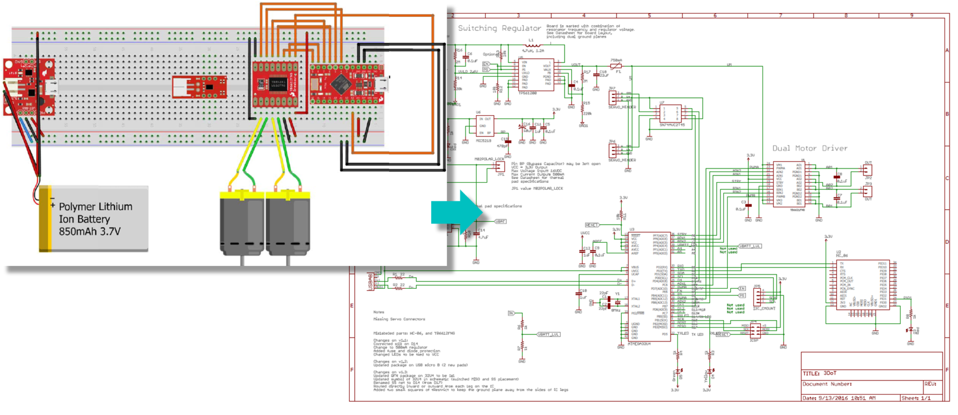
- Draw a preliminary sketch of the design
- Make a back of the envelope calculation
- Conduct a trade-off study
- Model the System
[av_heading tag=’h3′ padding=’10’ heading=’Design Process – Model the System’ color=” style=” custom_font=” size=” subheading_active=” subheading_size=’15’ custom_class=” admin_preview_bg=” av-desktop-hide=” av-medium-hide=” av-small-hide=” av-mini-hide=” av-medium-font-size-title=” av-small-font-size-title=” av-mini-font-size-title=” av-medium-font-size=” av-small-font-size=” av-mini-font-size=”][/av_heading]
[av_textblock size=” font_color=” color=” av-medium-font-size=” av-small-font-size=” av-mini-font-size=” admin_preview_bg=”]
- To facilitate the design process, engineers often rely on models.
- A model simplifies a system or process so that it may be better studied, understood, and used in a design.
- There are three common models used in engineering:
- Mathematical
- Computer Simulation
- Physical Models
- Full-scale Prototypes
- Scale Models
[/av_textblock]
[av_heading tag=’h4′ padding=’10’ heading=’Mathematical Models’ color=” style=” custom_font=” size=” subheading_active=” subheading_size=’15’ custom_class=” admin_preview_bg=” av-desktop-hide=” av-medium-hide=” av-small-hide=” av-mini-hide=” av-medium-font-size-title=” av-small-font-size-title=” av-mini-font-size-title=” av-medium-font-size=” av-small-font-size=” av-mini-font-size=”][/av_heading]
[av_textblock size=” font_color=” color=” av-medium-font-size=” av-small-font-size=” av-mini-font-size=” admin_preview_bg=”]
- Mathematical models usually consist of one or more equations that describe a physical system.
- Many physical systems can be described by mathematical models. Such models can be based on scientific theories or laws that have stood the test of time, or they may be based on empirical data from experiments or observations.
- In order to construct these mathematical models, simplifying assumptions are often made (e.g., the model system as an nth order constant coefficient linear differential equation).
- Mathematical models are usually employed for simple systems. The difficulty in deriving the equations for complex systems outweighs their usefulness.
[/av_textblock]
[av_three_fifth first min_height=” vertical_alignment=” space=” custom_margin=” margin=’0px’ padding=’0px’ border=” border_color=” radius=’0px’ background_color=” src=” background_position=’top left’ background_repeat=’no-repeat’ animation=” mobile_breaking=” mobile_display=”]
[av_image src=’https://www.arxterra.com/wp-content/uploads/2018/07/Design_process_10.png’ attachment=’142134′ attachment_size=’full’ align=’center’ styling=” hover=” link=” target=” caption=” font_size=” appearance=” overlay_opacity=’0.4′ overlay_color=’#000000′ overlay_text_color=’#ffffff’ animation=’no-animation’ admin_preview_bg=”][/av_image]
[/av_three_fifth]
[av_two_fifth min_height=” vertical_alignment=” space=” custom_margin=” margin=’0px’ padding=’0px’ border=” border_color=” radius=’0px’ background_color=” src=” background_position=’top left’ background_repeat=’no-repeat’ animation=” mobile_breaking=” mobile_display=”]
[av_image src=’https://www.arxterra.com/wp-content/uploads/2018/07/Design_process_11.png’ attachment=’142135′ attachment_size=’full’ align=’center’ styling=” hover=” link=” target=” caption=” font_size=” appearance=” overlay_opacity=’0.4′ overlay_color=’#000000′ overlay_text_color=’#ffffff’ animation=’no-animation’ admin_preview_bg=”][/av_image]
[/av_two_fifth]
[av_heading tag=’h4′ padding=’10’ heading=’Computer simulation models’ color=” style=” custom_font=” size=” subheading_active=” subheading_size=’15’ custom_class=” admin_preview_bg=” av-desktop-hide=” av-medium-hide=” av-small-hide=” av-mini-hide=” av-medium-font-size-title=” av-small-font-size-title=” av-mini-font-size-title=” av-medium-font-size=” av-small-font-size=” av-mini-font-size=”][/av_heading]
[av_textblock size=” font_color=” color=” av-medium-font-size=” av-small-font-size=” av-mini-font-size=” admin_preview_bg=”]
- Computer simulation models allow engineers to examine complex systems.
- These models typically incorporate many empirically1 based mathematical models as part of the total simulation model.
- From these empirically based models a computer program is written.
- This computer model is then subjected to many different simulated operating conditions.
- Simulation programs used in EE400D include Solidworks, LTSpice, MATLAB
[/av_textblock]
[av_image src=’https://www.arxterra.com/wp-content/uploads/2018/07/Design_process_12.png’ attachment=’142136′ attachment_size=’full’ align=’center’ styling=” hover=” link=” target=” caption=” font_size=” appearance=” overlay_opacity=’0.4′ overlay_color=’#000000′ overlay_text_color=’#ffffff’ animation=’no-animation’ admin_preview_bg=”][/av_image]
[av_heading tag=’h4′ padding=’10’ heading=’Physical models’ color=” style=” custom_font=” size=” subheading_active=” subheading_size=’15’ custom_class=” admin_preview_bg=” av-desktop-hide=” av-medium-hide=” av-small-hide=” av-mini-hide=” av-medium-font-size-title=” av-small-font-size-title=” av-mini-font-size-title=” av-medium-font-size=” av-small-font-size=” av-mini-font-size=”][/av_heading]
[av_textblock size=” font_color=” color=” av-medium-font-size=” av-small-font-size=” av-mini-font-size=” admin_preview_bg=”]
- Physical models have long been used by engineers to understand complex systems. They probably represent the oldest method of structural design.
- Physical models have the advantage in that they allow an engineer to study a device, structure, or system with little or no prior knowledge of its behavior or need to make simplifying assumptions.
- Full scale models are sometimes built, but most often they have been scaled down anywhere from 1:4 to 1:48.
- Examples of studies made with physical models include:
- Dispersion of pollutants throughout a lake.
- Behavior of waves within a harbor.
- Underwater performance of submarines of different shapes.
- Performance of aircraft by using wind tunnels to simulate various flight conditions
[/av_textblock]
[av_three_fifth first min_height=” vertical_alignment=” space=” custom_margin=” margin=’0px’ padding=’0px’ border=” border_color=” radius=’0px’ background_color=” src=” background_position=’top left’ background_repeat=’no-repeat’ animation=” mobile_breaking=” mobile_display=”]
[av_image src=’https://www.arxterra.com/wp-content/uploads/2018/07/Design_process_13.png’ attachment=’142137′ attachment_size=’full’ align=’center’ styling=” hover=” link=” target=” caption=” font_size=” appearance=” overlay_opacity=’0.4′ overlay_color=’#000000′ overlay_text_color=’#ffffff’ animation=’no-animation’ admin_preview_bg=”][/av_image]
[/av_three_fifth]
[av_two_fifth min_height=” vertical_alignment=” space=” custom_margin=” margin=’0px’ padding=’0px’ border=” border_color=” radius=’0px’ background_color=” src=” background_position=’top left’ background_repeat=’no-repeat’ animation=” mobile_breaking=” mobile_display=”]
[av_image src=’https://www.arxterra.com/wp-content/uploads/2018/07/Design_process_14.png’ attachment=’142138′ attachment_size=’full’ align=’center’ styling=” hover=” link=” target=” caption=” font_size=” appearance=” overlay_opacity=’0.4′ overlay_color=’#000000′ overlay_text_color=’#ffffff’ animation=’no-animation’ admin_preview_bg=”][/av_image]
[/av_two_fifth]
[av_heading tag=’h4′ padding=’10’ heading=’Prototypes and Scale Models’ color=” style=” custom_font=” size=” subheading_active=” subheading_size=’15’ custom_class=” admin_preview_bg=” av-desktop-hide=” av-medium-hide=” av-small-hide=” av-mini-hide=” av-medium-font-size-title=” av-small-font-size-title=” av-mini-font-size-title=” av-medium-font-size=” av-small-font-size=” av-mini-font-size=”][/av_heading]
[av_textblock size=” font_color=” color=” av-medium-font-size=” av-small-font-size=” av-mini-font-size=” admin_preview_bg=”]
- Many designers use full-scale prototypes to test the operation of the design.
- The prototype then helps the designer identify any weak areas of the design and hopefully how to improve upon them.
- No idea should be discarded solely on the basis of one prototype or one test. Many great designs have been discarded prematurely and many working prototypes have failed to give acceptable products.
[/av_textblock]
[av_image src=’https://www.arxterra.com/wp-content/uploads/2018/07/Design_process_15.png’ attachment=’142139′ attachment_size=’full’ align=’center’ styling=” hover=” link=’lightbox’ target=” caption=” font_size=” appearance=” overlay_opacity=’0.4′ overlay_color=’#000000′ overlay_text_color=’#ffffff’ animation=’no-animation’ admin_preview_bg=”][/av_image]
[av_textblock size=” font_color=” color=” av-medium-font-size=” av-small-font-size=” av-mini-font-size=” admin_preview_bg=”]
[/av_textblock]
[av_textblock size=” font_color=” color=” av-medium-font-size=” av-small-font-size=” av-mini-font-size=” admin_preview_bg=”]
Indirect evaluation can be used as well, to evaluate a design. Scale models can be used to test aircraft design at a fraction of the cost of building a prototype.
- Computer simulations and mathematical models may not be accurate enough to allow understanding of all the complexities of component interference or turbulence, but they still may be used to approximate the design of the first scale model for wind tunnel testing.
[/av_textblock]
[av_image src=’https://www.arxterra.com/wp-content/uploads/2018/07/Design_process_16.png’ attachment=’142140′ attachment_size=’full’ align=’center’ styling=” hover=” link=’lightbox’ target=” caption=” font_size=” appearance=” overlay_opacity=’0.4′ overlay_color=’#000000′ overlay_text_color=’#ffffff’ animation=’no-animation’ admin_preview_bg=”][/av_image]
[av_heading tag=’h3′ padding=’10’ heading=’Resources’ color=” style=” custom_font=” size=” subheading_active=” subheading_size=’15’ custom_class=” admin_preview_bg=” av-desktop-hide=” av-medium-hide=” av-small-hide=” av-mini-hide=” av-medium-font-size-title=” av-small-font-size-title=” av-mini-font-size-title=” av-medium-font-size=” av-small-font-size=” av-mini-font-size=”][/av_heading]
[av_textblock size=” font_color=” color=” av-medium-font-size=” av-small-font-size=” av-mini-font-size=” admin_preview_bg=”]
- Introduction to Engineering Design and Problem Solving
- Theories of Architectural Synthesis
- Jack Polymath
- robotic spider charecter design
- A Personal Guideline for Gauging with Machine Vision: My Three Pixel Rule
- Part 1: Choosing a Proper Dynamic System Model by Using Physical Modeling (System Identification Toolkit)
[/av_textblock]
[av_one_full first min_height=” vertical_alignment=’av-align-top’ space=” margin=’0px’ margin_sync=’true’ padding=’0px,0px,0px,20px’ border=” border_color=” radius=’0px’ radius_sync=’true’ background_color=” src=” attachment=” attachment_size=” background_position=’top left’ background_repeat=’no-repeat’ animation=” mobile_breaking=” mobile_display=”]
[av_button label=’View Exclusively’ link=’manually,https://www.arxterra.com/design-process-and-modeling/’ link_target=” size=’medium’ position=’left’ icon_select=’yes’ icon=’ue871′ font=’entypo-fontello’ color=’dark’ custom_bg=’#444444′ custom_font=’#ffffff’ admin_preview_bg=”]
[av_hr class=’custom’ height=’50’ shadow=’no-shadow’ position=’center’ custom_border=’av-border-fat’ custom_width=’1000px’ custom_border_color=’#ed9600′ custom_margin_top=’10px’ custom_margin_bottom=’0px’ icon_select=’no’ custom_icon_color=” icon=’ue808′ font=’entypo-fontello’ admin_preview_bg=”]
[/av_one_full]


