
By: Hector Martinez (Manufacturing)
Approved by: Ijya Karki (Project Manager)
Table of Contents
Intorduction
The prototype process should be thought out and well planned. There needs to be a plan that includes a parts list, a schematic, tools list and clean workspace. I had none of these. Having been moved from Prosthetic Arm there was a steep learning curve on walking robotics as well as understanding the state and direction of the Biped project as it stood. It was an uphill battle which included two redesigns 2 weeks before CDR. Having done two prototypes there are some things that I realize I could have done differently had I not been under the gun.
Process
Prototyping starts with SolidWorks (or whatever program you’re using) taking into consideration how your project will come together. You have to think about the hardware you are using and think about clearance and tolerances, as well as your materials. For example, while laser cutting the leg linkages for our first prototype for CDR, I didn’t realize the mounting holes for all the linkages were too close to the edges which resulted in broken mounts because these were cut from wood.

Fig. 1 – First prototype laser cuts, notice the mounting holes are really close to the edges
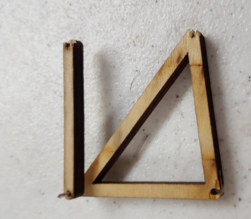
Fig. 2 – Broken linkages due to poor design
While putting together the second prototype for CDR, I decided to use acrylic and use M3 bolts to hold everything together. I didn’t consider the clearance of the bolt head and ended up having issues on several linkages hitting bolt heads due to insufficient clearance.
Another issue I ran into came from not researching the availability of part sizes, I assumed that I would be able to find M3 bolts up to 35mm. These were to be used on the feet to act as ankles and allow weight shifting. The feet were 3D printed and the mounting holes were set to 30mm, I decided to look for the hardware after printing and realized the longest M3 bolts I could get were 30mm.
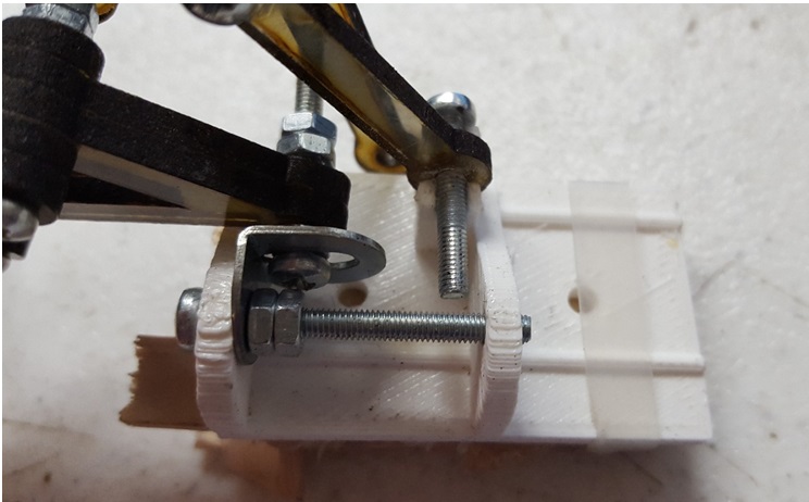
Fig. 3 – 30mm M3 screw used because 35mm screw was not available
Creativity
The thing about manufacturing is you have to learn to be creative. Some of the issues explained above had easy fixes, others didn’t, and for some the “fix” made things worse. For clearance issues I used spacers to create the clearance necessary. For the bolts that weren’t long enough I bolted them in such a way that they were still secured. Except for one of these bolts I decided to use superglue which fixed the bolt to the foot (Fig. 3), these were meant to fit loosely to allow for rotation. In this case you need to realize what you did wrong and fine the best solution. In my case the only option was to 3D print that foot again.
Fig. 4 – Spacers and nuts used to lock linkages in place, locking nuts would have been a better alternative
Conclusion
The purpose of prototyping is to discover issues with your design as well as what is missing. For our prototype we wanted to know if our design would statically walk. While testing we discovered that our robot could not stand because the angle of the linkages would not allow it stand. Brandon, our E&C, suggested we make “shoes” to correct this issue. By making shoes we were able to move forward and continue testing our walking motion. While this was a quick fix for CDR, prototyping pointed to a major design flaw that needs to be addressed.
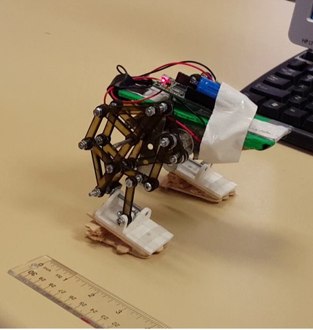
Fig. 5 – Prototype with “shoes” to correct stance, and tape to hold the 3dot board
Resources
[1] Solidworks