Fall 2016 Biped – Updated Schematics
By: Alan Valles (Electronics and Control)
Approved by: Ijya Karki (Project Manager)
Table of Contents
Introduction:
The purpose of this document is to define and go through some of the choices and reasons for component selection of the custom 3dot shield. There are a couple main components that were chosen for the shield, the IMU which is the MPU-6050 which is provided by The Robot Company. The SX1509B which is the GPIO expander, ADS1015 the Analog to Digital converter for the rotary position sensor.
Analysis:
First, the IMU chosen was the MPU-6050. The original MPU breakout board was designed by sparkfun and has a retail price of 39.95. However, an imitation board with similar functionality was provided by The Robot Company. Since this was provided at no additional cost to the project, it was selected based on price. A 10-pin .1” pitch socket was provided on the 3dot Shield for the MPU-6050 Breakout Board to connect to. This board also plays nice with the 3dot board since it has a 3.3 v logic level.
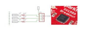
The SX1509B is a low power GPIO expander that was selected for the 3dot board. Since latest revision of the 3dot board does not have any available I/O ports it was decided to use an I2C GPIO expander since the SX1509 has PWM capabilities it may be able to control the signal of a servo. This is needed in order to shift weight between feet in order to produce a walking motion with the robot. The SX1509 also has a sparkfun library which aids in meeting scheduling deadlines of the project. Another small peripheral device was the color pad indicator light. It will connect to an LED on the top of the Robot and when a power pad is walked over, the light will turn on per the game rules. Some SMD resistors were added to the PCB so the final assembly will just house the LED itself. The optimal brightness is around 560 Ohms for the through hole RGB LED that will be used. This bright ness is based on the forward voltage required by the different colored LEDs. Thus, since diodes emitting at different colors, or wavelengths will generally require different current limiting resistors to dictate the brightness. The LEDs need a forward current of about ~160 more or less and thus something close to this value will be used.
Furthermore, the ADS1015 was selected as the Analog to Digital converter which would be able to read information from our rotary positions sensor. The ADS1015 was selected due to the available documentation, spark fun library, and due to the recommendation of the velociraptor group. This collaborative effort will help drive projects forward by allowing for more code between them. Also, Adafruit provides a library for utilizing this component as well and has some good documentation on their website utilizing this device. The Rotary position sensor used will be of the BOURNS 3382 series. The bourns rotary positions sensor is a potentiometer that can support 360 degree continuous rotation, ideal for the output shaft of the dc motor. The diameter of our shaft is a 3mm hexagonal pattern and should fit into the bourns 4mm rotary position sensor based on the datasheet.
Finally, at the recommendation of our President, I made the decision to connect our entire system to a Linear Dropout regulator which will provide 5V to the servos instead of having them tap directly to the output voltage of the battery. The LM1084IS by Texas Instruments was chosen as the voltage regulator. This was because it provides 5V and up to 5A output. Also due to the availability of a convenient eagle part. The TI LM1084 was configured in a typical application circuit as shown below. A Solder jumper was placed for added flexibility. This solder jumper allows for a different battery voltage to still be applied such as a 3.7v battery and the servo would connect to this unregulated.
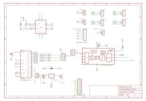
This is our final completed schematic for the 3dot shield. It shows all the components that were listed above. The finalized board layout can also be seen in our Manufacturing Engineers blog post who did a wonderful job. Along with the major components there are also some pullup resistors for the I2C bus which are sized due the length of cable connecting all devices, however 4.7k or 10k are good ‘default’ values if one does not want to go through the process of calculating mutual inductances and capacitances. It is also good practices to put decoupling caps in front of voltage inputs of sensitive components. This will block any noisy High frequency signals from affecting the chip’s performance. There is a handy guide on how to size and select decoupling capacitor values based on Farads, Equivalent Series Resistance in reference [9] but be warned it is not a read for the faint of heart. A github link will be included at a later time, including all of the schematics, and necessary libraries to modify and rebuild this project.
Conclusion:
In conclusion, The 3dot shield was made using the MPU6050 breakoutboard, the ADS1015, LM1084, and other miscellaneaous passive components. The LM1084 provides regulated 5v to the 3dot board and all of the other peripheral devices tap to the 3.3v power and logic level of the 3dot board.
Reference:
[1] https://www.sparkfun.com/products/11028
[2] https://www.geeetech.com/triple-axis-accelerometergyro-breakout-mpu6050-p-539.html
[3] http://www.mouser.com/ds/2/761/down-767043.pdf
[4] http://www.ti.com/lit/ds/symlink/ads1015.pdf
[5] http://www.ti.com/lit/ds/symlink/lm1084.pdf
[6] https://www.sparkfun.com/products/13601
[7] https://www.sparkfun.com/datasheets/Components/YSL-R596CR3G4B5C-C10.pdf
[8] http://www.bourns.com/pdfs/3382.pdf
[9] http://www.analog.com/media/en/training-seminars/tutorials/MT-101.pdf
Resource
[1] Eagle Design


