[av_hr class=’default’ height=’50’ shadow=’no-shadow’ position=’center’ custom_border=’av-border-thin’ custom_width=’50px’ custom_border_color=” custom_margin_top=’30px’ custom_margin_bottom=’30px’ icon_select=’yes’ custom_icon_color=” icon=’ue808′ font=’entypo-fontello’]
[av_image src=’/wp-content/uploads/2016/11/Fig7.jpg’ attachment=’20214′ attachment_size=’full’ align=’center’ styling=” hover=” link=” target=” caption=” font_size=” appearance=” overlay_opacity=’0.4′ overlay_color=’#000000′ overlay_text_color=’#ffffff’ animation=’no-animation’][/av_image]
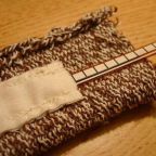
[av_heading heading=’Fall 2016 Prosthetic Hand: PDR Rapid Prototype’ tag=’h2′ style=’blockquote modern-quote modern-centered’ size=” subheading_active=” subheading_size=’15’ padding=’10’ color=” custom_font=”][/av_heading]
[av_textblock size=” font_color=” color=”]
Electronics and Control Engineer – Younis Al-Kharusi
[/av_textblock]
[av_one_full first min_height=” vertical_alignment=” space=” custom_margin=” margin=’0px’ padding=’0px’ border=” border_color=” radius=’0px’ background_color=” src=” background_position=’top left’ background_repeat=’no-repeat’ animation=”]
[av_textblock size=” font_color=” color=”]
In PDR, our goal was to experiment with different methods of control and actuators including flex sensors versus pushbuttons and servos versus DC motors, respectively. Also, when selecting actuators, it was important to test different DC motors that produced various speeds, comparing and contrasting their performance, seeing which one would be most plausible for our control system design. We had three moving prosthetic fingers with different types of actuators: a servo, a 6V 60 RPM DC motor, and a 12V 10 RPM DC motor. The aforementioned actuators were then controlled via a flex sensor attached to a user’s foot. As the foot was bent, flexing the sensor, the actuators would then produce a response. Each control method and actuator response is detailed below.
[/av_textblock]
[/av_one_full][av_hr class=’default’ height=’50’ shadow=’no-shadow’ position=’center’ custom_border=’av-border-thin’ custom_width=’50px’ custom_border_color=” custom_margin_top=’30px’ custom_margin_bottom=’30px’ icon_select=’yes’ custom_icon_color=” icon=’ue808′]
[av_one_third first min_height=” vertical_alignment=” space=” custom_margin=” margin=’0px’ padding=’0px’ border=” border_color=” radius=’0px’ background_color=” src=” background_position=’top left’ background_repeat=’no-repeat’ animation=”]
[av_heading heading=’Finger 1′ tag=’h3′ style=’blockquote classic-quote’ size=” subheading_active=” subheading_size=’15’ padding=’10’ color=” custom_font=”][/av_heading]
[/av_one_third][av_two_third min_height=” vertical_alignment=” space=” custom_margin=” margin=’0px’ padding=’0px’ border=” border_color=” radius=’0px’ background_color=” src=” background_position=’top left’ background_repeat=’no-repeat’ animation=”]
[av_textblock size=” font_color=” color=”]
The flex sensor values produced when bending the sensor ranged between 20-200. These values correlated to the voltage in the sensor produced when it was bent, 20 meaning slightly bent and 200 meaning fully bent. Theses values were then transmitted wirelessly from an Arduino Leonardo via an XBEE module to a receiving XBEE module and Arduino Uno. Once the values produced by the flex sensor were received by the Arduino UNO, they were mapped to control the rotation of the servo’s shaft, varying from 0 to 180 degrees. When the sensor was flexed on the foot, the servo reacted almost instantaneously, mimicking that same flexed motion. However, when trying to control the finger using flex sensors, we noticed that it was difficult to control a single prosthetic finger using the foot. The design of the prosthetic hand would need to independently control five fingers. So far, flex sensors were not appearing to be a viable control method.
[/av_textblock]
[/av_two_third][av_hr class=’default’ height=’50’ shadow=’no-shadow’ position=’center’ custom_border=’av-border-thin’ custom_width=’50px’ custom_border_color=” custom_margin_top=’30px’ custom_margin_bottom=’30px’ icon_select=’yes’ custom_icon_color=” icon=’ue808′]
[av_one_third first min_height=” vertical_alignment=” space=” custom_margin=” margin=’0px’ padding=’0px’ border=” border_color=” radius=’0px’ background_color=” src=” background_position=’top left’ background_repeat=’no-repeat’ animation=”]
[av_heading heading=’Finger 2′ tag=’h3′ style=’blockquote classic-quote’ size=” subheading_active=” subheading_size=’15’ padding=’10’ color=” custom_font=”][/av_heading]
[/av_one_third][av_two_third min_height=” vertical_alignment=” space=” custom_margin=” margin=’0px’ padding=’0px’ border=” border_color=” radius=’0px’ background_color=” src=” background_position=’top left’ background_repeat=’no-repeat’ animation=”]
[av_textblock size=” font_color=” color=”]
As mentioned in the previous section, Finger 1, the data transmission procedure was the same. The flex sensor values were sent from the Arduino Leonardo through an XBEE module to a second XBEE module and Arduino UNO. The code uploaded to the Arduino UNO was written to detect a flexing foot gesture by storing the previous values produced by the sensor and comparing it with present values to detect any sharp changes. When an initial pinch gesture is detected, the prosthetic finger flexes in the closed position, and when the next pinch gesture is detected, the finger retracts back into an open position. The DC motor is timed so that is it moves for 1 second, and stops when during flexion and retraction. The problem with timing the motor, is that after so many flexion motions, the finger would gradually drift from its intended flexing location, and have to be recalibrated.
[/av_textblock]
[/av_two_third][av_textblock size=” font_color=” color=”]
The video below shows both fingers 1 and 2 being controlled. Also listed is the code used to control fingers 1 and 2.
Video Link: https://1drv.ms/v/s!AtATn2tNizopeA3_AO08uZmK5-o
Code Link: https://drive.google.com/open?id=0BzJlMPCB0tFPNG94YUN2TTVjckk
[/av_textblock]
[av_hr class=’default’ height=’50’ shadow=’no-shadow’ position=’center’ custom_border=’av-border-thin’ custom_width=’50px’ custom_border_color=” custom_margin_top=’30px’ custom_margin_bottom=’30px’ icon_select=’yes’ custom_icon_color=” icon=’ue808′]
[av_one_third first min_height=” vertical_alignment=” space=” custom_margin=” margin=’0px’ padding=’0px’ border=” border_color=” radius=’0px’ background_color=” src=” background_position=’top left’ background_repeat=’no-repeat’ animation=”]
[av_heading heading=’Finger 3′ tag=’h3′ style=’blockquote classic-quote’ size=” subheading_active=” subheading_size=’15’ padding=’10’ color=” custom_font=”][/av_heading]
[/av_one_third][av_two_third min_height=” vertical_alignment=” space=” custom_margin=” margin=’0px’ padding=’0px’ border=” border_color=” radius=’0px’ background_color=” src=” background_position=’top left’ background_repeat=’no-repeat’ animation=”]
[av_textblock size=” font_color=” color=”]
The method for controlling Finger 3 was changed from a flex sensor to two pushbuttons. This control system was constructed to use two pushbuttons: one to flex the prosthetic finger and the other to retract it. When the first button was pressed, the DC motor flexed in response. However, when the second pushbutton was pressed, the finger would retract.
[/av_textblock]
[/av_two_third][av_hr class=’default’ height=’50’ shadow=’no-shadow’ position=’center’ custom_border=’av-border-thin’ custom_width=’50px’ custom_border_color=” custom_margin_top=’30px’ custom_margin_bottom=’30px’ icon_select=’yes’ custom_icon_color=” icon=’ue808′]
[av_video src=’https://youtu.be/SrvMPg8z38E’ format=’16-9′ width=’16’ height=’9′]
[av_textblock size=” font_color=” color=”]
Video – PDR Demo Video
[/av_textblock]
[av_hr class=’default’ height=’50’ shadow=’no-shadow’ position=’center’ custom_border=’av-border-thin’ custom_width=’50px’ custom_border_color=” custom_margin_top=’30px’ custom_margin_bottom=’30px’ icon_select=’yes’ custom_icon_color=” icon=’ue808′]
[av_one_full first min_height=” vertical_alignment=” space=” custom_margin=” margin=’0px’ padding=’0px’ border=” border_color=” radius=’0px’ background_color=” src=” background_position=’top left’ background_repeat=’no-repeat’ animation=”]
[av_heading heading=’Conclusion’ tag=’h3′ style=’blockquote classic-quote’ size=” subheading_active=” subheading_size=’15’ padding=’10’ color=” custom_font=”][/av_heading]
[/av_one_full][av_one_full first min_height=” vertical_alignment=” space=” custom_margin=” margin=’0px’ padding=’0px’ border=” border_color=” radius=’0px’ background_color=” src=” background_position=’top left’ background_repeat=’no-repeat’ animation=”]
[av_textblock size=” font_color=” color=”]
In conclusion, the servo produces proportional control. However, it does not fit the mechanical design. The servo would not provide the torque required to lift a drink, and controlling five independent fingers using a foot or toes. Using flex sensors would be inconvenient. Furthermore, controlling the prosthetic fingers with a flexing gesture would require timed DC motors. Timing DC motors are not always accurate or reliable in terms of producing consistent responses. Finally, after much comparing and contrasting, pushbuttons were concluded to be the ideal solution for controlling the actuators because the motors only move when a button is pressed and stop once it is released which is the desired motion of the prosthetic fingers.
[/av_textblock]
[/av_one_full]