Project Manager – Paul Ahumada
Electronics and Control Engineer – Kevin Armentrout
Manufacturer and Design Engineer – Victoria Osaji
Systems Engineer – Robert Licari
Table of Contents
Program Objectives/Mission Profile
By Paul Ahumada
3rd Generation Velociraptor is a robot developed by the CSULB 2016 Fall Semester class that will expand on previous semester’s designs. The Velociraptor is to be a toy resembling Theropoda dinosaurs. Velociraptor shall compete in a Jurassic/Modern Game: Save The Human with other toys on the last day of class, December 15, 2016. The game will involve Velociraptor chasing another robot through various terrain by tele-robotic communication on the Arxterra Control Panel. The arena the Velociraptor must traverse is developed by the Game Committee and customer. The mission will display the robotic applications of the 3DoT Board developed by Arxterra and Velociraptor’s movement capabilities. – PM Paul Ahumada
Requirements and Verification
Program/Project
By Paul Ahumada
Level 1 Program Requirements
The Level 1 Program Requirements may resemble this:
- The 3rd Generation Velociraptor shall participate in the Game: Save The Human proposed by the game committee
- 3rd Generation Velociraptor budget shall not cost more than $450.00. This estimate was based upon 2nd and 1st Generation Bipeds [7] [15]
- The Velociraptor shall demonstrate its capabilities on this December 15, 2016 according to CSULB Calendar 2016-2017 [14]
Level 1 Project Requirements
The Level 1 Project Requirements may resemble this
Level 1 Requirements
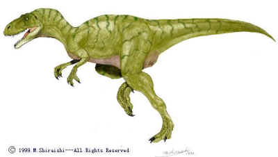
- The Velociraptor shall resemble a T-Rex of the Theropoda Dinosaur class [13]
- The Velociraptor shall navigate through the game terrain provided by the game committee. Velociraptor shall:
- Navigate on incline/declines no greater than 6.5 degrees
- Shall navigate on uneven surface heights no larger than .5 cm
- Shall utilize a foot design capable of traction on all surfaces
- Battery shall provide sufficient power to robot for duration of the game
- The Velociraptor shall statically walk [16]
- The Velociraptor shall dynamically walk [16]
- The Velociraptor shall use Bluetooth to communicate with Arxterra Control Panel [17]
- The Velociraptor shall use a 3DoT board and implement I2C [17]
- The Velociraptor shall use a Portable Power Source
System/Subsystem
Level 2 System Requirements
By Paul Ahumada
- Shall implement a control system [PID or State Space] which shifts CoG on axis of legs maintain stability. The CoG shall be changed by two servos. There is one servo to control the head and one servo to control the tail. The acceleration and velocity of the CoG of the head and tail shall not exceed [data to be calculated] in order to avoid having momentum tip over the robot. [Level 1-1]
- Shall implement control system [PID or State Space] which shifts CoG on axis of head, body and tail to maintain stability. The CoG shall be shifted by a servo controlling the platform of the body. The acceleration and velocity of the CoG of the body shall not exceed [data to be calculated] in order to avoid momentum causing robot to fall down. [Level 1-1]
- Shall have two legs supporting mass of robot. [Level 1-1]
- Shall use leg design that operates with cyclical movement that shall be controlled by a DC motor. [Level 1-1]
- Shall implement a control system which shifts the CoG over the planted leg while statically walking. The shifted CoG mass shall be within [to be calculated value] mm center of foot. The distance shall not consider vertical distance, Z. The distance from CoG and center of foot shall be calculated by margin of stability [to be calculated]. [Level 1-3]
- Shall implement a control system which tracks X, Y, and Z angles to the [to be found] precision. [Level 1-4]
- Shall implement a control system which tracks acceleration in the X, Y, and Z planes to the [to be found] precision. [Level 1-4]
- Shall track head and tail position to shift CoG by collecting data of servo angles to the [to be found] precision [Level 1-4]
- Shall utilize Bluetooth LE interface to provide Velociraptor commands from Arxterra Control Panel [Level 1-5]
- Shall connect head and tail servos via 3DoT Board servo interface. [Level 1-6]
- Shall implement an IMU [to be determined what kind] that communicates via I2C at a frequency rate [to be found] Hz. IMU data that collected shall be implemented into control systems. [Level 1-6]
- Shall use a CR123A 650mA rechargeable Li-ion battery from 3DoT Board [Level 1-6]
- Shall implement a motor controller [to be determined what kind] on the motor shield that communicates via I2C at a frequency rate [to be found] Hz. [Level 1-6]
- May use rechargeable batteries to power the Robot. [Level 1-7]
- The robot shall be able to continuously operate in game arena for minimum one hour. [Level 1-2]
- IMU shall send data as inputs to control systems for dynamic stability when encountering uneven surfaces and incline/declines [Level 1-2.1]
- Model of foot [to be decided] design shall [calculated] surface area to provide stability and not impede movements
- Traction of foot [to be determined] shall provide enough friction on all surfaces [study to be shown] of game terrain to prevent raptor falling over. [Level 1-2]
- Shall change direction, left or right, by [to be determined arc] while walking. [Level 1-1]
- Shall be able to change direction for range 0-360 degrees, left or right, while not walking. [Level 1-1]
- Arduino Microcontroller Leonardo shall implement control algorithms [to be made] to be used in stability and user control of robot. [Level 1-7]
Level 2 Subsystem Requirements
Electronics Subsystem Requirements
By Kevin Armentrout
- Shall use batteries with a series terminal voltage of 3.7V. [Level 2-12] [4]
- Shall use leg motors with a gear ratio to produce a stall torque rating of at least 223 mN-m [Level 2-3] [Appendix]
- Shall use a leg design with a primary lever arm length of at a maximum of 7cm [Level 2-3] [Appendix]
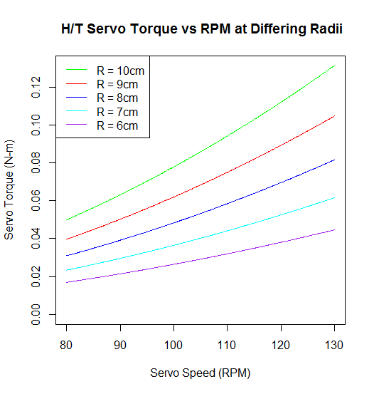
- Shall use head and tail servos which produce a minimum of 50 mN-m of torque at 80 RPM and 125 mN-m of torque at 130 RPM. [Level 2-1] [Head and Tail Torque Graphs]
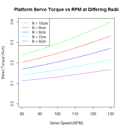
- Shall use a platform positioning servo that operates with a max speed of 80 RPM and a minimum torque rating of 238 mN-m. [Level 2-18] [Platform Graphs]
- Shall use a turning servo with a minimum torque rating of 139 mN-m. [Level 2-19] [Appendix]
Design Innovation
From our Creativity Presentation, we were able to generate ideas on how to talk challenges the 3rd Generation Velociraptor encounters. Major problems we must tackle for Fall 2016 is the ability to turn, CoG shifting along axis of head and tail, and changing the legs to cyclical movements. We have come across different solutions for each of these. For turning, we are thinking of using a servo to help the legs orientate a change in direction. Stabilizing an inverted pendulum will be the basis of our stabilization for the axis along the head and tail. Finally, the legs we are considering using are the UCI linkages because of their unique step pattern compared to Theo Jensen.
Systems/Subsystem Design
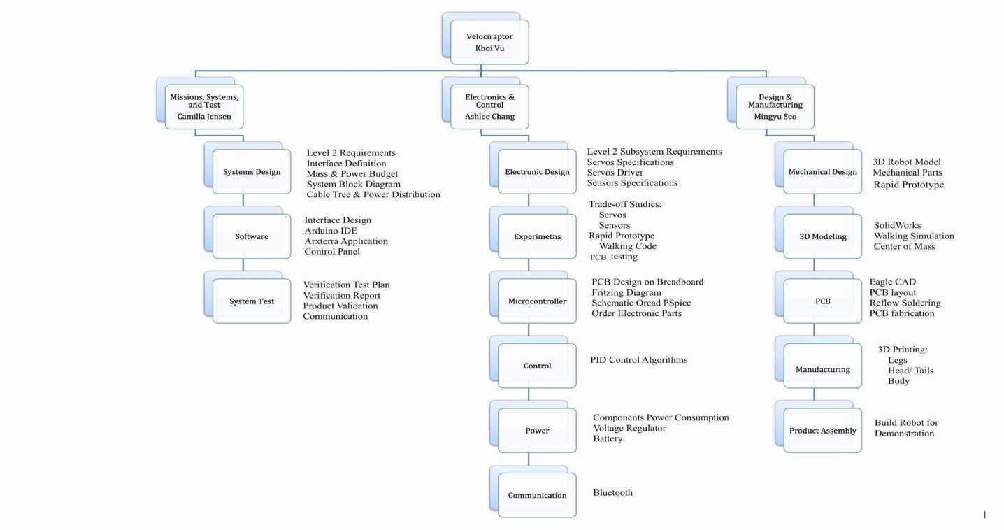
Product Breakdown Structure
TBA
Electronic System Design
System Block Diagram
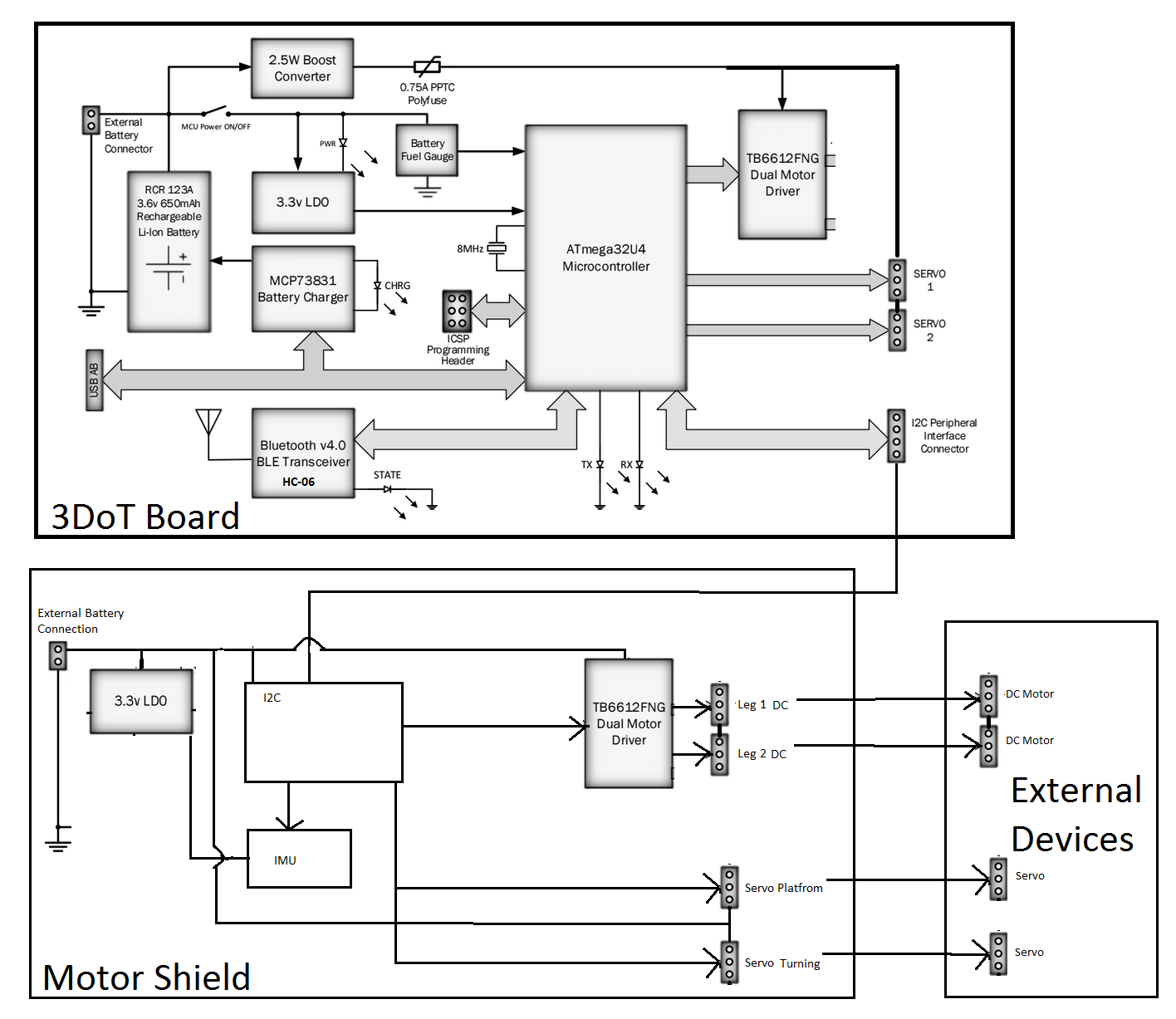
The electronic interface provides an idea of how the customer provided 3DoT board will move our robot. We used the 3DoT Block Diagram to get started. We will need a motor shield to connect to external devices that cannot fit onto the 3DoT board. Luckily, there is an I2C interface from the 3DoT board that allows us to add more devices. Because we need an I2C interface, we need an I2C chip that can connect to the amount of devices we needed. The I2C chip is explained in the Electronics research under design descriptions. The reason we do not have our DC motors directly connected to the 3DoT board is because it will always blow the polyfuse as determined by the mass of the robot. Further research will go into whether the 3DoT Dual Motor drive is the best fit in our motor shield. The electronics research goes into detail of the torque required to move our mass and the rpm needed.
Interface Definitions
TBA
Mechanical Design
TBA
Design and Unique Task Descriptions
Project Manager Research
As part of the game arena, friction coefficients of the surfaces must be found so our robot can maintain traction throughout the game. The table provided below shows that rubber has a higher static coefficient on cardboard than linoleum. This information helps if we would like to have rubber soles on our robot. Information that would be valuable that could not be found would be using plastic and also a study for friction coefficients on carpet. This information can be found from experimentation of by having a pulley design with one end having a mass dangling in the air and another end having our plastic or rubber mass. As we add more weight to the dangling mass, eventually the plastic or rubber mass on a surface will move.
| Case Study Friction Coefficients | Static Frictional Coefficient | |
| Rubber on Cardboard | .5-.8 | Source Cardboard |
| Rubber on Linoleum | .3-.5 | Source Linoleum |
Electronics Research
By Kevin Armentrout
Leg Motors
Level II System requirements dictated that motors would be used as the locomotive method for the Raptor robot. This is challenging for a number of reasons. First, motor position cannot be accurately controlled to specify angles of motion. Even if motor shaft position was monitored by means of a rotary encoder or other shaft measurement device, starting position would be a challenge. Secondly, motors tend to occupy a larger space and weigh more than servos. [1]
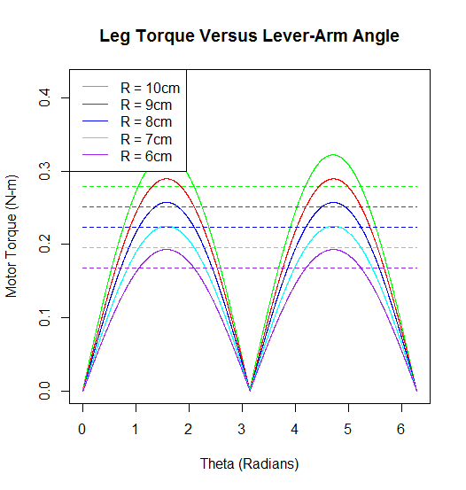
Analysis was performed in R to measure the maximum and operational torque values of various lever-arms, using the weight from the previous semester’s raptor as a basis for analysis. Full analysis code is in the appendix below. This analysis was performed using lever arms from 6 to 10 cm and calculating the maximum operational torque due to gravity and centripetal force. 10cm was approximately the length of the raptor’s head, leg and tail from last semester. Our design would be a modification from the previous semester so it was important to consider other level arm distances that were not used from last semester. This importance was especially emphasized by the fact that the legs will need to be completely redesigned to allow for continuous motion. This brought upon the condition that the primary lever arm of the motors and servos may need to change to conform to motor torque requirements, thus the range from 6 to allow for further lever arm considerations.
Once maximum torque values were calculated, torque over the leg motion cycle was calculated by applying a sin to the position. Cursory analysis of the primary lever arm, which would be exerting the highest magnitude of torque on the motor, showed that the lever arm typically rotated between 210 and 330 degrees [2]. This corresponded to a value, which I identify as a realistic maximum, or sin(60) of the calculated maximum. Logical analysis of leg locomotion confirms this. Using the Y-Axis of your leg as a reference, it typically will not exceed 60 degrees on a single stepping motion. The realistic torque values for the legs at various lever-arm lengths is listed in the appendix below.
Head and Tail Servos
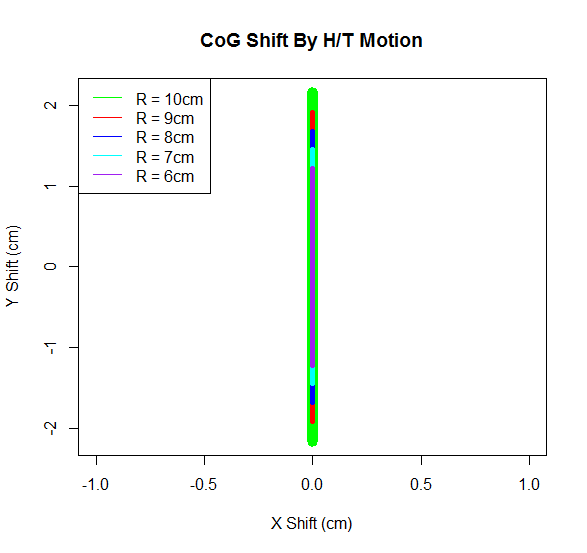
The level II requirement that dictated the need to move the head and the tail stemmed from the need to shift the CoG to the planted foot, or maintain in stationary during dynamic movement. To evaluate how the CoG will shift, an analysis on moments of inertia needed to be performed over the full motion of the tail. Disassembly of the previous semester’s raptor to weigh the individual segments was impractical, so an analysis of material density, and weight of the components used on the head and tail segments was done in its place.
Density of ABS plastic, as well as length and width of the tail was taken into account, as well as the dimensions of the battery holder. The batteries used were AAs, and dimensions and weight of the AA batteries were taken into tail and head mass calculations. The torque was based on centripetal speed of the servos. Analysis of 5V servos showed that the majority of servos were in the 80-130 RPM range, which was used for our analysis of torque due to centripetal force.
An additional factor for consideration, similar to the legs, was varying the head and tail radius, and its effect on the CoG and centripetal torque. Servos must be selected with torque rating that is greater than the curve shown below for the specified radius length.
![[7]](https://www.arxterra.com/wp-content/uploads/2016/04/Final-cost-report-copy-2.jpg)
Platform Servo
The platform servos will be used to move the entire control surface of the body in order to account for changes on the X-Z plane. In order to facilitate movement of the surface along this plane, we will need to account for the mass of the head and tail, as the Body components near the CoM will produce negligible torque due to the lever arm being of a small radius. This simplified the torque calculations to only concern the centripetal force of the motion along the Y axis, and the torque related to gravity. Below is the calculated chart with different servo speeds and head/tail radii. The selection of the Platform servo must exceed these values.
Turning Servo
Unlike the other electric components, the turning servo must be able to turn the entire platform left and right to control the robot’s direction. This requires the torque that is applied to the servo to not only be the entire mass of the robot, but also the additional force due to the frictional coefficients of the surfaces of the robot will walk on. The calculated number is the torque on the servo solely due to the mass of the robot. This number, still, is quite substantial, and other solutions may be needed to be explored to allow the robot the ability to turn in a precise manner.
Batteries
Batteries are to be considered for the following purposes. Primarily, their current capacity, as it will provide the necessary resource to power the robot’s electronics and actuators, and secondly, it’s form factor and weight as a method of balance for the robot. Last semester, and the semester previous did a clever design with the batteries, placing them as counter weights on the head and tail. This evenly distributed the CoG along the X and Y axis, and also allowed the CoG to shift as the tail moved. For this purpose, the AA form factor for batteries was considered as counter weights and primary power, and the slim form factor is considered as platform supplementary power.
Current draw was calculated by use of manufacturer ratings for representative components that fit the requirements for the motors and sensors, as well as the components of the 3DoT board. However, servo current load is not a required manufacturer listed quantity, and as such, is simply not listed on any of the servos we examined. Additionally, all servos listed on Sparkfun, Adafruit, Digikey, and Mouser have a minimum 5V rating. This would change the current-hours equivalent to a Watt-hour equivalent for consistency, as all other components will be powered via the 3.3V bus. For these points the servo calculations will be ignored for this initial power consumption analysis as they are not representative of actual values, and would be a best guess approximation.
The calculations took into account average motor load and peak sensor load to determine the following. Once again, these numbers are representative, and are not the actual final values that will be used for a full power analysis.
I2C
I2C functions in a daisy chain manner similar to USB, but has an address structure that is different. I2C can support up to 127 different addresses, but these addresses are unique and programmed at the hardware level [3]. Thus it is important that these addresses do not overlap in order to have proper sensor and control function. The 3DoT board is equipped with 2 Motor headers, 2 servo headers, and an I2C header, leaving at minimum 2 Servos that would need I2C control, and the IMU which would need I2C communication [4].
Motor Controller
A derived requirement from the number of servos and motors need for Robot operation is the need for an external motor controller shield. If the motors are to be placed on the shield, bi-directional motion would be necessary. This can be accomplished by means of an H-Bridge [5]. For the servos that would be attached, a PWM I2C controller would need to be utilized to ensure proper control over the devices. An ideal solution for rapid prototyping is a board that has both PWM functionality and H-Bridges for motor and servo control.
Inertial Mass Unit (IMU)
The need for an IMU comes from the requirement for dynamic stability of the Robot. In order to maintain the Robot dynamically stable, an accurate accountancy of both angular position on a three dimensional axis, and inertial shift detection by means of an accelerometer [6]. Due to the 3DoT board not having external pin headers except for those listed in the I2C descriptions, the interface for communicating with the IMU must be I2C.
Appendix
| Peak Torques (N-m) | ||||||
| Radius | 10 cm | 9 cm | 8 cm | 7 cm | 6 cm | |
| Component | Platform | 0.238 | 0.203 | 0.170 | 0.140 | 0.113 |
| Legs | 0.279 | 0.251 | 0.223 | 0.192 | 0.167 | |
| Head/Tail | 0.050 | 0.040 | 0.031 | 0.023 | 0.017 | |
| Turning | 0.139 | 0.123 | 0.108 | 0.093 | 0.079 | |
| Representative Components Which Met Torque Criteria | |||||||
| Servo/ Motor | Torque
(N-M) |
Weight
(g) |
Cost
($) |
NL Current
(A) |
FL Current
(A) |
RPM | Notes |
| Motors | |||||||
| ROB-12399 | 0.322 | 119 | 24.95 | 0.095 | 0.5 | 101 | (@12V) [A6] |
| Tamiya 72005 | 0.235 | 140 | 13.95 | 0.15 | 2.7 | 51.3 | [A7] |
| Tamiya 70168 – Double | 0.223 | 120 | 9.25 | 0.15 | 2.1 | 38 | [A1] |
| Servos | |||||||
| FS5103R | 0.294 | 40 | 11.95 | NL | NL | 80 | (@5v) [A8] |
| EMAX ES08A | 0.148 | 8.5 | 9.9 | NL | NL | 83.3 | (@5v) [A9] |
| Seeed 108090001 | 0.197 | 12.25 | 21.9 | NL | NL | 83.3 | (@5v) [A10] |
| Seeed 108090002 | 0.245 | 19.96 | 24.9 | NL | NL | 100 | (@5v) [A11] |
| Component | Average Current | Source |
| Leg Motors | 1.583 A | [A1] |
| Leonardo (3DoT) | 0.56 A | [A2-A3] |
| IMU | 0.00686 A | [A4] |
| Motor Shield | 0.01 A | [A5] |
| Total | 2.16 A |
R Source Code for Calculations
| # Determined by the Servo
stepSize = (pi/180)*(360/3000) thetaHead = seq(-pi/2,pi/2,stepSize) thetaTail = -thetaHead thetaLeg = seq(0,2*pi,stepSize) # In RPM MaxSpeed = seq(80,130,.1)
# Max Incline on Y Axis
MaxY = (6.5*pi/180)
# Centripital Acceleration # http://www.engineeringtoolbox.com/centripetal-acceleration-d_1285.html
A = (2*pi*MaxSpeed/60)^2 * Radius/100
# AA weight is 23g # AA dimensions are in cm, which is used to determine ABS plastic # Battery holder mass # http://data.energizer.com/PDFs/E91.pdf
innerLength = 5.050 innerWidth = 1.450 *2 innerHeight = 1.450
outerLength = innerLength + .5 outerWidth = innerWidth + .5 outerHeight = innerHeight + .5
HolderVolume = (outerLength * outerWidth * outerHeight) – (innerLength * innerWidth * innerHeight)
AA = 23 # ABS plastic weight is .97g/cc # http://www.stelray.com/reference-tables.html
ABSDensity = .97
# Calulate tail and head weight # Thickness of 1cm for consistant calculations
tailMass = 2*(AA) + (Radius*(1^2) + (HolderVolume)) *ABSDensity headMass = tailMass
# Previous Semester’s Robot Mass in grams # https://www.arxterra.com/spring-2016-velociraptor-project-summary/#Size_Weight
Mass = 657 BodyMass = Mass – tailMass – headMass
HeadPositionX = Radius*cos(thetaHead) HeadPositionY = Radius*sin(thetaHead)
TailPositionX = -Radius*cos(thetaTail) TailPositionY = -Radius*sin(thetaTail)
# For moments of mass
TailMassX = TailPositionX * tailMass TailMassY = TailPositionY * tailMass
HeadMassX = HeadPositionX * headMass HeadMassY = HeadPositionY * headMass
X_Moment = (TailMassX + HeadMassX) / (tailMass + headMass + BodyMass) Y_Moment = (TailMassY + HeadMassY) / (tailMass + headMass + BodyMass)
g = 9.8
LeverArm = max(Y_Moment) # Torque due to gravity (Y Axis)
MaxTorqueHeadY = (headMass/1000) * g * Radius/100 MaxTorqueTailY = (tailMass/1000) * g * Radius/100
# Realistic torque due to gravity
RealisticTorqueHeadY = MaxTorqueHeadY * sin(MaxY) RealisticTorqueTailY = MaxTorqueTailY * sin(MaxY)
# Torque due to Acceleration (X Axis)
MaxTorqueHeadX = (headMass/1000) * A * Radius/100 MaxTorqueTailX = (tailMass/1000) * A * Radius/100
# Platform Maximum Torque (Y Axis)
MaxTorquePlatform = MaxTorqueHeadY + MaxTorqueTailY + ((headMass/1000) * A * Radius/100) + ((tailMass/1000) * A * Radius/100)
# Frictionless Turning Torque
MaxTurningTorque = ((Mass/1000) * g) * LeverArm/100
# Frictionless Leg Moving Torque
MaxLegTorque = (Mass/2)/1000 * g * LegRadius/100 LegTorque = abs(MaxLegTorque * sin(thetaLeg)) RealMaxLegTorque = abs(MaxLegTorque * sin(60/180 * pi))
|
Manufacturing Research
Materials Trade-Off Study:
The previous semester, spring 2016, did a very detailed material trade-off study that we liked based on Aluminum and PLA Filament (3D printing material). We found this very useful because we have ideas that we can now build off of. Although, our design may differ in some places and our requirements have changed a bit these are still information we can use because the basics requirements are covered such as walking statically and dynamically and being able to walk up and down uneven surfaces. What I really liked most is that they used the two different material depending on their needs. They used the aluminum for their bottom piece because they wanted to maximize the weight on the head and tail. Then they used the PLA filament for the foot that way the robot could walk statically and dynamically without slipping on different surfaces.
Unique Design:
Victoria Osaji
- Create a 3D model of the Velociraptor using Solidworks. Send out to be 3D printed. (4 weeks)
- Simulate the model and perform all testing in Solidworks. (2 weeks)
- PCB Design on EagleCAD. (2weeks)
Sources
Project Manager:
- Spring 2016 Velociraptor: Preliminary Design Document
- Spring 2016 Velociraptor: Project Summary
- Spring 2016 Verification Test
- Spring 2016 Velociraptor Final Project Video
- Friction Coefficient Cardboard
- Game: Save The Human
- Spring 2016 Cost Report
- Spring 2016 Work Breakdown Structure
- Spring 2016 Completed Schedule Breakdown
- Spring 2016 Burn Down Chart
- Spring 2016 A-TechTop Research Project
- CSULB Health and Safety Documents
- Theropoda Picture
- CSULB 2016-2017 Academic Calendar
- Fall 2015 MicroBiped Final Cost
- Definition Static and Dynamic Walking
- 3DoT Board
- Game: Save The Human
- Source Linoleum
Electronic and Control:
- http://handyboard.com/hb/faq/hardware-faqs/dc-vs-servo/
- http://sites.uci.edu/markplecnik/projects/humanoid-gait/
- https://learn.sparkfun.com/tutorials/i2c
- https://www.arxterra.com/3dot/
- http://www.modularcircuits.com/blog/articles/h-bridge-secrets/h-bridges-the-basics/
- https://www.sparkfun.com/pages/accel_gyro_guide
- http://daf.csulb.edu/offices/ppfm/ehs/programs/esp/electrical_safety_program.pdf (Working Near Exposed Live Parts section)
- https://www.ada.gov/regs2010/2010ADAStandards/2010ADAstandards.htm (Ramps Section)
- [A1] https://www.pololu.com/product/114
- [A2] http://www.atmel.com/Images/Atmel-7766-8-bit-AVR-ATmega16U4-32U4_Datasheet.pdf (Section 29)
- [A3] https://www.arxterra.com/3dot/
- [A4] https://learn.adafruit.com/adafruit-10-dof-imu-breakout-lsm303-l3gd20-bmp180/design-files (Each component listed individually)
- [A5] https://learn.adafruit.com/adafruit-motor-shield-v2-for-arduino/resources
- [A6] https://www.sparkfun.com/products/12399
- [A7] https://www.pololu.com/product/74/pictures
- [A8] https://www.adafruit.com/product/154
- [A9] https://www.seeedstudio.com/EMAX-9g-ES08A-High-Sensitive-Mini-Servo-p-760.html?gclid=CPzajsTKqb8CFYhafgodCKsA7A
- [A10] http://www.digikey.com/product-detail/en/seeed-technology-co-ltd/108090002/1597-1199-ND/5488079
- [A11] http://www.digikey.com/product-detail/en/seeed-technology-co-ltd/108090001/1597-1198-ND/5488078
Manufacturer:
- http://sites.uci.edu/markplecnik/projects/leg_mechanisms/leg_designs/
- https://www.arxterra.com/spring-2016-velociraptor-material-trade-off-study-update/
- https://www.arxterra.com/spring-2016-velociraptor-hardware-simulation/
- https://www.arxterra.com/spring-2016-velociraptor-spring-experiment/