By: Brandon Perez (Missions, Systems, and Test)
Approved By: Ijya Karki (Project Manager)
Table of Contents
Introduction
This report will cover the interface definition and cable tree.
Table Information
Figure 1. 3DOT Interface Matrix.
On the top, here, we have our interface definition presented at CDR that has been updated to match our final Biped design. On the left, you can see the interface definition of the 3Dot board while on the right, you can see the interface definition for the 16-port GPIO expander that was included onto out custom-built PCB.
One of the changes that we made to the 3Dot interface was removing the second DC motor from the design. We worked with one DC motor to make design work. We attached both legs 180 degrees out of phase to the shaft output of our DC Motor gearbox.
On the GPIO expander, we removed the “body servo” which was supposed to helped shift the center-of-mass either in front of the Biped or behind the Biped when it would walk on inclines or declined, respectively. We omitted that servo because it was causing our Biped to weight up to 1kg with all the mass attached the servo.
Cable Information
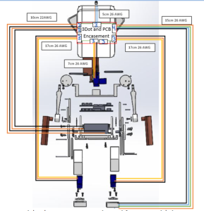
Figure 2. Biped Cable.
Here on this image, we see the Cable tree which corresponds to the final design we have for the Biped. Since the “body servo” was removed, we have removed on set of cabling leading to one of the servos in the center of the figure right below the head. Our wire lengths and type for the servos correspond to the wires that our already on the servos. The cables for the servos are routed out of the head encasement and directly to the servos through a path between the legs. The wires for the color sensor that leads to the foot was the only set that was hand soldered and routed.
Conclusion
The interface definition and cable criteria are described above according to the design for the final Biped.


