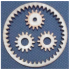
Written by Railan Oviedo (Manufacturing)
Objective
For the Pete-Bot’s (P-Bot) method of movement, our project has implemented a
planetary gear system that incorporates the incline gear as the wheel and 3 planetary gears. The top planetary gear will be the driving gear that is connected to the GM6 motor, while the other two planetary gears will have ball bearings inserted into them—effectively making their presence their solely for the purpose of properly spacing the incline gear. In order to ensure the whole structure stays together, washers will be placed to prevent them from touching the chassis, and a triangular gear holder will be utilized to prevent the system from popping off the chassis.
Preliminary
For a planetary gear system to work, specific parameters must be made in order to ensure the gears can smoothly spin together. The equations to ensure this are as follows:

“N” represents the number of teeth for the incline gear ring, the planetary gears, and the sun gear. As stated in the introduction, the sun gear will not actually be implemented, but it is still necessary for designing purposes. The variable “r” is for the ratio of revolutions between the sun gear and the incline gear.
The Pitch Diameter “PD” is the effective diameter of the gears, and it is determined by multiplying the number of teeth by the gear module “M.” The modules must be the same for all the gears in the system in order for them to operate smoothly.
Test 1
The initial “r” value chosen for the system was 3, so the sun gear would spin 3 times for every spin of the incline gear. The modules have been set to 1, so the number of teeth also determines the pitch diameter in millimeters. For the first trial, the incline gear was chosen to have 40 teeth – thus resulting in a 40 mm pitch diameter – with an outer diameter of 45 mm. From the equations, the other parameters were found as the following:

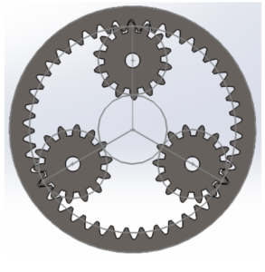
With this, SolidWorks was used in order to generate a simulation for the gears.
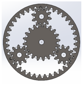
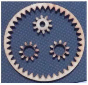
Because of the ball bearings, the lower planetary gears will have an increased inner diamater of 1/4 of an inch. This system was laser cut in order to rapid prototype with the P-Bot chassis.
Gear Holder
The gear holder was made to fit the shape of the first gear system. The design is shown in the picture below:
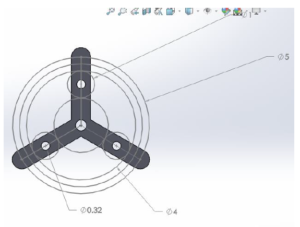
The measurement numbers are given in centimeters. The 4 cm diameter circle represents the pitch diameter of the incline gear, and the 5 cm diameter circle reqpresents the total diameter of the wheel including the tire treads.
Test 2
After testing how the ring actually functions on the chassis, it was seen that the planetary gears for the ball bearings are incredibly flimsy. Furthermore, the wheel is not large enough to surpass the bottom of the chasis, as shown in the picture below:

Due to this, a new system that utilizes a 42-teeth incline gear with “r” equal to 4 was used in order to increase the diameter of the wheel. From the equations, the other gears’ teeth were found as:

Since the planetary gears will now have a wider pitch diameter, this should eliminate the issue of their stability for the ball bearings. Using this, another SolidWorks model was made, and these were also laser cut for rapid prototyping.

Results
After trying the alignment pattern of the gears for Test 2, it was found that the incline gear ring would not touch the driving planetary gear due to the fact that the incline gear becomes slightly raised when it is placed on the ground.
However, when attempting to use the 14 teeth gears in tandem with the alignment for Test 1 (Refer to Image 1), it was discovered that the gears were very close to being in the perfect spots for the whole system to function properly. Minor tweaks would need to be made on this alignment in order to get the positioning correct.
Test 3
The third and final test was to adjust the alignment from Image 1, and to then use the 14 teeth gears in place of the actual gears that should be used for it (i.e. 10 teeth planetary gears, and 20 teeth sun gear).
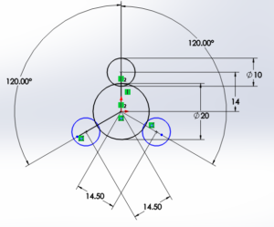
The original distance between a planetary gear and the sun gear was 15mm. This distance is reduced in the hopes of having the incline gear ring fit. To test whether this would work, the alignment pattern was cut out onto wood via a laser cutter.

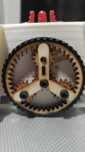
The gear holder was also altered to fit this new alignment. The sides were made thinner so it is possible to see the gears behind it, and a slit was added to one side in order to indicate which side connected to the driving planetary gear. This side was also made slightly longer than the others in order to accommodate the fact that the incline gear slightly rises when it is on the ground.

After laser cutting out the gear holder, the alignment pattern was tested and confirmed to work extremely well. Small washers were put in place between the wooden plate and the gears, and between the gears and the gear holder. These washers were small enough so that they only come into contact with the bearings inserted into the gears, thus resulting in a very small amount of friction when trying to spin the incline gear. The assembled pattern and a reference video are given below:

D-Gear
Although the alignment was set, it now became necessary to change the driving planetary gear so that it fits the shape of the new GM6 motor shaft, which has a D-shaped profile. The model for this gear is given below:

With the alignment set and the D-Gear created, it was then implemented onto the chassis itself, and can be seen as:
References
[1] Reference One
