By: Ryan Nguyen (MST Engineer)
Verified By: Ernie Trujillo (Project Manager)
Approved By: Miguel Garcia (Quality Assurance)
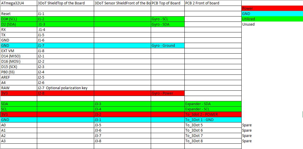
The interface matrix shows how each subsystem of Goliath connects to the ATmega32U4 microcontroller. The top header consists of the sub-systems, the left column has the name and pin number of the ATmega32U4. The matrix maps out how each pin is connected.
From the ATmega32U4, the version 6x 3 dot board specifies 16 pins that students can use for their robots. The first matrix shows the two PCBS of Goliath that will be connected to the three dot board, the top header shield, and the front sensor shield.

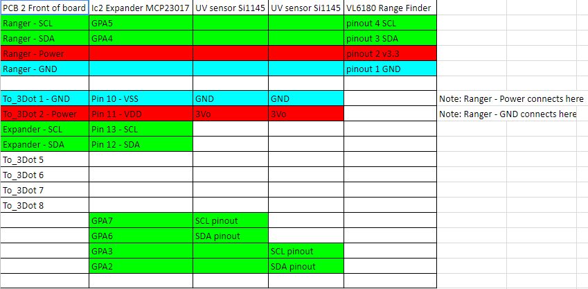
The second matrix shows how the components of the sensor shield will be connected; Goliath uses two UV sensors, as well as a range finder to navigate the maze.

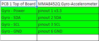
Lastly, Goliath uses a gyrometer, connected to the top PCB, to determine turning in the maze.

