[av_one_full first min_height=” vertical_alignment=” space=” custom_margin=” margin=’0px’ padding=’0px’ border=” border_color=” radius=’0px’ background_color=” src=” background_position=’top left’ background_repeat=’no-repeat’ animation=”]
[av_textblock size=’35’ font_color=” color=” av-medium-font-size=” av-small-font-size=” av-mini-font-size=” admin_preview_bg=”]
IloMilo/Spring/2020
[/av_textblock]
[av_hr class=’default’ height=’50’ shadow=’no-shadow’ position=’center’ custom_border=’av-border-thin’ custom_width=’50px’ custom_border_color=” custom_margin_top=’30px’ custom_margin_bottom=’30px’ icon_select=’yes’ custom_icon_color=” icon=’ue808′ font=’entypo-fontello’ admin_preview_bg=”]
[av_textblock size=’30’ font_color=’custom’ color=” av-medium-font-size=” av-small-font-size=” av-mini-font-size=” admin_preview_bg=”]
Structural Integrity – Internal Joystick Design
[/av_textblock]
[av_textblock size=” font_color=’custom’ color=’#bfbfbf’ av-medium-font-size=” av-small-font-size=” av-mini-font-size=” admin_preview_bg=”]
Author: Farland Nguyen
[/av_textblock]
[av_hr class=’short’ height=’50’ shadow=’no-shadow’ position=’left’ custom_border=’av-border-thin’ custom_width=’50px’ custom_border_color=” custom_margin_top=’30px’ custom_margin_bottom=’30px’ icon_select=’yes’ custom_icon_color=” icon=’ue808′ font=’entypo-fontello’ admin_preview_bg=”]
[av_textblock size=” font_color=’custom’ color=’#bfbfbf’ av-medium-font-size=” av-small-font-size=” av-mini-font-size=” admin_preview_bg=”]
[/av_textblock]
[av_heading tag=’h1′ padding=’10’ heading=’Introduction ‘ color=” style=” custom_font=” size=” subheading_active=” subheading_size=’15’ custom_class=” admin_preview_bg=” av-desktop-hide=” av-medium-hide=” av-small-hide=” av-mini-hide=” av-medium-font-size-title=” av-small-font-size-title=” av-mini-font-size-title=” av-medium-font-size=” av-small-font-size=” av-mini-font-size=”][/av_heading]
[av_textblock size=” font_color=” color=” av-medium-font-size=” av-small-font-size=” av-mini-font-size=” admin_preview_bg=”]
Movement begets character. A simple shake of the head, the idle machinations of the hands can yield an infinite amount of expression. Our project strives to achieve some sort of movement to create personalities for our robots. Otherwise, this project would be visually boring as two bots navigating a grid with stiff exteriors doesn’t really catch the eye. Also, considering that to find each other in a grid of obstacles of varying height, the bots will need to vertically move a section that contains the time of flight sensor to allow the sensor to acquire height readings. To achieve these requirements, we were inspired by Alonso Martinez’s bots to use an internal joystick to create the movement for our bots since he used an internal joystick to achieve the same movements we needed. The joystick would be housed in the torso section of the chassis and would move the head section of the chassis. Fulfilling this task required several different design iterations that will be covered below.
[/av_textblock]
[av_heading tag=’h1′ padding=’10’ heading=’Baseplate: Thingiverse Joystick’ color=” style=” custom_font=” size=” subheading_active=” subheading_size=’15’ custom_class=” admin_preview_bg=” av-desktop-hide=” av-medium-hide=” av-small-hide=” av-mini-hide=” av-medium-font-size-title=” av-small-font-size-title=” av-mini-font-size-title=” av-medium-font-size=” av-small-font-size=” av-mini-font-size=”]
Stuff we will put here woohoo…
[/av_heading]
[av_textblock size=” font_color=” color=” av-medium-font-size=” av-small-font-size=” av-mini-font-size=” admin_preview_bg=”]
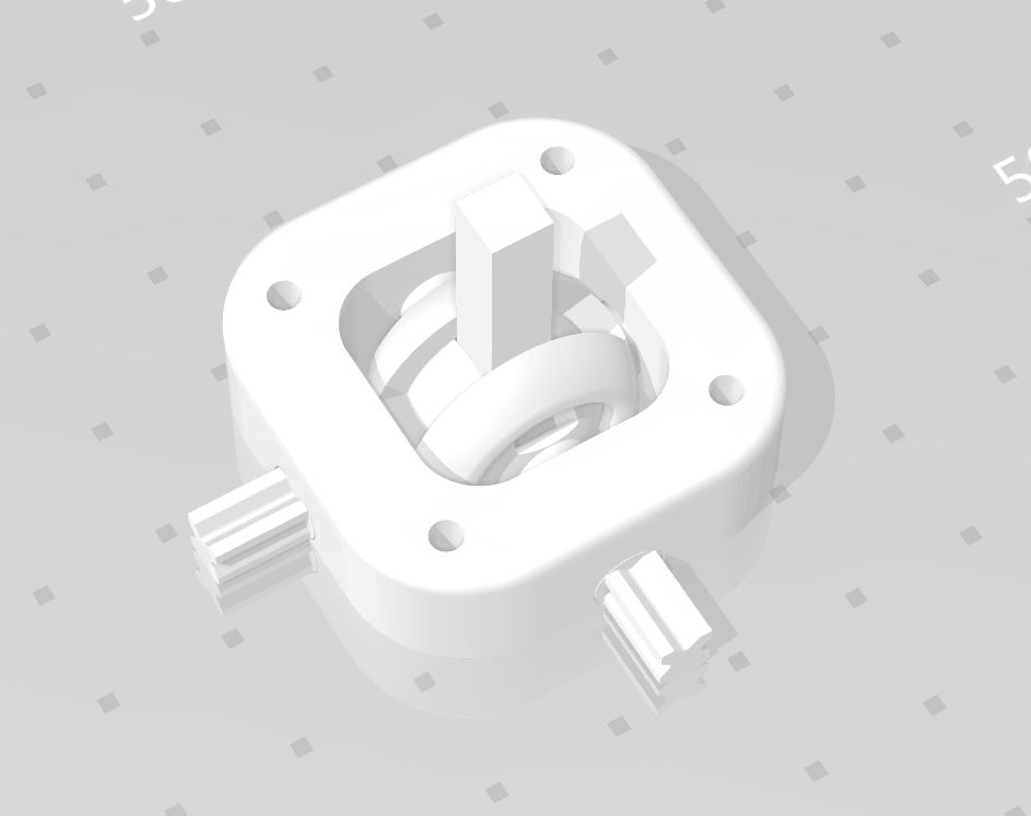
Since our project was basically from scratch and no other previous project had tackled an internal joystick before, we required a fast prototype of a joystick as a proof of concept. It would be used to not only show how the joystick would be used but, if successful, actually implemented into the bots. The first joystick design I turned to was Alonso’s design, seen in Figure 2. However, seeing as he hadn’t posted any files online, I looked to more available, pre-built designs. Thingiverse is a website where users post files of designs that are 3D printer ready the instant they are downloaded. Figure 1 shows the joystick I found on Thingiverse. I chose this design mainly due to the designer advertising that the joystick could be printed in the configuration shown and not in separate pieces as well as how small the joystick was, allowing it to easily fit over the Paperbot drivetrain.
However, once printed out, this joystick turned into a major hassle. By this time, we had also settled on using SG90 micro-servos, which this joystick had no concessions for and would have required drastic modifications. The central shaft was also minuscule to the point where weight testing would easily break it off the rest of the joystick. But, the main issue that ruined this joystick’s chances of being utilized was that the joystick was so small that the printer used didn’t have a high enough resolution, thus creating a solid block rather than a moving joystick. At this point, with this prototype down the drain, we became inclined to design our own custom joystick.
[/av_textblock]
[av_heading tag=’h2′ padding=’10’ heading=’Wire Frame: Alonso Martinez’s Joystick’ color=” style=’blockquote modern-quote’ custom_font=” size=” subheading_active=” subheading_size=’15’ custom_class=” admin_preview_bg=” av-desktop-hide=” av-medium-hide=” av-small-hide=” av-mini-hide=” av-medium-font-size-title=” av-small-font-size-title=” av-mini-font-size-title=” av-medium-font-size=” av-small-font-size=” av-mini-font-size=”][/av_heading]
[av_textblock size=” font_color=” color=” av-medium-font-size=” av-small-font-size=” av-mini-font-size=” admin_preview_bg=”]
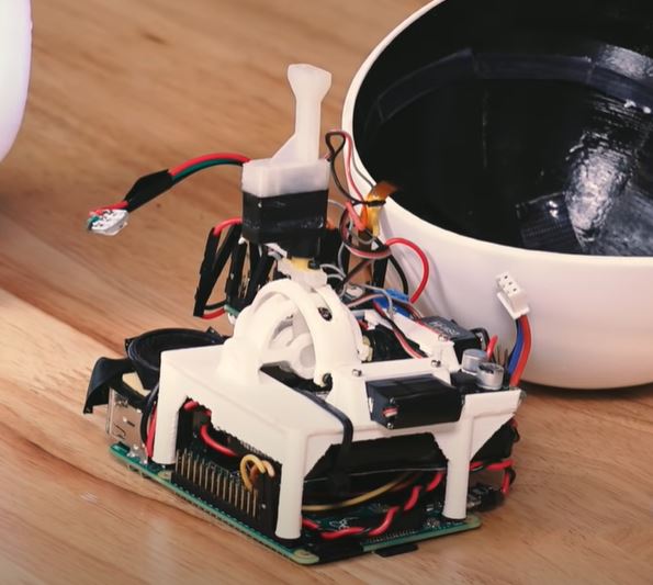
Despite not being readily available, Alonso’s joystick was a major contributor to the design of our custom joystick. Seen in Figure 2, his joystick was a custom design that employed servos to create the head movement of his bot. Considering that we were trying to achieve the same purpose, it would have been a shame to ignore all of his hard work when designing our own custom joystick. Essentially, his joystick design consisted of four things: a base, two joystick axes, and a central shaft. Utilizing the image, I reversed-engineered Alonso’s joystick to the best of my abilities and modified it to meet the dimensions required to fit onto of the Paperbot and inside the chassis torso.
[/av_textblock]
[av_heading tag=’h1′ padding=’10’ heading=’Load Bearing Columns: Custom Joystick Designs’ color=” style=” custom_font=” size=” subheading_active=” subheading_size=’15’ custom_class=” admin_preview_bg=” av-desktop-hide=” av-medium-hide=” av-small-hide=” av-mini-hide=” av-medium-font-size-title=” av-small-font-size-title=” av-mini-font-size-title=” av-medium-font-size=” av-small-font-size=” av-mini-font-size=”][/av_heading]
[av_textblock size=” font_color=” color=” av-medium-font-size=” av-small-font-size=” av-mini-font-size=” admin_preview_bg=”]
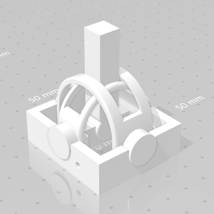
The results of my attempt at reverse engineering can be seen in Figure 3. I mainly simplified Alonso’s design while still trying to keep it small enough to stay on top of the Paperbot. This joystick would be separated into four different parts since I wasn’t willing to risk the same issues as the Thingiverse joystick. Since the design was simple, the assembly of the joystick wouldn’t be that difficult anyway. I would also bulk up the axes and the main shaft in a preemptive act to support more weight than the Thingiverse attempt.
Once printed, this joystick would showcase a definitive improvement over the Thingiverse joystick. Weight testing showed that it could support the weight of the chassis head. Attaching the SG90s were a breeze with the use of superglue and the accompanying servo horns. Most importantly, this joystick wasn’t designed to be printed in place and would move rather easily once assembled. This joystick would achieve its purpose as a proof of concept as it was integrated with the servos to provide yaw and pitch dimensions. Yet, it would require some improvement as excessive and rapid servo movement would cause either the axes or the main shaft to pop out of their sockets. At this stage, we had agreed upon the vague silhouette of the chassis that rendered this design obsolete, requiring another iteration.
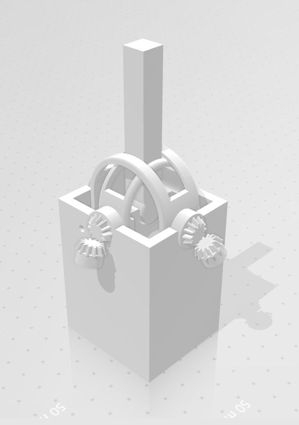
The chassis torso, which would hold the joystick, consisted of a tapered cylinder. Maximizing the amount of yaw and pitch required the joystick to have an extended base to reach a height outside of the cylinder. Seen in Figure 4, the base and main shaft were extended and the socket tolerances tightened to decrease slippage. In the interest of saving space, I would also turn to bevel gears. These gears would allow me to place the SG90 servos in a vertical configuration rather than the horizontal configuration I was using. Once printed, I would immediately test to see if this joystick could support the chassis’ head. Once this test was satisfied, I began to implement the servos with the bevel gears. I immediately ran into issues as my bevel gears couldn’t provide the torque required of them to move the joystick. These gears also couldn’t provide the level of accuracy in movement to allow for fine tuning of the joystick. I would move to address these complications in the final iteration.
[/av_textblock]
[av_heading tag=’h2′ padding=’10’ heading=’Roofing: Finalized Custom Joystick Design’ color=” style=’blockquote modern-quote’ custom_font=” size=” subheading_active=” subheading_size=’15’ custom_class=” admin_preview_bg=” av-desktop-hide=” av-medium-hide=” av-small-hide=” av-mini-hide=” av-medium-font-size-title=” av-small-font-size-title=” av-mini-font-size-title=” av-medium-font-size=” av-small-font-size=” av-mini-font-size=”][/av_heading]
[av_textblock size=” font_color=” color=” av-medium-font-size=” av-small-font-size=” av-mini-font-size=” admin_preview_bg=”]
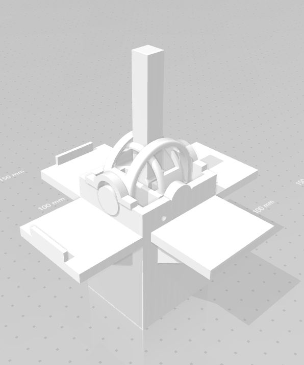
With saving space as a major concern and my bevel gear attempt yielding nothing but problems, I rationalized that to save the joystick, I would make it larger. That meant that something would have to sacrificed; in this case, the chassis head would have some of its lower material removed. This removal opened up abundant real estate that I capitalized upon. Seen in Figure 5, the largest modification to the joystick was the replacement of the bevel gears with four horizontal platforms. I turned back to the original horizontal placement as it was simpler than the vertical placement and would provide a higher level of movement accuracy without any complicated mechanisms. The four platforms allowed the horizontal placement to occur and were designed to fit as close to the top of the chassis torso as possible. I would also add in two covers on top of the axes’ sockets to stop any potential pop outs from the axes. Once printed, this joystick performed up to expectations considering that it easily achieved the set requirements as well as resolving all of the issues from the previous design iterations.
[/av_textblock]
[av_heading tag=’h1′ padding=’10’ heading=’References/Resources’ color=” style=” custom_font=” size=” subheading_active=” subheading_size=’15’ custom_class=” admin_preview_bg=” av-desktop-hide=” av-medium-hide=” av-small-hide=” av-mini-hide=” av-medium-font-size-title=” av-small-font-size-title=” av-mini-font-size-title=” av-medium-font-size=” av-small-font-size=” av-mini-font-size=”][/av_heading]
[av_textblock size=” font_color=” color=” av-medium-font-size=” av-small-font-size=” av-mini-font-size=” admin_preview_bg=”]
- https://www.thingiverse.com/thing:2156713
- https://www.youtube.com/watch?v=0vfuOW1tsX0
[/av_textblock]
[/av_one_full]