Watchdog Timer
The Basics
Table of Contents
Reference(s):
Material in this document was drawn from these three sources
- Watchdog Timer Basic Example, Written by Nicolas Larsen, 10 June 2011
- ATmega48PA/88PA/168PA/328P Section 10.8 Watchdog Timer (page 50 / 448)
- ATmega16U4/ATmega32U4 Section 8.2 Watchdog Timer (page 48 / 448)
- Standard C library for AVR-GCC avr-libc wdt.h library
- You can find the wdt.h file in the Arduino\hardware\tools\avr\avr\include\avr folder
Introduction
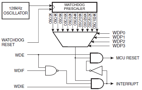
 The watchdog timer watches over the operation of the system. This may include preventing runaway code or in our C example, a lost communications link.
 The watchdog timer operates independent of the CPU, peripheral subsystems, and even the clock of the MCU.
 To keep the watchdog happy you must feed it a wdr (watchdog reset) assembly instruction before a predefined timeout period expires.
 The timeout period is defined by a ~128KHz watchdog timer clock and a programmable timer.
Watchdog Timer Reset
“In normal operation mode, it is required that the system uses the WDR – Watchdog Timer Reset – instruction to restart the counter before the time-out value is reached. If the system doesn’t restart the counter, an interrupt or system reset will be issued.” ATmega328P Datasheet Section 10.8.2 Overview
When the Watchdog Reset (wdr) instruction is encountered (pun intended), it generates a short reset pulse of one CK cycle duration. On the falling edge of this pulse, the delay timer starts counting the Time-out period tTOUT.
Watchdog Timer Module
To configure the watchdog timer you define the timeout period by setting the pre-scale value, and define action to be taken if a timeout occurs.
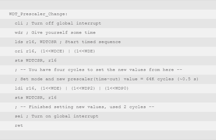
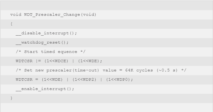
Configuration bits are found in the WDTCSR – Watchdog Timer Control Register. Before you can change the WDE and/or prescaler bits (WDP3:0), the WDCE – Watchdog Change Enable bit must be set.
Define Timeout Period
The WDP3..0 bits determine the Watchdog Timer prescaling when the Watchdog Timer is running. The different prescaling values and their corresponding time-out periods are shown here.
On your own…
How many flip-flops are needed to implement the watchdog prescaler?
Hint: How many bits are needed to generate the longest delay with an input clock frequency of 128KHz?
Define Timeout Action
The Watchdog always on (WDTON) fuse, if programmed, will force the Watchdog Timer to System Reset mode. With the fuse programmed (WDTON = 0) the System Reset mode bit (WDE) and mode bit (WDIE) are locked to 1 and 0 respectively. Arduino / ATmega 328P fuse settings.
The Arduino ATmega328P bootloader sets the fuse to unprogrammed WDTON = 1, which means you can program the action to be taken by setting or clearing the WDE and WDIE bits as shown in the following table.
Note: 1. WDTON Fuse set to “0” means programmed and “1” means unprogrammed.
Watchdog Timer is in Interrupt and System Reset Mode – When the interrupt occurs the hardware automatically clears the WDIE bit, thus putting the watchdog timer into the “System Reset” mode, as defined in the table (WDTON = 1, WDIE = 0, WDE = 1). At the next timeout, a reset is generated.
Watchdog Setup
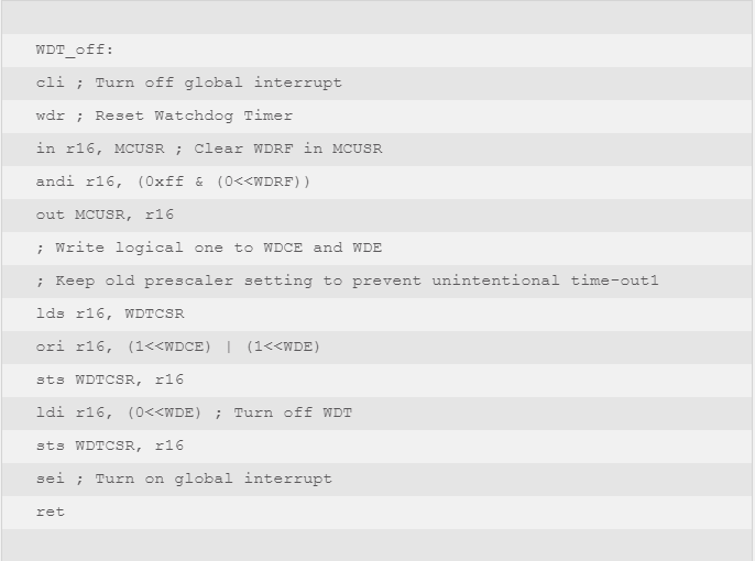
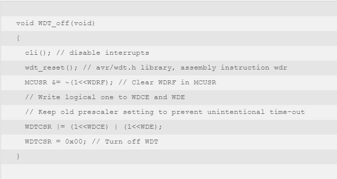
Turning Off the Watchdog Timer
3DoT Watchdog
Setup
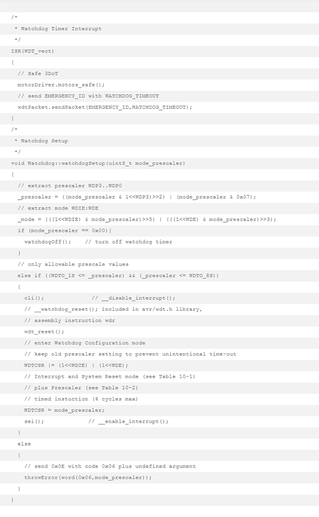
In the watchdogSetup C++ program the WDTCSR register is configured to operate the watchdog timer in the “Interrupt and System Reset” or “Interrupt” mode, with a programmable delay from 1 to 8 seconds.
To configure the WDT a 0x10 WATCHDOG_SETUP command packet is sent with one of the following arguments.
|
Argument
|
Mode
|
Timeout
|
|
0x00
|
Watchdog Off
|
|
|
0x4E
|
Interrupt and System Reset
|
1 sec
|
|
0x4F
|
2 sec
|
|
|
0x68
|
4 sec
|
|
|
0x69
|
8 sec
|
|
|
0x46
|
Interrupt Only
|
1 sec
|
|
0x47
|
2 sec
|
|
|
0x60
|
4 sec
|
|
|
0x61
|
8 sec
|
0x0E Exception CodesIf one of these arguments is not sent the program sends a 0x0E “Exception” packet with a 0x06 “Watchdog timeout out of range” code. To put this in perspective, here are all the Exception codes and what they mean.
| High | Low Order Byte |
| 01 | Start byte 0xA5 expected |
| 02 | Packet length out of range 1 – 20 |
| 03 | LRC checksum error |
| 04 | Undefined command decoder FSM state |
| 05 | Array out of range i >= 23 |
| 06 | Watchdog timeout out of range |
Timeout
If programmed for 8 second “Interrupt and Reset” Mode and a “WDR” command packet is not sent within the timeout period, an interrupt will occur at T+8 seconds and system reset at T+16.
When the interrupt occurs T+8 seconds the hardware automatically clears the WDIE bit, thus putting the watchdog timer into the “System Reset” mode (WDTON = 1, WDIE = 0, WDE = 1).
- A 0x0B “Emergency” telemetry packet with 0x0100 code is sent.
0x0B Emergency Code
High Low
01   00  Watchdog timeout
- After this interrupt, at any time (up to T+16) you can reset the timer, turn it off, change modes, etc.
Demonstration
- Plug in an Arduino UNO
- Launch and Configure CoolTerm
- Launch arxrobot_firmware_3DoT
- Normal Operation
A5 02 10 69 DE    Set watchdog interrupt for 8 sec
A5 01 11 B5       Ping (repeat at a frequency of less than 0.125 seconds)
CA 01 11 DA       Pong
A5 02 10 00 B7    Turn Watchdog Off
• Timeout Example
A5 02 10 4E 59     Set watchdog interrupt for 1 sec
CA 03 0B 01 00 C3  Emergency Code 0B, Watchdog timeout 0100
CA 03 06 00 63 AC  Read and transmit sensor values after restart
CA 03 02 00 00 CB
• Timeout Prescaler out-of-range
A5 02 10 62 D5     ATmega reserved
CA 03 0E 06 62 A3
      ↓   |  ↓
exception |  argument
error     ↓
watchdog timeout out of range
3DoT C++ Watchdog Object
The 3DoT Watchdog object has only one public method
void watchdogSetup(uint8_t);
The 3DoT Watchdog object has two private methods
void watchdogOff();
void throwError(uint16_t);
The 3DoT Watchdog object has three read-only private properties
uint8_t _prescaler;
uint8_t _mode;
uint8_t _counter;
In the next section we take a closer look at the watchdogSetup method.
3DoT Watchdog C++ Code
Review Questions
- TBD
Answers
Using your mouse, highlight below in order to reveal the answers.
- TBD

