By: Victoria Osaji, Manufacturing and Development Engineer
Introduction:
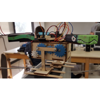
After a lot of trial and error and prototyping, we have the basis for our mechanical design. Listed below we explain how we achieved each part.
Level 2 Subsystem below:
3. 3rd Generation Velociraptor (Th) should resemble a Velociraptor of the Theropodous Dinosaur Suborder that is scaled down to below the height of the columns in the game.
8. 3rd Generation Velociraptor (Th) shall use a single servo to control the head and tail.
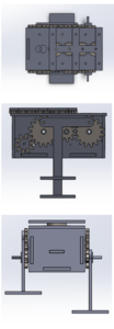
Figure 1: These are different views of our robot without the head and tail.
Body:
The body of the robot was designed with a couple of things in mind. We knew we wanted all the components such as the 3DOT board, PCB, the 2 servos and the 2 GM9 motors to be able to fit within the body so we made the robot approximately about 100mmx52mmx48mm. The thickness was based on the wood we used which was Balsa and it was .3175mm thick.
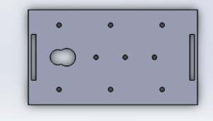
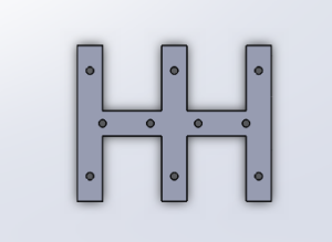
Figure 2: This is a top view of our chassis. The biggest hole is the hole for where the servo is located.
On the top chassis, we designed a hole about 13mm for one of the servos that is going to be connected to the gear train that will move the head and tail [L2-8]. We made that hole because we wanted all of our gears to be flush on the body and we were able to achieve that with the hole of the top.
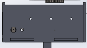
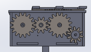
Figure 3: This is a side view of our robot. The biggest hole is the hole for the GM9 motor the other three holes at the top in a row are for the gears.
On the side chassis, we have different holes for the gear train 3mm that will be controlling the legs and the hole for the motor couplers that connect to the GM9 motors were 7mm.
Figure 4: This is the cover that went over the head and tail to keep the gears flush on the top.
On top of the top chassis we have a piece that was created to hold the gears in place and this piece consist of ten 3mm holes. The body was designed to be pressure fit to avoid using adhesive hence why there are cut of rectangles on certain pieces and extruded rectangles on others so they can mate into each other.
Gear Train:
Figure 5: This is gear train for the legs on Solidworks.
The big gears have 16 teethes and the small ones have 10 teethes. Two big gears and 2 small gears will be used to make a gear train for our mechanical systems. The big gears have 3mm holes in them so they can be connected to the legs. Calculations had to be done to determine the gear ratios. (Click here hyperlink to blog post)
Motor couplers:
Figure 6: These are the small gears also known as the motor couplers for the GM9s and the rotary sensors.
The motor couplers were made to be connectors from the GM9 motors to the rotary sensors to the legs. They were made in form of gears because we need the motor to drive the gear train for the legs to move. On one side of the motor coupler we have an extruded cut piece 6mmx5mmx3mm to fix the GM9 motor and on the other side we have an extruding shaft for the rotary sensor. It was a circle with a diameter of .125mm cut in a shape of a “D”. This motor coupler goes into the small hole of the side chassis.
Legs:
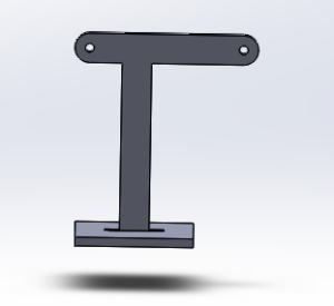
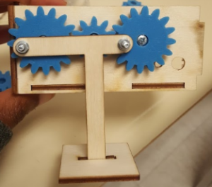
Figure 7: This is the final design for the legs.
The final design for our legs was two links connected in a “T” shape with a square platform as the foot. The links are about 15mmx 54mm with 3mm holes. The holes on the legs are connected to the smaller holes on the big gears. The project manager, Paul actually came up with this design because it would be easy to control on the electrical side. We had about 3 other leg designs before we came to this one. Click here to see the leg journey.
Head and tail:
Figure 8: To the left is the piece that we used for the head and tail. To the right is the gear train for the head and tail.
The head and tail design was motivated by the requirement to use a single servo to drive the head and tail. The design was simply a gear with 9 teethes on one half and the other half of the circle or gear was elongated about 50 mm into a flat board (.00125mmx.00075mmx.00025mm) for our battery holders (like the picture to the left). Then in between the head and the tail were two small gears with 20 teethes each.
Materials:
Figure 9: These are the materials we ending up using, balsa wood and PLA Filament plastic.
At first we wanted to 3D print our whole robot but we when we prototyped our robot leg with laser cut wood we really liked the appearance of it. Then we processed to laser cut the body just to test it out and we really liked it. We liked how precise it was and the ability to pressure fit with it as oppose to 3D printing. We had a lot of issues 3D printing because I would design something and the 3D printer would print it but the part would shrink or wouldn’t fully print certain parts especially if they were small parts. With laser cutting I was able to design the part with exact dimensions because the laser cutter was very exact. We still 3D printed the gears and the motor couplers because those parts are 3D and the laser cutter only cuts in 2D.
(Link to material trade off study blog post)
Conclusion:
All in all, these are the major things that helped our project come together. This design is simple and it work. T he thing I learned the most is rapid prototype early and have back-ups. Just because something works on solidworks doesn’t mean it is going to work in the physical world. It might be frustrating but when it all comes together trust me, it will all be worth it. Good luck!
