By: Jordan Smallwood (PM)
Approved By: Miguel Garcia (Quality Assurance)
Table of Contents
Pathfinder Team:
Jordan Smallwood (PM)
Diane Kim (E&C)
Mohamad Yakoub (MST)
Adolfo Jimenez (Manufacturing)
Executive Summary:
By: Jordan Smallwood (PM)
Mission Objective:
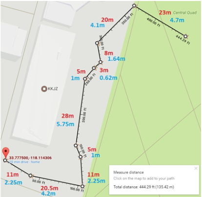
Figure 1: Final Course Outline
The Spring of 2018 Pathfinder will follow the path laid down by previous Pathfinders. The mission will begin in front of the CSULB library where the rover will exit its cocoon state. The rover will then proceed to begin its journey through campus, a 0.09 mile journey to its charging station. There will be 10 predefined GPS checkpoints along the way and the rover will traverse a flight of stairs. Once the rover has arrived at the charging station it will begin to track the sun and provide the Arxterra user with up to date battery level conditions. Specifically the Pathfinder will demonstrate the following:
- Custom solar panels capable of tracking the sun and exhibiting optimum orientation so that battery charge takes the least amount of time.
- The rover will be able to enter and exit a cocoon state. The term cocoon state implies that the solar panes will fold up so that in the event of a dust storm the solar panels will not become damaged. This state will be entered if the rover is in launch, a dust storm or whenever the rover is operating over steep terrain.
- The rover will be able to communicate with the Arxterra app providing information like battery level, panel angles, panel voltages and charging current.
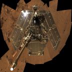
- The solar panels will have a form factor identical to those of the Spirit and Opportunity Mars Rovers.
- The rover will exhibit a 6-wheel slip differential for turning and traversing rough terrain. Since the robot will be climbing over random objects, some wheels will not require the same speed as other wheels and this needs to be considered while operating the rover.
- Demonstration of GPS navigation with obstacle avoidance.
- The course mapped out by F’16 and S’17 will be the same course for S’18.
- There shall be no modification to the rover that stands in the way of high desert operation.
Project Requirements:
By: Jordan Smallwood (PM)
Level 1 Requirements:
- The pathfinder shall travel a 0.09 mile course. This course includes going up a set of 3 stairs at a 45 degree incline and another set of 3 stairs with a decline of 45 degrees.
- Pathfinder should launch from a cocoon state
- The Pathfinder should enter and exit the cocoon state by Arxterra app user input.
- Pathfinder shall allow the user to enter the “articulate state” program module which should be available once the Pathfinder has exited its cocoon state. This sequence should direct the solar cells at the proper orientation to allow max charge of the battery.
- The Pathfinder shall update the user with information about GPS location, battery level and charge current when in the “Articulate state”. The Pathfinder should update the user with panel angles.
- The overall solar panel system will be a scale model of the Spirit and Opportunity Mars and Rovers.
- No design decision shall preclude operations in a high desert environment. (Amboy, California)
- The Pathfinder will use high-side detection and correction. Consequently, wheels under a no-load condition shall be considered and power to that motor shall be decreased.
- A 6-wheel electronic slip differential shall be implemented.
- The Pathfinder should demonstrate obstacle avoidance while making its journey through campus using the ultrasonic sensors.
- Rocker bogie mechanism shall be improved by implementing and operationally verifying a differential gear-box system as opposed to the differential bar.
- The Pathfinder shall be designed for easy assembly and disassembly.
Level 2 Requirements:
1.1: The power budget and battery will meet the requirement of the determined course. The actual distance traveled shall be used to verify the requirement.
1.2: In order to travel up these stairs our mass report along with our motor mock up shall verify that this can be accomplished.
2.1: To perform the cocoon state function the solar panels will be mounted to worm gears attached to DC stepper motors to ensure smooth operation.
3.1: The Pathfinder should communicate via Bluetooth with the Arxterra user and should have an interface allowing the user to enter/exit the cocoon state.
4.1: The articulate state module should adjust the positions of the solar cells using a proportional controller.
4.2: The proportional controller should accept the charge rate as an input and should output changes in orientation.
5.1: While communicating with the user via Bluetooth on the Arxterra app the Pathfinder shall respond with packets of information related to this information
6.1: The side and rear panels shall be capable of position orientation to enter and exit the cocoon state and also optimize battery charge.
6.2: The solar panels should enter the cocoon state when the Pathfinder falls.
7.1: These panels will be constructed of aluminum such that the rover can operate in the harsh desert conditions typical of Mars.
8.1: A software program shall be used ensuring that the wheels are spinning at the same rate.
8.2: Shaft/Rotary encoders shall be used to determine the speed of the wheels
8.3: Current sensors shall be used to determine the load on the wheels
8.4: To conserve energy, the rover shall stop rotation of a freely moving wheel using the current sensors
10.1: The rover should not make any attempt to climb an object that it is unable to clear
11.1: The differential gear box will be constructed of three miter gears, three machined shafts, six mounted bearings and shaft collars.
11.2: This mechanism will be mounted on top of the Pathfinder and enclosed in an aluminum box.
12.1: The design of the aluminum box of the Pathfinder shall be designed for easy access to the electrical components.
System Design:
System Block Diagram:
By: Mohammad Yakoub (MST)
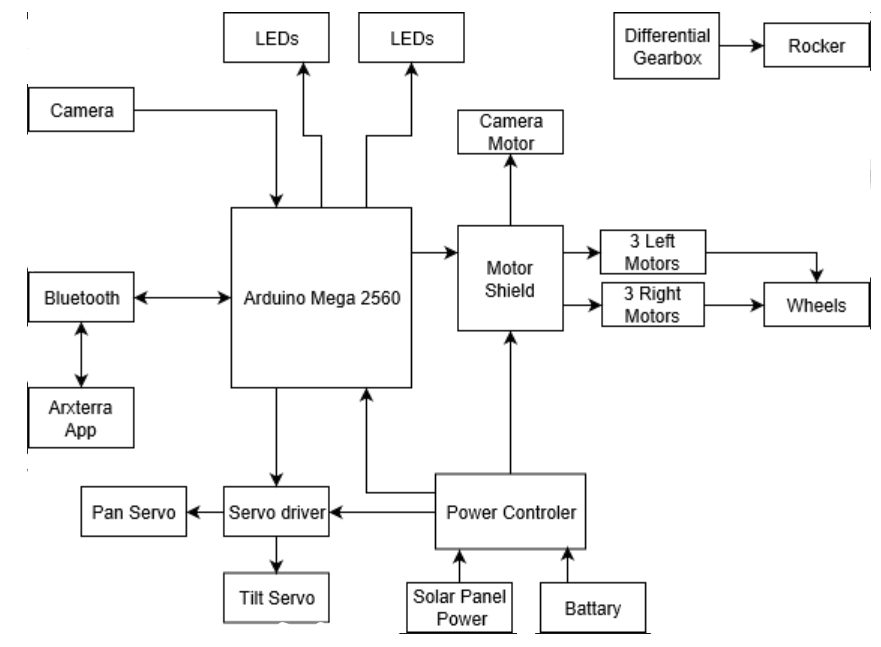
Figure 2: System Block Diagram for Pathfinder Project
The system block diagram describes the overall interconnections of all the peripheral systems. At the heart of the system you will find the Arduino Mega which controls virtually every device in the project. This is controlled via the Arxrobot app through bluetooth communication.
Work Breakdown Structure:
By: Jordan Smallwood (PM)
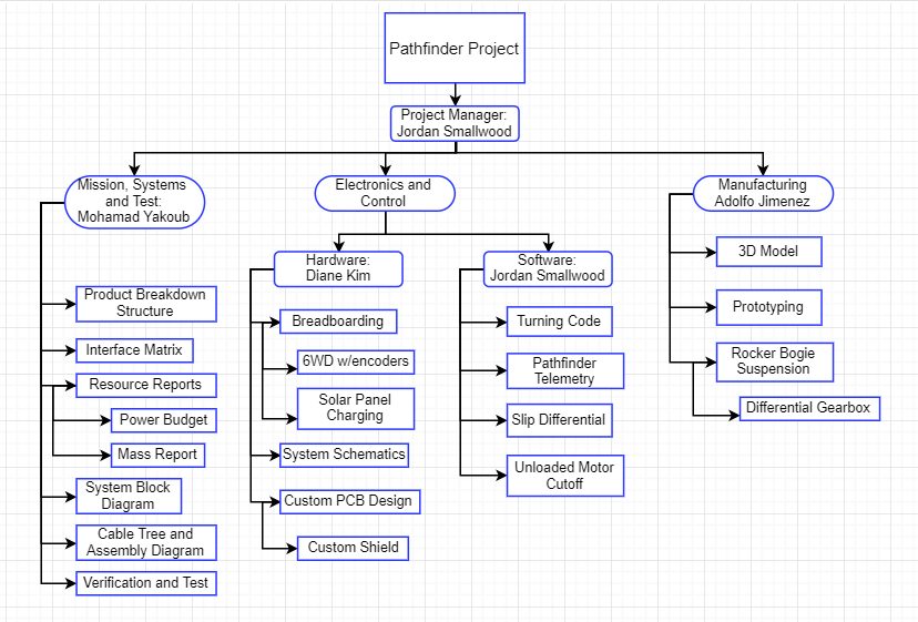
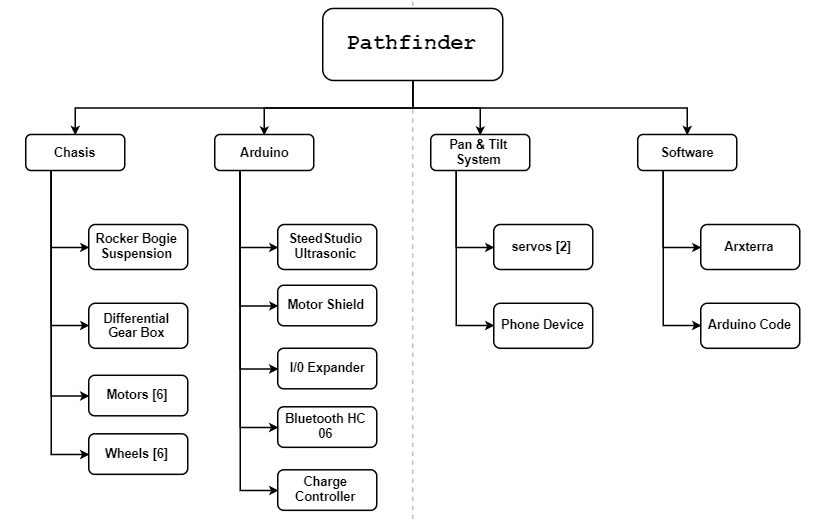
Figure 3: Work Breakdown Structure for Pathfinder Project
The work breakdown structure describes the major responsibilities of each engineer working on the project. The Electronics and Control division has been divided into two main categories, software and hardware. The Manufacturing division was primarily responsible for the overall fabrication of the Pathfinder and detailed SolidWorks model. And finally the Mission, Systems and Test engineer is responsible for the integration of all these different divisions.
Product Breakdown Structure:
By: Mohammad Yakoub (MST)
Figure 4: Product Breakdown Structure for Pathfinder Project
Resource Reports:
Final Power Report:
By: Mohammad Yakoub (MST)
Figure 5: Final Power Allocation Report
Final Mass Report:
By: Mohammad Yakoub (MST)
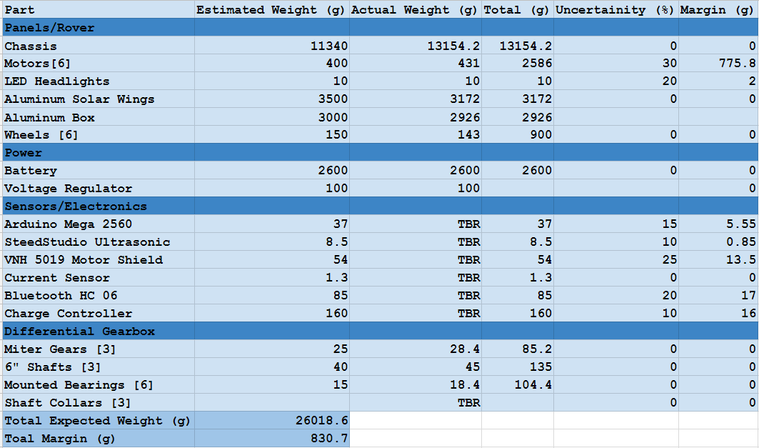
Figure 6: Final Mass Report
Final Cost Report:
By: Jordan Smallwood (PM)
The first cost report includes all purchases that were made by our team for our current project. It does not include cost of material that was purchased from previous semesters.
The second final cost report includes past purchases from previous semesters that were used in the making of our current design.
Interface Matrix:
By: Diane Kim (E&C)
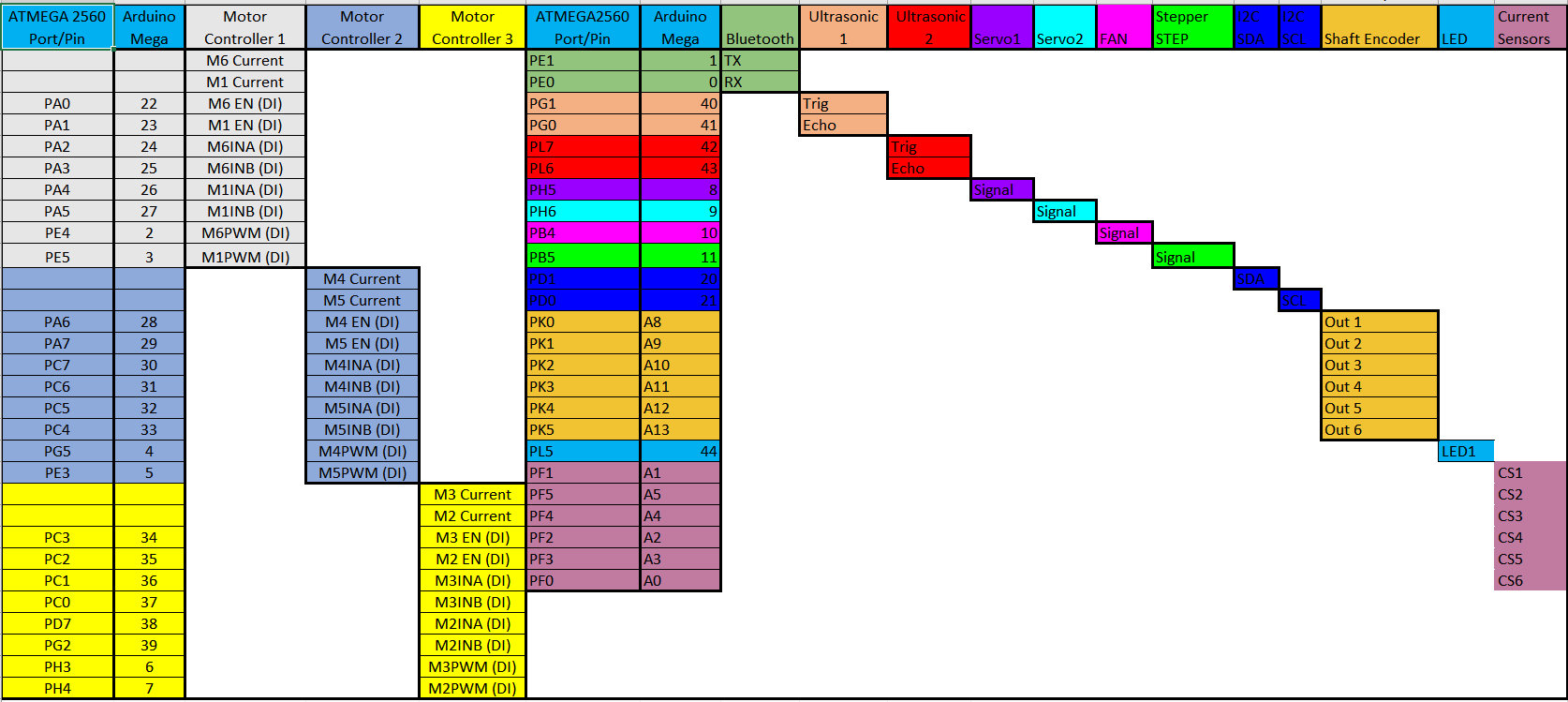
Figure 7: Interface Matrix describing pin location’s of system and peripherals
The interface matrix describes the various signal locations for the Pathfinder’s system diagram. Having a good description of where signals are coming in and out is extremely beneficial throughout the course of project design. Many times throughout the semester this document will be referred to and when coding this can often solve many problems.
Mission Command & Control:
By: Jordan Smallwood
The Pathfinder is connected to the Arxrobot app via Bluetooth communication. In addition, the Arxrobot app is connected to the Arxterra Control Panel to expand the capabilities of the Pathfinder. This method of controlling the phone that controls the rover is ideal for GPS navigation, telemetry, and video feedback without the need for including additional sensors and devices. More information regarding the interconnections is described here.
Software Design:
By: Jordan Smallwood (PM)
No-Load:
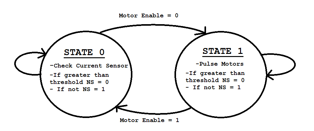
The Pathfinder has been equipped with 6 high-side current sensors capable of detecting current draw up to 5A to each motor. While these sensors are only calibrated for the motors spinning in one direction a level shifter can be implemented such that we can detect up to 2.5A in both directions. These sensors are used to detect whether or not a load is present on the motors. The difficult task is knowing when to turn the motors back on. To do so we had to implement a pulse motor routine that would turn the motors on for a moment and check the current. This was all done with software by inserting a 2-state FSM in a timer interrupt.
Figure 8: No Load FSM
One of the major issues with this technique is that whenever you turn on a motor from an off state the current required to move the shaft is much greater than normal operation. Therefore you have to wait a moment until you can measure the current to allow the motor to stabilize. This technique has been accomplished and more information regarding this concept can be found here.
6 Wheel Electronic Differential:
A six-wheel differential was implemented in software and hardware with the use of pin change interrupts and quadrature hall effect sensors. While pin change interrupts are more tedious to manage, they offer a significant bonus as virtually every pin can be configured to operate in this manner. The Pathfinder will be completing turns as well as traveling over random objects and this is vital to move forward and avoid unnecessary drag on the other wheels. The process involves 6 unique controllers that track a set pulse delay. More information regarding the 6 wheel differential can be found here. And here.
Due to time constraints and non-software related issues, the Pathfinder is currently unable to perform GPS navigation. However, access to GPS information regarding latitude, longitude and heading can be extracted from the Arxrobot application onto the Arduino. Furthermore, these values can be modified to produce distance to checkpoints and required turn. Although this feature is currently not functional it is definitely feasible.
PCB/Hardware Design:
By: Diane Kim (E&C)
Chassis PCB:
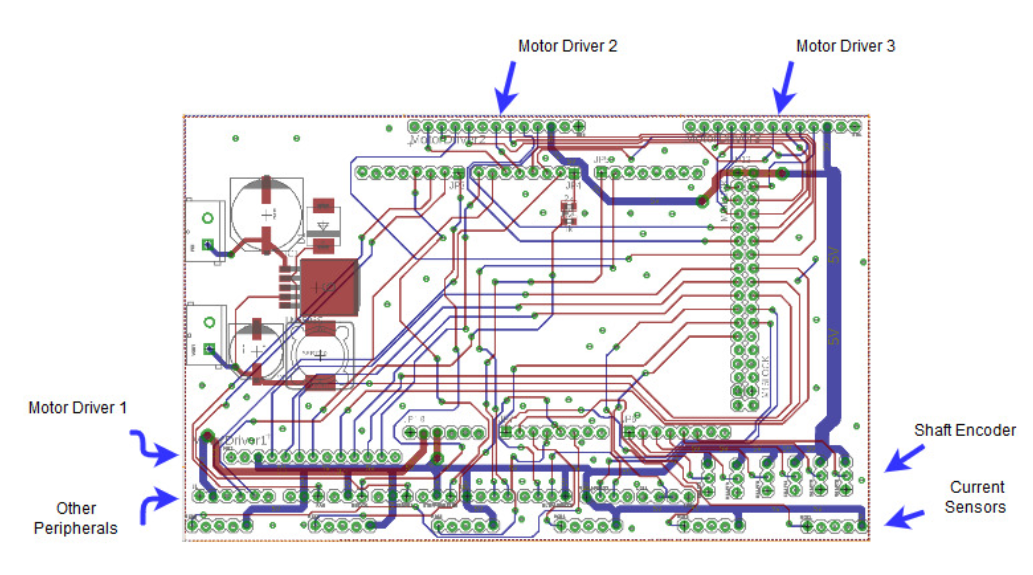
Figure 9: Layout of Final Chassis PCB
The final chassis PCB makes the following connections:
- Motor Drivers (3)
- Motor Current Sensors (6)
- Shaft Encoders (6)
- Ultrasonic Sensors (2)
- HM-10 Bluetooth
- LEDs (2)
- Servos (2)
- Fan
- Stepper Motor Driver STEP
- I2C connection (SDA and SCL)
- LM2596 Buck Converter
For more information regarding the final chassis PCB please visit this link.
Solar Panel PCB:
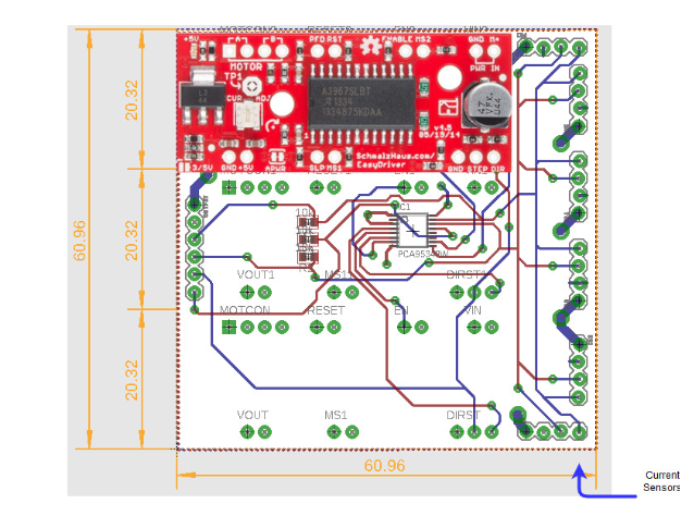
Figure 10: Layout of Custom Solar Panel PCB
The solar panel PCB contains the following systems:
- Current Sensors (6)
- Stepper Motors (3)
- GPIO Expander
For more information regarding the solar panel PCB please visit this link
Final Mechanical Design:
By: Adolfo Jimenez (Manufacturing)
Chassis Design:
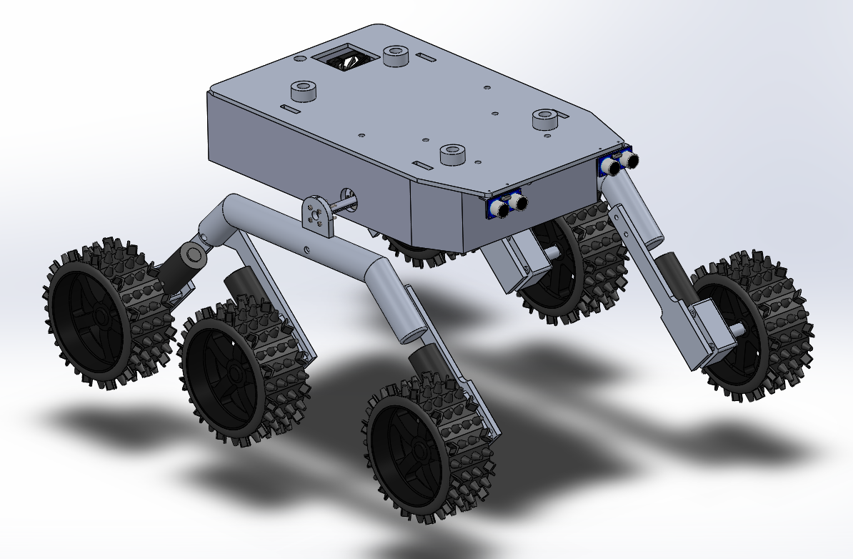
Figure 11: Final Design of Pathfinder
The final chassis design is similar in nature to previous semesters with the exception of a few major upgrades. The previous design had radial bearings on the rocker mechanism which was not properly installed. We have upgraded the design to include the use of thrust bearings since the load is axial.
In addition to the rocker bearings we have installed a gear-box differential to provide fluid motion transfer from one set of wheels to the other. The previous design involving a differential bar seemed to have many issues that were addressed in previous blog posts.
The new chassis also expands the total room for electronics tremendously. The size of the overall box is 14″ x 9″ x 3″. This is plenty of room for proper wiring and placement of electronics.
More information can be found here. ONCE FINAL DESIGN APPROVED NEED TO INCLUDE LINK
Final Solar Panel Design:
When it came time to design the new solar panels many different ideas presented themselves. We considered opening and closing the solar panels with the use of a winch/pulley system, however the customer did not approve. Ultimately we wend with a worm-gear with DC motor system. The issue with this design is that there is no support for the miter gear on the worm-gear.
For more information please visit this blog post.
Verification and Validation:
By: Mohammad Yakoub (MST)
Please refer to the link within the resources section for further information.
Pathfinder Improvements:
By: Jordan Smallwood (PM)
- Rocker’s are free to rotate about the bogie mechanism with the installation of thrust bearings
- Gearbox differential allows rocker-bogie mechanism to move the way it was intended.
- Magnetic hall effect sensors on the motors allow for speed control
- High side current sensors provide a means of determining load on a motor.
- Enlarged electronics box provides shelter for delicate electronics that would otherwise be destroyed in a desert environment.
- DC Fan with filter built into electronics box
- Quick removal of lid for access to electronics
- Power distribution system securely fastened to electronics box with in-line fuse
- Wiring harnesses throughout for a clean design
Experiments Conducted:
- Solar Panel Charging
- Stepper Motor Study
- Motor Mock Up
- Solar Panel Trade-Off Study
- Buck Converter Efficiency
- Ultrasonic Field of View Test
Schedule:
By: Jordan Smallwood (PM)
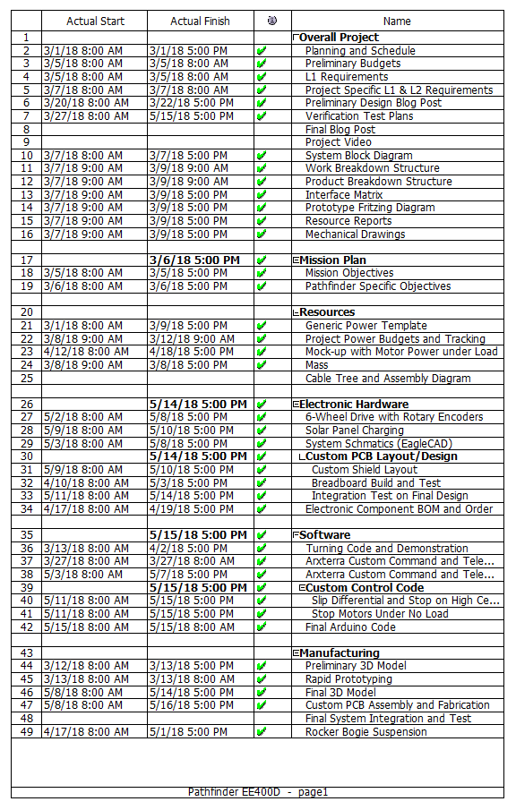
Figure 11: Schedule for Pathfinder Project
Burndown Chart:
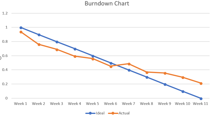
Figure 12: Burndown Chart for Pathfinder Project
The Pathfinder project was one of the largest in terms of what needed to be accomplished and size. Many modifications needed to be made to the Pathfinder before tests could be performed to determine whether or not we would meet our requirements. Towards the end it became more and more difficult to get things done due to the complexity of the remaining tasks which is why you see the slope of the ‘actual’ line going to zero. If you want your project to be successful it is paramount to get the robot up and moving before the semester’s break that way you’ll have plenty of time to make modifications in the last month or so.
Final Thoughts:
By: Jordan Smallwood (PM)
The Pathfinder project will have to wait until another semester to make it’s course through campus going up stairs and following commands from the Arxrobot App. Due to some very unfortunate design flaws the PCB was destroyed and we did not have the time to regenerate a new one. Since the Pathfinder is made of aluminum it is very important to ensure that all electrical systems are insulated.
Our design flaw was without a doubt something you wouldn’t have anticipated. The concept was to mount the Arduino to the Pathfinder chassis to secure the electrical system to the body. What we didn’t realize was that by using metal bolts we grounded the entire chassis. When attaching the battery terminals to the switch, the positive lead was set down for a moment which allowed for a short to take place. Needless to say the PCB didn’t respond well to this high current.
A new PCB will be fabricated and the Arduino will be mounted with plastic to prevent any shorts from taking place.
In the end, the Pathfinder has seen some major upgrades and there is no doubt that this robot will be a great piece of equipment to showcase for the EE department. Future modifications that can be made are:
- Upgrade the chassis to include housing for micro-sojourners
- Redesign solar panel folding system
- Chassis/Panels should be made of lighter material such as carbon fiber
