[av_one_full first min_height=” vertical_alignment=” space=” custom_margin=” margin=’0px’ padding=’0px’ border=” border_color=” radius=’0px’ background_color=” src=” background_position=’top left’ background_repeat=’no-repeat’ animation=”]
[av_textblock size=’25’ font_color=” color=”]
Goliath Fall 2016
[/av_textblock]
[av_hr class=’invisible’ height=’-50′ shadow=’no-shadow’ position=’center’ custom_border=’av-border-thin’ custom_width=’50px’ custom_border_color=” custom_margin_top=’30px’ custom_margin_bottom=’30px’ icon_select=’yes’ custom_icon_color=” icon=’ue808′ font=’entypo-fontello’]
[av_textblock size=’25’ font_color=” color=”]
PCB Assembly
[/av_textblock]
[/av_one_full][av_hr class=’invisible’ height=’-60′ shadow=’no-shadow’ position=’center’ custom_border=’av-border-thin’ custom_width=’50px’ custom_border_color=” custom_margin_top=’30px’ custom_margin_bottom=’30px’ icon_select=’yes’ custom_icon_color=” icon=’ue808′ font=’entypo-fontello’]
[av_textblock size=” font_color=’custom’ color=’#bfbfbf’]
By: Dylan Hong (Design and Manufacturing Engineer)
Approved by Kristen Oduca (Project Manager)
[/av_textblock]
[av_three_fourth first min_height=” vertical_alignment=” space=” custom_margin=” margin=’0px’ padding=’0px’ border=” border_color=” radius=’0px’ background_color=” src=” background_position=’top left’ background_repeat=’no-repeat’ animation=”]
[av_textblock size=’16’ font_color=’custom’ color=’#6b6b6b’]
[/av_textblock]
[/av_three_fourth]
[av_one_full first min_height=” vertical_alignment=” space=” custom_margin=” margin=’0px’ padding=’0px’ border=” border_color=” radius=’0px’ background_color=” src=” background_position=’top left’ background_repeat=’no-repeat’ animation=”]
[av_heading tag=’h2′ padding=’10’ heading=’Introuction’ color=’custom-color-heading’ style=” custom_font=’#ff6a00′ size=” subheading_active=” subheading_size=’15’ custom_class=”][/av_heading]
[av_textblock size=” font_color=” color=”]
Requirement:
- Goliath shall have a custom PCB
- Goliath shall use five SMD LEDs to indicate the location and distance of the Biped
- Goliath should make motor noises during the game that fall between 20 to 65dB (based on human hearing)
Now that we have received our manufactured PCB and stencil from Oshpark, we may now assemble the SMT electronic components onto the board. The electronic components that we are using are mentioned in the PCB Layout Blog Post.
[/av_textblock]
[av_heading heading=’PCB Assembly’ tag=’h2′ style=” size=” subheading_active=” subheading_size=’15’ padding=’10’ color=’custom-color-heading’ custom_font=’#ff6a00′][/av_heading]
[av_textblock size=” font_color=” color=”]
In order to assemble our PCB we must first gather the correct tools to handle the components and the PCB.
[/av_textblock]
[av_hr class=’invisible’ height=’20’ shadow=’no-shadow’ position=’center’ custom_border=’av-border-thin’ custom_width=’50px’ custom_border_color=” custom_margin_top=’30px’ custom_margin_bottom=’30px’ icon_select=’yes’ custom_icon_color=” icon=’ue808′ font=’entypo-fontello’]
[av_textblock size=” font_color=” color=”]
Tools:
- Tweezers
- Clamp
- Solder paste
- Solder flux
- Magnifying glass
- Solder wick
- Oven
- Card to spread the solder paste (provided by Oshpark if you purchased a stencil)
[/av_textblock]
[av_hr class=’invisible’ height=’20’ shadow=’no-shadow’ position=’center’ custom_border=’av-border-thin’ custom_width=’50px’ custom_border_color=” custom_margin_top=’30px’ custom_margin_bottom=’30px’ icon_select=’yes’ custom_icon_color=” icon=’ue808′ font=’entypo-fontello’]
[av_textblock size=” font_color=” color=”]
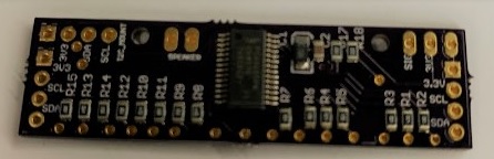
Now that we have gathered our tools, we then placed our PCB in a secure position to apply our stencil and spread the solder paste evenly with the card provided by Oshpark. Since we have components on both the top and bottom layer of the PCB, we decided to start with the bottom because it consists of more complicated components such as the PWM IC shown in Figure 1.
[/av_textblock]
[av_hr class=’invisible’ height=’20’ shadow=’no-shadow’ position=’center’ custom_border=’av-border-thin’ custom_width=’50px’ custom_border_color=” custom_margin_top=’30px’ custom_margin_bottom=’30px’ icon_select=’yes’ custom_icon_color=” icon=’ue808′ font=’entypo-fontello’]
[av_textblock size=” font_color=” color=”]
After spreading the bottom layer with solder paste, we gently place the components to its rightful location with the use of the clamp to hold the PCB secure and still and the tweezer to hold the components.
[/av_textblock]
[av_hr class=’invisible’ height=’20’ shadow=’no-shadow’ position=’center’ custom_border=’av-border-thin’ custom_width=’50px’ custom_border_color=” custom_margin_top=’30px’ custom_margin_bottom=’30px’ icon_select=’yes’ custom_icon_color=” icon=’ue808′ font=’entypo-fontello’]
[av_textblock size=” font_color=” color=”]
In reference to the SMD Soldering tutorial posted in the Technical Training folder on the EE 400D website, we preheated the oven to 350F for about 5 minutes and placed the PCB in for about a minute, then we increased the temperature to the max temperature of about 450F until the solder paste was visibly shining and hardening (about 2 and a half minutes).
[/av_textblock]
[av_hr class=’invisible’ height=’20’ shadow=’no-shadow’ position=’center’ custom_border=’av-border-thin’ custom_width=’50px’ custom_border_color=” custom_margin_top=’30px’ custom_margin_bottom=’30px’ icon_select=’yes’ custom_icon_color=” icon=’ue808′ font=’entypo-fontello’]
[av_textblock size=” font_color=” color=”]
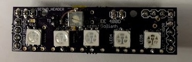
Next, we carefully removed the PCB and waited for it to cool down to room temperature before handling the top layer shown in Figure 2.
[/av_textblock]
[av_hr class=’invisible’ height=’20’ shadow=’no-shadow’ position=’center’ custom_border=’av-border-thin’ custom_width=’50px’ custom_border_color=” custom_margin_top=’30px’ custom_margin_bottom=’30px’ icon_select=’yes’ custom_icon_color=” icon=’ue808′ font=’entypo-fontello’]
[av_textblock size=” font_color=” color=”]
For the top layer, we considered reflowing it the same way as we did the bottom layer but we came across a problem where the PCB would have to be baked twice, which may cause the bottom layer components to fall down or be shifted out of place causing tombstones. So to prevent any mishaps for the bottom layer, we decided to hand solder the top layer which was not too difficult because the top layer only consisted of 8 components. When assembling, be sure to double check the polarity of the components are placed correctly to avoid any shorts. Also, be sure to test the LEDs are functioning correctly with the use of a DMM. The only problem with hand soldering SMD components is that the results were not pretty because the components were not aligned as well as the bottom components. Last but not least, the male header pins were all that was left to solder onto the PCB.
[/av_textblock]
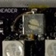
[av_heading heading=’Trim Pot’ tag=’h2′ style=” size=” subheading_active=” subheading_size=’15’ padding=’10’ color=’custom-color-heading’ custom_font=’#ff6a00′][/av_heading]
[av_textblock size=” font_color=” color=”]
Also, a problem that we came across was that the trim pot in the schematic was wired incorrectly on EACGLE CAD, which resulted in the PCB layout and manufacturing to be incorrect. However, we were able to bypass the problem by hand soldering the leads of the trim pot to the correct pads on the PCB via copper wire.
[/av_textblock]
[av_heading tag=’h2′ padding=’10’ heading=’Conclusion’ color=’custom-color-heading’ style=” custom_font=’#ff6a00′ size=” subheading_active=” subheading_size=’15’ custom_class=”][/av_heading]
[av_textblock size=” font_color=” color=”]
Overall, our PCB assembly of the bottom layer and top layer was successful. We were able to lay all of the components correctly without damaging the PCB. We learned the techniques of how to SMD solder, which we found much more useful than the time consuming of hand soldering. The use of the stencil cut our work time by half and provided a much cleaner layout. Some improvements that we can consider in the future would be to use the method of stenciling the top and bottom layer and baking it twice with the use of Kapton tape to hold down the bottom components from falling down, which was the method that the Bionic Hand used to achieve a successful PCB assembly for both the top and bottom components. Also, we will have the E&C division manager to double check our schematic to make sure all components are wired correctly to prevent errors within the board layout and manufacturing. After the PCB assembly, we can expect our E&C to test the speakers, control algorithm and its integration with the LEDs.
[/av_textblock]
[/av_one_full]