[av_one_full first min_height=” vertical_alignment=” space=” custom_margin=” margin=’0px’ padding=’0px’ border=” border_color=” radius=’0px’ background_color=” src=” background_position=’top left’ background_repeat=’no-repeat’ animation=”]
[av_textblock size=’25’ font_color=” color=”]
Goliath Fall 2016
[/av_textblock]
[av_hr class=’invisible’ height=’-50′ shadow=’no-shadow’ position=’center’ custom_border=’av-border-thin’ custom_width=’50px’ custom_border_color=” custom_margin_top=’30px’ custom_margin_bottom=’30px’ icon_select=’yes’ custom_icon_color=” icon=’ue808′ font=’entypo-fontello’]
[av_textblock size=’25’ font_color=” color=”]
PCB Schematic
[/av_textblock]
[/av_one_full]
[av_hr class=’invisible’ height=’-60′ shadow=’no-shadow’ position=’center’ custom_border=’av-border-thin’ custom_width=’50px’ custom_border_color=” custom_margin_top=’30px’ custom_margin_bottom=’30px’ icon_select=’yes’ custom_icon_color=” icon=’ue808′ font=’entypo-fontello’]
[av_textblock size=” font_color=’custom’ color=’#bfbfbf’]
By: Sou Thao (Electronics and Control)
Approved by Kristen Oduca (Project Manager)
[/av_textblock]
[av_three_fourth first min_height=” vertical_alignment=” space=” custom_margin=” margin=’0px’ padding=’0px’ border=” border_color=” radius=’0px’ background_color=” src=” background_position=’top left’ background_repeat=’no-repeat’ animation=”]
[av_textblock size=’16’ font_color=’custom’ color=’#6b6b6b’]
[/av_textblock]
[/av_three_fourth]
[av_one_full first min_height=” vertical_alignment=” space=” custom_margin=” margin=’0px’ padding=’0px’ border=” border_color=” radius=’0px’ background_color=” src=” background_position=’top left’ background_repeat=’no-repeat’ animation=”]
[av_heading tag=’h2′ padding=’10’ heading=’Introduction’ color=’custom-color-heading’ style=” custom_font=’#ff6a00′ size=” subheading_active=” subheading_size=’15’ custom_class=”][/av_heading]
[av_textblock size=” font_color=” color=”]
Requirement:
- Goliath shall have a custom PCB.
- Goliath shall use five SMD LEDs to indicate the location and distance of the Biped.
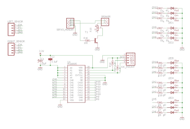
The components selected for the PCB must be laid out in the schematic. The schematic shows the interconnections between the different components so a user is able to understand the pinouts of the PCB. In our schematic, we will be using RGB LEDs to show the distance and direction of the object being tracked and we will be using a speaker for tank noises. After the schematic is finished, it will go to the manufacturer engineer who will lay out the components on the actual PCB and it will come back to electronics engineer for testing.
[/av_textblock]
[av_heading tag=’h2′ padding=’10’ heading=’EagleCAD Schematic’ color=’custom-color-heading’ style=” custom_font=’#ff6a00′ size=” subheading_active=” subheading_size=’15’ custom_class=”][/av_heading]
[av_textblock size=” font_color=” color=”]
By looking at the schematic in Figure 1, the main component driving the RGB LEDs is the PCA9685 I2C expander.
[/av_textblock]
[av_hr class=’invisible’ height=’20’ shadow=’no-shadow’ position=’center’ custom_border=’av-border-thin’ custom_width=’50px’ custom_border_color=” custom_margin_top=’30px’ custom_margin_bottom=’30px’ icon_select=’yes’ custom_icon_color=” icon=’ue808′ font=’entypo-fontello’]
[av_textblock size=” font_color=” color=”]
We used this I2C expander because we were limited in the number of pins on the 3DoT Board, especially the PWM/analog pins. Thus, the solution was to communicate through the I2C bus on the microcontroller. As a result, any user can connect multiple devices through the I2C bus, which only uses two pins for serial communication.
[/av_textblock]
[av_hr class=’invisible’ height=’20’ shadow=’no-shadow’ position=’center’ custom_border=’av-border-thin’ custom_width=’50px’ custom_border_color=” custom_margin_top=’30px’ custom_margin_bottom=’30px’ icon_select=’yes’ custom_icon_color=” icon=’ue808′ font=’entypo-fontello’]
[av_textblock size=” font_color=” color=”]
Next, we had to select the correct resistors for turning on each LED. We decided to use five SMD Common Cathode RGB LEDs from Adafruit, and by looking at the technical details of the LEDs, we can see that the turn on voltages for each LED is: Red – 1.8 to 2.1V, Green – 3 to 3.2V, and Blue – 3 to 3.2V [1]. Also we know that the voltage supply to each pin is 3.3V from the power source coming from the I2C bus. Next, from the PCA9685 datasheet the sink current on each pinout of the I2C expander is 25mA [2]. Therefore, to get the resistor value, we can use the formula shown in Figure 2:
[/av_textblock]
[av_hr class=’invisible’ height=’20’ shadow=’no-shadow’ position=’center’ custom_border=’av-border-thin’ custom_width=’50px’ custom_border_color=” custom_margin_top=’30px’ custom_margin_bottom=’30px’ icon_select=’yes’ custom_icon_color=” icon=’ue808′ font=’entypo-fontello’]
[av_textblock size=” font_color=” color=”]
Therefore, we chose our resistor values to be Red = 47Ω, Green = 10Ω, and Blue = 10Ω for each RGB LED.
[/av_textblock]
[av_hr class=’invisible’ height=’20’ shadow=’no-shadow’ position=’center’ custom_border=’av-border-thin’ custom_width=’50px’ custom_border_color=” custom_margin_top=’30px’ custom_margin_bottom=’30px’ icon_select=’yes’ custom_icon_color=” icon=’ue808′ font=’entypo-fontello’]
[av_textblock size=” font_color=” color=”]
Next up, we created mounting holes for each MaxSonar Sensor so they can connect with the I2C bus. On the datasheet for the sensor on page 4 located here, we would need pull up resistors from the 5V to the SDA and 5V to the SCL so we chose two resistor values of 2.2kΩ [3]. Moving forward, the capacitors are placed from the power source to ground and from any component pin that requires power to ground because they work as decoupling capacitors. The purpose of a decoupling capacitor is to block out the high-frequency noise from the power supply signal which can harm the ICs.
[/av_textblock]
[av_hr class=’invisible’ height=’20’ shadow=’no-shadow’ position=’center’ custom_border=’av-border-thin’ custom_width=’50px’ custom_border_color=” custom_margin_top=’30px’ custom_margin_bottom=’30px’ icon_select=’yes’ custom_icon_color=” icon=’ue808′ font=’entypo-fontello’]
[av_textblock size=” font_color=” color=”]
On the last part, we chose to use a speaker to make tank noises. In order to connect the 8 ohm 0.5W speaker to the PCB, we used a transistor that was controlled by the PWM signal from the servo header pin on the 3DoT board. We biased the transistor to work in the saturation region for the purpose of turning on and turning off the power supply to the speaker, therefore, we can create a tank noise. We also included a potentiometer in this circuit to have volume control if the speaker gets too loud.
[/av_textblock]
[av_heading tag=’h2′ padding=’10’ heading=’Testing the PCB’ color=’custom-color-heading’ style=” custom_font=’#ff6a00′ size=” subheading_active=” subheading_size=’15’ custom_class=”][/av_heading]
[av_textblock size=” font_color=” color=”]
After the manufacturing engineer designed the PCB, I was able to test the PCB with the code I had written from the previous blog post on the new control algorithm using triangulation. As expected, the LEDs displayed the correct lighting effect for direction and distance of an object detected and the sensors were able to track an object with ease. I was able to play the tank noise from the speaker, and our code ran perfectly as it did with our breadboard tests.
[/av_textblock]
[av_heading tag=’h2′ padding=’10’ heading=’Conclusion’ color=’custom-color-heading’ style=” custom_font=’#ff6a00′ size=” subheading_active=” subheading_size=’15’ custom_class=”][/av_heading]
[av_textblock size=” font_color=” color=”]
[/av_textblock]
[av_hr class=’invisible’ height=’20’ shadow=’no-shadow’ position=’center’ custom_border=’av-border-thin’ custom_width=’50px’ custom_border_color=” custom_margin_top=’30px’ custom_margin_bottom=’30px’ icon_select=’yes’ custom_icon_color=” icon=’ue808′ font=’entypo-fontello’]
[av_textblock size=” font_color=’custom’ color=’#ff6a00′]
Source Material
- https://www.adafruit.com/product/619
- https://cdn-shop.adafruit.com/datasheets/PCA9685.pdf
- http://www.maxbotix.com/documents/I2CXL-MaxSonar-EZ_Datasheet.pdf
[/av_textblock]
[/av_one_full]
