[av_textblock size=” font_color=” color=” av-medium-font-size=” av-small-font-size=” av-mini-font-size=” admin_preview_bg=”]
|
WARNING Some of the information on this page is outdated, from a time when the ArxRobot Library was still named the “Robot3DoTBoard” Library. Proceed at your own risk. |
[/av_textblock]
[av_heading tag=’h2′ padding=’10’ heading=’Programming Your Robot’ color=” style=” custom_font=” size=” subheading_active=” subheading_size=’15’ custom_class=” admin_preview_bg=” av-desktop-hide=” av-medium-hide=” av-small-hide=” av-mini-hide=” av-medium-font-size-title=” av-small-font-size-title=” av-mini-font-size-title=” av-medium-font-size=” av-small-font-size=” av-mini-font-size=”][/av_heading]
[av_textblock size=” font_color=” color=” av-medium-font-size=” av-small-font-size=” av-mini-font-size=” admin_preview_bg=”]
[/av_textblock]
[av_textblock size=” font_color=” color=” av-medium-font-size=” av-small-font-size=” av-mini-font-size=” admin_preview_bg=”]
This chapters looks at 3DoT programming from a developer’s perspective. Specifically, this material is intended for developers interested in extending the capabilities of the 3DoT Library. For example how to implement a Mars rover with 6 DC motors in place of 2 DC motors assumed by the software. Before we begin you may want to review Arxterra’s three operating modes as described in “Arxterra Operating Modes.”
[/av_textblock]
[av_heading tag=’h3′ padding=’10’ heading=’How to Override the Built in Move Command’ color=” style=” custom_font=” size=” subheading_active=” subheading_size=’15’ custom_class=” admin_preview_bg=” av-desktop-hide=” av-medium-hide=” av-small-hide=” av-mini-hide=” av-medium-font-size-title=” av-small-font-size-title=” av-mini-font-size-title=” av-medium-font-size=” av-small-font-size=” av-mini-font-size=”][/av_heading]
[av_textblock size=” font_color=” color=” av-medium-font-size=” av-small-font-size=” av-mini-font-size=” admin_preview_bg=”]
| This example can be easily extended to allow the control of six-wheel rovers, like our mini-sojourner. |
The built-in MOVE command as the name implies, is used when you want to move your robot. This command assumes a two wheel-caster or track robot. If you are building a four wheel car where the front wheels are turned with a servo or a six (6) rover, like our mini-sojourner Mars rover, you will need to override this command.
Step 1: If you have not done so already download the code for Robot_3DoT_TeleComm (see Section “01 – 5: Sample Scripts”), rename it Robot_3Dot_Blink, and open it in the Arduino IDE. ![]()
The “MOVE” command is defined as command ID 0x01 in the Configure.h file.
In the Robot_3DoT_Telecom example, this command is overridden and linked to the “moveHandler” subroutine located within the main file Robot_3Dot_Telecomm by the C callback statement:
![]()
![]()
A placeholder “moveHandler” subroutine is included with the example script.
[/av_textblock]
[av_image src=’https://www.arxterra.com/wp-content/uploads/2018/05/arduino_91.png’ attachment=’140088′ attachment_size=’full’ align=’center’ styling=” hover=” link=’lightbox’ target=” caption=” font_size=” appearance=” overlay_opacity=’0.4′ overlay_color=’#000000′ overlay_text_color=’#ffffff’ animation=’no-animation’ admin_preview_bg=”][/av_image]
[av_textblock size=” font_color=” color=” av-medium-font-size=” av-small-font-size=” av-mini-font-size=” admin_preview_bg=”]
|
WARNING This and other example handlers include Serial write instructions which can be helpful during testing. These instructions should be deleted or disabled with a block comment (/* */) after testing is completed. Failure to do so will drastically slow the MCU performance and may result in loss-of-signal and other unexpected problems. |
Step 2: For this example, I want to maintain the functionality of the built-in move instruction. To accomplish this, two motor classes need to be created. Add these two lines of code after defining the “BLINK” and “SERVO” command IDs. These will correspond to Motor A and Motor B on the 3DoT board. To better understand why these motor classes are generated, review the Motor.h and Motor.cpp files found in the 3DoT library.
[/av_textblock]
[av_image src=’https://www.arxterra.com/wp-content/uploads/2018/05/arduino_92.png’ attachment=’140089′ attachment_size=’full’ align=’center’ styling=” hover=” link=” target=” caption=” font_size=” appearance=” overlay_opacity=’0.4′ overlay_color=’#000000′ overlay_text_color=’#ffffff’ animation=’no-animation’ admin_preview_bg=”][/av_image]
[av_textblock size=” font_color=” color=” av-medium-font-size=” av-small-font-size=” av-mini-font-size=” admin_preview_bg=”]
Step 3: Next, each motor will need to be initialized to their respective driver IC pins on the microcontroller. Each motor will use three pins on the TB6612FNG for control: two for direction control and one for speed control. Conveniently, these pins are already defined in the Configure.h file in the 3Dot library. To initialize these pins for control of these motors, add the following lines of code in “setup()”of the Robot_3Dot_TeleComm file:
[/av_textblock]
[av_image src=’https://www.arxterra.com/wp-content/uploads/2018/05/arduino_93.png’ attachment=’140090′ attachment_size=’full’ align=’center’ styling=” hover=” link=” target=” caption=” font_size=” appearance=” overlay_opacity=’0.4′ overlay_color=’#000000′ overlay_text_color=’#ffffff’ animation=’no-animation’ admin_preview_bg=”][/av_image]
[av_textblock size=” font_color=” color=” av-medium-font-size=” av-small-font-size=” av-mini-font-size=” admin_preview_bg=”]
Step 4: The “MOVE” command can now be programmed. Write the following code in the “moveHandler.”
[/av_textblock]
[av_image src=’https://www.arxterra.com/wp-content/uploads/2018/05/arduino_94.png’ attachment=’140091′ attachment_size=’full’ align=’center’ styling=” hover=” link=” target=” caption=” font_size=” appearance=” overlay_opacity=’0.4′ overlay_color=’#000000′ overlay_text_color=’#ffffff’ animation=’no-animation’ admin_preview_bg=”][/av_image]
[av_textblock size=” font_color=” color=” av-medium-font-size=” av-small-font-size=” av-mini-font-size=” admin_preview_bg=”]
Step 5: Finally, our new move handler can be tested using the ArxRobot application or using CoolTerm. Turn off the 3DoT board and connect the motors as shown in Figure 15.1.
[/av_textblock]
[av_image src=’https://www.arxterra.com/wp-content/uploads/2018/05/arduino_95-1030×513.png’ attachment=’140092′ attachment_size=’large’ align=’center’ styling=” hover=” link=” target=” caption=” font_size=” appearance=” overlay_opacity=’0.4′ overlay_color=’#000000′ overlay_text_color=’#ffffff’ animation=’no-animation’ admin_preview_bg=”][/av_image]
[av_textblock size=” font_color=” color=” av-medium-font-size=” av-small-font-size=” av-mini-font-size=” admin_preview_bg=”]
Figure 15.1: Motor connection location on the 3DoT board.
[/av_textblock]
[av_textblock size=” font_color=” color=” av-medium-font-size=” av-small-font-size=” av-mini-font-size=” admin_preview_bg=”]
Step 6: Turn on the 3DoT board, upload the newly created code, open CoolTerm, connect the board, and open the “Send String” window. Ok, that may be more like 5 steps.
Step 7: Input the command string shown below. Keep in mind, the order of the packet ID, packet length, command ID, parameters, and LRC byte is important. In this command string moving from left to right: A5 represents the packet ID, 05 represents the packet length (command ID + number of parameters), 01 represents the MOVE command ID, 01 represents the forward direction of motor A, 80 represents motor A operating at half speed (0x80 is 128 in decimal which is half of 255, the maximum value for PWM), 01 represents the forward direction of motor B, 80 represents motor B operating at half speed, and A1 represents the LRC byte. Send the command packet string and verify that both motors A and B are spinning forward. If the motors are not spinning forward, there could be a possible polarity issue. Simply swap the wiring connection in order to make the motor spin in reverse.
[/av_textblock]
[av_image src=’https://www.arxterra.com/wp-content/uploads/2018/05/arduino_96.png’ attachment=’140093′ attachment_size=’full’ align=’center’ styling=” hover=” link=’lightbox’ target=” caption=” font_size=” appearance=” overlay_opacity=’0.4′ overlay_color=’#000000′ overlay_text_color=’#ffffff’ animation=’no-animation’ admin_preview_bg=”][/av_image]
[av_textblock size=” font_color=” color=” av-medium-font-size=” av-small-font-size=” av-mini-font-size=” admin_preview_bg=”]
Figure 15.2: Send Move command packet from CoolTerm.
[/av_textblock]
[av_textblock size=” font_color=” color=” av-medium-font-size=” av-small-font-size=” av-mini-font-size=” admin_preview_bg=”]
From experience, when using the “MOVE” command, it may be easier to set the speed to a fixed value since the direction pad on the Arxterra control panel (which uses the “MOVE” command) only controls the direction of the motors, not the speed. If the robot operates at a fixed speed, fixed PWM values can be put in the code. For example:
This would be more practical when implementing the “MOVE” command on Arxterra. When testing the code in CoolTerm, remove the hex byte for parameter ‘3’ since it is unused, while the hex byte for parameter ‘1’ does not matter. Nevertheless, it is important to keep the direction as parameters ‘0’ and ‘2’ since this is what is used for the direction pad on Arxterra.
Furthermore, now is a good time to explain that while commands for each motor to brake can be created manually using 0x03 as the direction hex byte, the Motor.cpp file in the 3DoT library defines a brake function. The following code will stop the motors:
[/av_textblock]
[av_image src=’https://www.arxterra.com/wp-content/uploads/2018/05/arduino_97.png’ attachment=’140094′ attachment_size=’full’ align=’left’ styling=” hover=” link=” target=” caption=” font_size=” appearance=” overlay_opacity=’0.4′ overlay_color=’#000000′ overlay_text_color=’#ffffff’ animation=’no-animation’ admin_preview_bg=”][/av_image]
[av_textblock size=” font_color=” color=” av-medium-font-size=” av-small-font-size=” av-mini-font-size=” admin_preview_bg=”]
Try creating a command to turn motorA on for 5 seconds using “motorA.go()” in conjunction with “delay()” and “motorA.brake”. Repeat the process for motorB.
[/av_textblock]
[av_button label=’Custom command program Guide – Example’ link=’manually,https://www.arxterra.com/goliath-fall-2017-app-directed-rc-record-and-playback/’ link_target=” size=’large’ position=’center’ icon_select=’yes’ icon=’ue8c9′ font=’entypo-fontello’ color=’theme-color’ custom_bg=’#444444′ custom_font=’#ffffff’ admin_preview_bg=”]
[av_heading tag=’h4′ padding=’10’ heading=’How to Program a Rover’ color=” style=” custom_font=” size=” subheading_active=” subheading_size=’15’ custom_class=” admin_preview_bg=” av-desktop-hide=” av-medium-hide=” av-small-hide=” av-mini-hide=” av-medium-font-size-title=” av-small-font-size-title=” av-mini-font-size-title=” av-medium-font-size=” av-small-font-size=” av-mini-font-size=”][/av_heading]
[av_textblock size=” font_color=” color=” av-medium-font-size=” av-small-font-size=” av-mini-font-size=” admin_preview_bg=”]
To implement a rover you would need to add a 3DoT shield with two additional motor control chips – 6 motors total. For this class of robot, you may want to write a software slip differential drive program. Communications from the 3DoT board to the shield is implemented as an I2C interface. Software communications for this serial interface protocol is implemented by the Arduino using the “wire” library.
[/av_textblock]
[av_heading tag=’h3′ padding=’10’ heading=’How the 3DoT Battery Level Circuit Works’ color=” style=” custom_font=” size=” subheading_active=” subheading_size=’15’ custom_class=” admin_preview_bg=” av-desktop-hide=” av-medium-hide=” av-small-hide=” av-mini-hide=” av-medium-font-size-title=” av-small-font-size-title=” av-mini-font-size-title=” av-medium-font-size=” av-small-font-size=” av-mini-font-size=”][/av_heading]
[av_textblock size=” font_color=” color=” av-medium-font-size=” av-small-font-size=” av-mini-font-size=” admin_preview_bg=”]
In the previous sections, we have looked at adding custom command handlers. In this and the next section, we look at how to implement telemetry channels. This example adds the BATTERY_ID telemetry channel to an Arduino Uno. This channel is hardwired into the 3DoT board and when the 3DoT board is connected to Arxterra, this data stream is automatically sent to the ArxRobot application. Consequently, to show how the channel works we will need to use an Arduino Uno in place of the 3DoT board.
In the Configure.h file, the microcontroller is programmed to read the battery level from pin A5 as shown below:
[/av_textblock]
[av_image src=’https://www.arxterra.com/wp-content/uploads/2018/05/arduino_109.png’ attachment=’140106′ attachment_size=’full’ align=’left’ styling=” hover=” link=” target=” caption=” font_size=” appearance=” overlay_opacity=’0.4′ overlay_color=’#000000′ overlay_text_color=’#ffffff’ animation=’no-animation’ admin_preview_bg=”][/av_image]
[av_textblock size=” font_color=” color=” av-medium-font-size=” av-small-font-size=” av-mini-font-size=” admin_preview_bg=”]
Step 1: Connect a potentiometer to the Arduino Uno with the two outer pins connected to 5V and GND, while the middle pin is connected to A5 as shown in Figure 15.4. In this circuit, the potentiometer is acting as a voltage divider to divide the 5V between the two variable resistors embedded in the potentiometer. As the potentiometer is turned to the right, the voltage output will increase and decrease as it is turned to the left.
[/av_textblock]
[av_image src=’https://www.arxterra.com/wp-content/uploads/2018/05/arduino_110.png’ attachment=’140107′ attachment_size=’full’ align=’center’ styling=” hover=” link=” target=” caption=” font_size=” appearance=” overlay_opacity=’0.4′ overlay_color=’#000000′ overlay_text_color=’#ffffff’ animation=’no-animation’ admin_preview_bg=”][/av_image]
[av_textblock size=” font_color=” color=” av-medium-font-size=” av-small-font-size=” av-mini-font-size=” admin_preview_bg=”]
Figure 15.4: Fritzing diagram of potentiometer connected to the Arduino Uno.
[/av_textblock]
[av_textblock size=” font_color=” color=” av-medium-font-size=” av-small-font-size=” av-mini-font-size=” admin_preview_bg=”]
Step 2: Upload “Robot_3Dot_TeleComm” to the Arduino Uno and open CoolTerm. Select the “View Hex” option. As soon as the board is connected, two telemetry strings should appear. The first string is for the battery level and the second is for the motor current.
Step 3: Select “Clear Data” to clear existing data.
Step 4: The potentiometer should be dialed to the left and slowly turned to the right. The battery level telemetry will continually update as the simulated battery level changes (potentiometer). The battery levels are shown here.
[/av_textblock]
[av_image src=’https://www.arxterra.com/wp-content/uploads/2018/05/arduino_111-1030×85.png’ attachment=’140108′ attachment_size=’large’ align=’center’ styling=” hover=” link=” target=” caption=” font_size=” appearance=” overlay_opacity=’0.4′ overlay_color=’#000000′ overlay_text_color=’#ffffff’ animation=’no-animation’ admin_preview_bg=”][/av_image]
[av_textblock size=” font_color=” color=” av-medium-font-size=” av-small-font-size=” av-mini-font-size=” admin_preview_bg=”]
Figure 15.5: Output from CoolTerm of potentiometer connected to the Arduino Uno.
[/av_textblock]
[av_textblock size=” font_color=” color=” av-medium-font-size=” av-small-font-size=” av-mini-font-size=” admin_preview_bg=”]
The first byte, “CA”, is the packet ID, the second byte, “03”, is the packet length, the third byte, “06”, is the telemetry ID, the fourth byte, “00”, is an empty parameter, the fifth byte, “07”, is the parameter desired which shows the battery level in hex. The last byte, “C8”, is the LRC byte.
As shown above, when the potentiometer is turned from left to right, the following parameter values were achieved: {0x07, 0x14, 0x1A, 0x3D, 0x54, 0x59, 0x5E, and 0x63}. Translating these hex values to decimal: {7, 20, 26, 61, 84, 89, 94, and 99}. These values represent the battery level percentage. So the “battery” started at 7% and “charged” to 99%.
[/av_textblock]
[av_heading tag=’h2′ padding=’10’ heading=’Custom Telemetry’ color=” style=” custom_font=” size=” subheading_active=” subheading_size=’15’ custom_class=” admin_preview_bg=” av-desktop-hide=” av-medium-hide=” av-small-hide=” av-mini-hide=” av-medium-font-size-title=” av-small-font-size-title=” av-mini-font-size-title=” av-medium-font-size=” av-small-font-size=” av-mini-font-size=”][/av_heading]
[av_textblock size=” font_color=” color=” av-medium-font-size=” av-small-font-size=” av-mini-font-size=” admin_preview_bg=”]
In this section, we will go over the custom telemetry example provided in Robot_3Dot_TeleComm example script.
Step 1: The first step is to instantiate (“build”) a packet object named motor PWM and initialize its properties. MOTOR2_CURRENT_ID is a pre-defined telemetry channel equal to 0x02 as defined in the Configure.h text file.
[/av_textblock]
[av_image src=’https://www.arxterra.com/wp-content/uploads/2018/05/arduino_112.png’ attachment=’140109′ attachment_size=’full’ align=’left’ styling=” hover=” link=” target=” caption=” font_size=” appearance=” overlay_opacity=’0.4′ overlay_color=’#000000′ overlay_text_color=’#ffffff’ animation=’no-animation’ admin_preview_bg=”][/av_image]
[av_textblock size=” font_color=” color=” av-medium-font-size=” av-small-font-size=” av-mini-font-size=” admin_preview_bg=”]
Step 2 (optional): Along with setting the telemetry ID property, the motorPWM constructor initializes both the “accuracy” and “samplePeriod” properties to their default values of 2 DN (digital number) and 1000 ms (1 second) respectively. These values should work for most robot application and no further action is needed. In this “optional” step, these default values are changed to 1 DN and 500 ms (0.5 seconds). Again, do not override the program’s default values unless required by your project.
[/av_textblock]
[av_image src=’https://www.arxterra.com/wp-content/uploads/2018/05/arduino_113.png’ attachment=’140110′ attachment_size=’full’ align=’left’ styling=” hover=” link=” target=” caption=” font_size=” appearance=” overlay_opacity=’0.4′ overlay_color=’#000000′ overlay_text_color=’#ffffff’ animation=’no-animation’ admin_preview_bg=”][/av_image]
[av_textblock size=” font_color=” color=” av-medium-font-size=” av-small-font-size=” av-mini-font-size=” admin_preview_bg=”]
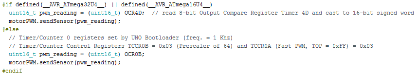
Step 3: Next, within “loop()” code segment, the sensor data is read and if the sampling criteria are met (change in DN or sample period) then a telemetry packet is sent. In the example below the “#if” conditional-compilation directive (also known as a preprocessor directive) is chosen if a board with an ATmega32u4 (e.g., 3Dot, Lilypad USB, and Leonardo) is being used and the “#else” directive is chosen if the Uno is being used. Below demonstrates using the Uno.
[/av_textblock]
[av_image src=’https://www.arxterra.com/wp-content/uploads/2018/05/arduino_114.png’ attachment=’140111′ attachment_size=’full’ align=’center’ styling=” hover=” link=” target=” caption=” font_size=” appearance=” overlay_opacity=’0.4′ overlay_color=’#000000′ overlay_text_color=’#ffffff’ animation=’no-animation’ admin_preview_bg=”][/av_image]
[av_textblock size=” font_color=” color=” av-medium-font-size=” av-small-font-size=” av-mini-font-size=” admin_preview_bg=”]
Figure 15.6: Loop code segment from Robot_3Dot_TeleComm.
[/av_textblock]
[av_heading tag=’h3′ padding=’10’ heading=’Using the UNO’ color=” style=” custom_font=” size=” subheading_active=” subheading_size=’15’ custom_class=” admin_preview_bg=” av-desktop-hide=” av-medium-hide=” av-small-hide=” av-mini-hide=” av-medium-font-size-title=” av-small-font-size-title=” av-mini-font-size-title=” av-medium-font-size=” av-small-font-size=” av-mini-font-size=”][/av_heading]
[av_textblock size=” font_color=” color=” av-medium-font-size=” av-small-font-size=” av-mini-font-size=” admin_preview_bg=”]
Step 4: Rather than sending a command to the motors to read the telemetry, it may be easier to manually code them for the time being. Just do not forget to remove this code later. If the Uno is being used, put code to analogWrite to pin 5.
[/av_textblock]
[av_image src=’https://www.arxterra.com/wp-content/uploads/2018/05/arduino_115.png’ attachment=’140112′ attachment_size=’full’ align=’left’ styling=” hover=” link=” target=” caption=” font_size=” appearance=” overlay_opacity=’0.4′ overlay_color=’#000000′ overlay_text_color=’#ffffff’ animation=’no-animation’ admin_preview_bg=”][/av_image]
[av_textblock size=” font_color=” color=” av-medium-font-size=” av-small-font-size=” av-mini-font-size=” admin_preview_bg=”]
Without getting into the details of Pulse Width Modulation (PWM), the Arduino implements this instruction by setting the Timer 0 Output Compare Register B (0CR0B) equal to 200 (Hexadecimal C8). When Timer 0 counts up to 200 the output of Arduino digital pin 5 is cleared. Please reference Figure 15.7 for all the pins on the Uno and to which timer output pin they are mapped.
[/av_textblock]
[av_image src=’https://www.arxterra.com/wp-content/uploads/2018/05/arduino_116.png’ attachment=’140113′ attachment_size=’full’ align=’center’ styling=” hover=” link=’lightbox’ target=” caption=” font_size=” appearance=” overlay_opacity=’0.4′ overlay_color=’#000000′ overlay_text_color=’#ffffff’ animation=’no-animation’ admin_preview_bg=”][/av_image]
[av_textblock size=” font_color=” color=” av-medium-font-size=” av-small-font-size=” av-mini-font-size=” admin_preview_bg=”]
Figure 15.7: Arduino UNO timers and corresponding output pins.
[/av_textblock]
[av_textblock size=” font_color=” color=” av-medium-font-size=” av-small-font-size=” av-mini-font-size=” admin_preview_bg=”]
The code within the “#else” block reads Timer 0 Output Compare Register B (0CR0B) and sets variable “pwm_reading” equal to this value. This register value is then sent as an argument to the “sendSensor()” method. Ultimately, the is packetized and set to via USB to the PC.
Step 5: To view this packet, open CoolTerm, connect the board, and View Hex. A similar reading as shown in Figure 15.8 should appear.
[/av_textblock]
[av_image src=’https://www.arxterra.com/wp-content/uploads/2018/05/arduino_117.png’ attachment=’140114′ attachment_size=’full’ align=’left’ styling=” hover=” link=” target=” caption=” font_size=” appearance=” overlay_opacity=’0.4′ overlay_color=’#000000′ overlay_text_color=’#ffffff’ animation=’no-animation’ admin_preview_bg=”][/av_image]
[av_textblock size=” font_color=” color=” av-medium-font-size=” av-small-font-size=” av-mini-font-size=” admin_preview_bg=”]
Figure 15.8: Telemetry sequence showing value of the 0CR0B register.
[/av_textblock]
[av_textblock size=” font_color=” color=” av-medium-font-size=” av-small-font-size=” av-mini-font-size=” admin_preview_bg=”]
In Figure 15.8, the first telemetry sequence is the battery telemetry, and can be disregarded for now. The second telemetry sequence, which is boxed in red, is the 0CR0B value in hex (0x00C8). In decimal this is 200, which not surprisingly, is the value sent as the second argument in the analogWrite instruction. Now, this telemetry is meant to be implemented to read the current of a motor, while right now, it is only reading a PWM value that was written.
[/av_textblock]
[av_hr class=’short’ height=’50’ shadow=’no-shadow’ position=’center’ custom_border=’av-border-thin’ custom_width=’50px’ custom_border_color=” custom_margin_top=’30px’ custom_margin_bottom=’30px’ icon_select=’yes’ custom_icon_color=” icon=’ue808′ font=’entypo-fontello’ admin_preview_bg=”]
[av_button label=’Continue to Tutorial on Fast Pulse Width Modulation’ link=’manually,https://www.arxterra.com/tutorial-on-fast-pulse-width-modulation/’ link_target=” size=’large’ position=’center’ icon_select=’yes-right-icon’ icon=’ue87d’ font=’entypo-fontello’ color=’theme-color’ custom_bg=’#444444′ custom_font=’#ffffff’ admin_preview_bg=”]