Written by Railan Oviedo (Manufacturing)
Table of Contents
Introduction
For this semester’s version of Pete-Bot, the rapid prototyping process involved the verification of being able to fit the motors and the 3DoT board inside a single 3D-printed chassis piece. Furthermore, after confirming that the base design was suitable for fitting the motors and the 3DoT board, the model itself would be altered in order to reduce print time. For information on the print time for each version, see the Print Time post.
Printed Version 1
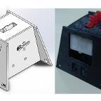
Shown are side-by-side views of the first version (Model vs. Printed Model). The chassis was printed through the use of Northrop Grumman’s 3D-printer thanks to the connections of a fellow student.


Testing 3DoT Board Placement
The mechanism for placing the board in this version is the flap in the back side, which can be pulled to allow for the board to be pushed into the chassis. This was tested and confirmed to work; however, the flimsy nature of the flap caused it to break off of the model, which is why it cannot be seen in the pictures. As such, it was decided that a new mechanism will have to implemented for follow-up versions.
Testing Motor Placement
After attempting to fit the motors inside the chassis, it was found that they could not directly be placed inside with the current design. The 3D-model pictures were altered after printing the chassis, so they show the possible solution to allowing the motors to be placed inside.
Printed Version 2
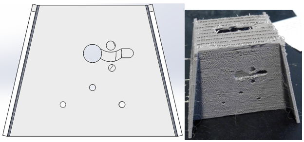
The second version’s design is as follows. This was printed at the same Northrop Grumman source, but the printer experienced a malfunction mid-print so the chassis came out in a much less stable state than originally anticipated. All versions after this were printed through Ridwan.


Updates from Version 1
- Pathway on the side has been made to allow the motors to be inserted into the chassis
- Flap design has been altered so that there are now two small flaps that bend in the same direction of the printed layers
- Holes were added to the bottom part of the front in order to allow the push-pins to have a place to be inserted. These push-pins will secure the paper shell to the chassis
- Removed the two tiny holes in the front, as they were deemed to serve no purpose
Testing 3DoT Board Placement
This version still incorporates flaps of a sort, but the orientation has been switched. Instead, they bend towards the same direction of the printed layers, thus allowing for a stronger resistance to breaking. The board was once again confirmed to fit inside, but the flimsiness of the flaps were still notable, so further changes were made for future versions.
Testing Motor Placement
Despite the deformation of the design during the printing process, it was confirmed that adding the pathway between the holes allowed for both motors to be successfully inserted at the same time. From this version onwards, this part of the design remains the same since it properly performs its purpose and simultaneously leads to a lower print time.
Printed Version 3
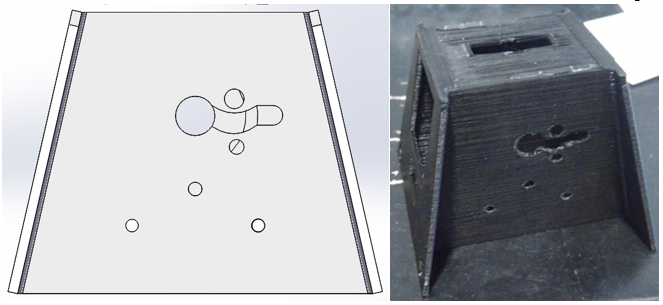
As follows is the third design.


Updates from Version 2
- Flaps were completely removed, in favor of making one section of the bottom somewhat separated from the rest of the chassis
Testing 3DoT Board Placement
After replacing the flaps with a small section of the chassis that can be pulled outward, it was found that this design is also sufficient in getting the 3Dot board placed inside. Furthermore, since no part of the chassis acts as a flap, the overall structure and security of the board in the chassis has increased. From all versions after this, the design for the 3DoT Board Placement will remain relatively the same.
Printed Version 4
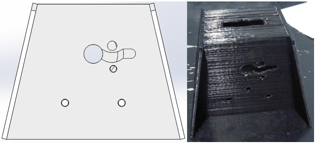
The fourth design is as follows:


Updates from Version 3
- Structures have been put in place on the inside of the chassis to allow for stable screw placement for the gear system
- Holes on the side of the chassis have been repositioned for gear testing
Testing 3DoT Board Placement
During this iteration of the chassis, it was discovered that the micro-USB port and the power switch attached to a fully aseembled 3DoT board were unable to fit within the previous design. As such, larger holes were placed in the front to allow these parts of the board to fit inside. However, after testing, it was found that these changes were not enough, so revisions to the front will be made for future versions.
Printed Version 5
This version was the most recent upon the creation of this post, so it is photographed with the motors and unassembled 3DoT board in place.


Updates from Version 4
- Because push-pins will only be inserted on the bak of the chassis, the front circular holes have been replaced with rectangular ones in order to accomodate a wooden platform that the castor wheel and color shield will attach to
- The holes on the front have been expanded to allow for both the micro-USB port and the power switch to be inserted without hindrance
Testing 3DoT Board Placement
Despite the changes made to the front, it was found that the holes need to be even wider so that the fully assembled 3DoT can be placed inside. Besides this, no other design changes seem to be necessary.
Printed Version 6
This version is the latest as of December 12. It is pictured here with the planetary gear system, the wooden platform, and the castor wheel in place.


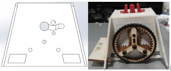
Updates from Version 5
- After discovering that push pins are actually placed on the front, holes were put back in place to match their positioning with the paper shell’s holes for the push pins
- The positioning for the micro-USB and power switch has been moved to the back of the chassis. Furthermore, the back has been opened up to allow for access to both without having to remove the board from the chassis
- Rectangular openings have been made on the side of the chassis to make space for the SAMB11 board’s power switch
- The round holes on the side of the chassis have been adjusted in such a way that the planetary gear system now functions perfectly
- The front of the chassis has had holes put into it to accommodate a possible motion sensor. However, implementation of this sensor would result in having to cut out part of the paper shell
- The front of the chassis has had its bottom partially removed to account for the front IR shield that will connect to the 3DoT. Slots have also been placed on the front of the chassis to allow the shield to snap into place
Testing 3DoT Board Placement
With this design, the fully assembled 3DoT was finally confirmed to fit inside. Attaching the IR shield to the board further increases its stability within the chassis due to the slots added to the front.
Wooden Platform
The design for the wooden platform began after it was confirmed that the fully assembled 3DoT with the shield could be placed in the chassis. The Solid Works image of the model is as follows:

After laser cutting the model out of wood, the assembled piece appears as:
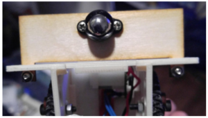
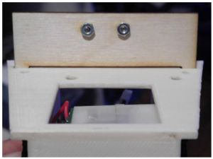
As shown in the pictures, both the castor wheel and wooden platform were confirmed to fit on the chassis. The platform is secured into its place with nuts and screws, and has the ability to slightly wiggle vertically in order to allow for better shock absorption for the castor wheel.
Summary Table

