[av_one_full first min_height=” vertical_alignment=” space=” custom_margin=” margin=’0px’ padding=’0px’ border=” border_color=” radius=’0px’ background_color=” src=” background_position=’top left’ background_repeat=’no-repeat’ animation=”]
[av_textblock size=’35’ font_color=” color=” av-medium-font-size=” av-small-font-size=” av-mini-font-size=” admin_preview_bg=”]
ModWheels Generation #3 Spring 2020
[/av_textblock]
[av_hr class=’default’ height=’50’ shadow=’no-shadow’ position=’center’ custom_border=’av-border-thin’ custom_width=’50px’ custom_border_color=” custom_margin_top=’30px’ custom_margin_bottom=’30px’ icon_select=’yes’ custom_icon_color=” icon=’ue808′ font=’entypo-fontello’ admin_preview_bg=”]
[av_textblock size=’30’ font_color=’custom’ color=” av-medium-font-size=” av-small-font-size=” av-mini-font-size=” admin_preview_bg=”]
Research & Trade Off Studies : Super-Capacitor & Metal Gear Motors
[/av_textblock]
[av_textblock size=” font_color=’custom’ color=’#bfbfbf’ av-medium-font-size=” av-small-font-size=” av-mini-font-size=” admin_preview_bg=”]
Author: Jose Avila (PM)
[/av_textblock]
[av_hr class=’short’ height=’50’ shadow=’no-shadow’ position=’left’ custom_border=’av-border-thin’ custom_width=’50px’ custom_border_color=” custom_margin_top=’30px’ custom_margin_bottom=’30px’ icon_select=’yes’ custom_icon_color=” icon=’ue808′ font=’entypo-fontello’ admin_preview_bg=”]
[av_textblock size=” font_color=” color=”]
[/av_textblock]
[av_heading tag=’h1′ padding=’10’ heading=’Introduction ‘ color=” style=” custom_font=” size=” subheading_active=” subheading_size=’15’ custom_class=” admin_preview_bg=” av-desktop-hide=” av-medium-hide=” av-small-hide=” av-mini-hide=” av-medium-font-size-title=” av-small-font-size-title=” av-mini-font-size-title=” av-medium-font-size=” av-small-font-size=” av-mini-font-size=”][/av_heading]
[av_textblock size=” font_color=” color=” av-medium-font-size=” av-small-font-size=” av-mini-font-size=” admin_preview_bg=”]
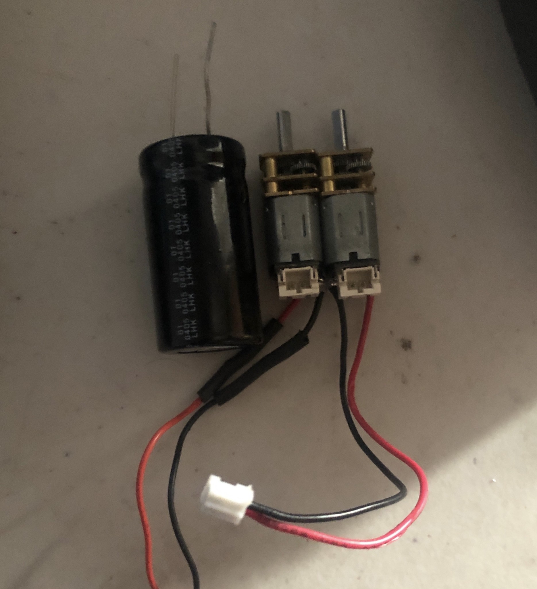
For the Spring 2020 ModWheels toy-car, the perfect combination of speed and torque was necessary for the robot to accomplish the desired stunts. Specifically, for the vehicle to successfully traverse the obstacles on the final demo track, a calculated minimum speed with the boost applied would have to be attainable. Since the 3DoT board powers the motors at 5V, using an additional power source could allow the motors to run at a more traditional 6-12V range. In our design, a fully charged supercapacitor located on the boost shield would be able to dump its current directly into the motor driver. If implemented correctly, for a short moment of time, the motors would be running at a higher voltage and therefore should result in an increased vehicle speed due to a higher motor RPM. With that being said, a higher RPM does not directly translate to a faster vehicle if the motor’s torque is too low to move the weight of the toy-car. Worst case scenario, if the motors are being run at a very high RPM but also with minimal torque, the ModWheels toy-car may be unable to move. Therefore it is crucial to integrate the appropriate supercapacitor and metal gear motors within the final product to reach speeds granting a mission success.
[/av_textblock]
[av_heading tag=’h1′ padding=’10’ heading=’Super-Capacitor’ color=” style=” custom_font=” size=” subheading_active=” subheading_size=’15’ custom_class=” admin_preview_bg=” av-desktop-hide=” av-medium-hide=” av-small-hide=” av-mini-hide=” av-medium-font-size-title=” av-small-font-size-title=” av-mini-font-size-title=” av-medium-font-size=” av-small-font-size=” av-mini-font-size=”]
Stuff we will put here woohoo…
[/av_heading]
[av_heading tag=’h2′ padding=’10’ heading=’Super-Cap Introduction’ color=” style=’blockquote modern-quote’ custom_font=” size=” subheading_active=” subheading_size=’15’ custom_class=” admin_preview_bg=” av-desktop-hide=” av-medium-hide=” av-small-hide=” av-mini-hide=” av-medium-font-size-title=” av-small-font-size-title=” av-mini-font-size-title=” av-medium-font-size=” av-small-font-size=” av-mini-font-size=”][/av_heading]
[av_textblock size=” font_color=” color=” av-medium-font-size=” av-small-font-size=” av-mini-font-size=” admin_preview_bg=”]
Before looking at the characteristics of any capacitor, we need to understand what options are available that will be integrable with the 3DoT. Since the super-capacitor voltage and current is going through the 5V_VM line and into the motor driver, we need to know the absolute maximum ratings of the DRV8848 Dual H-Bridge Motor Drive. Luckily, since we modified the 3DoT at the beginning of the course, the H-Bridge and motors are the only components being exposed to the super-capacitor discharge. With that being said, the DRV8848 is recommended to be operated between 4 and 18V, with an absolute maximum rating of 20V.
With that knowledge, we can start looking at the motors themselves. On Pololu, most motors are meant to be operated between 6-12V. Although no absolute maximum ratings are provided, we can start formulating what voltage the super-capacitor can be rated at. Let’s assume for a short moment in time, we operate at the highest recommended voltage for the DRV8848 which is 18V. Assuming there’s a short moment where the 5V from the 3DoT and voltage from the capacitor add up and go into the DRV8848, we could use a capacitor rated at 13V and we would still not be near the absolute maximum for the H-bridge. With that being said, to avoid burning out the metal gear motors, 12V seems like the most ideal voltage for the turbo-boost shield capacitor. Sites like digikey.com will allow us to see all our options for a 12V super-capacitor and make a decision on which component should be integrated into our design.
[/av_textblock]
[av_heading tag=’h2′ padding=’10’ heading=’12 V Super-Capacitors : A Digikey Overview’ color=” style=’blockquote modern-quote’ custom_font=” size=” subheading_active=” subheading_size=’15’ custom_class=” admin_preview_bg=” av-desktop-hide=” av-medium-hide=” av-small-hide=” av-mini-hide=” av-medium-font-size-title=” av-small-font-size-title=” av-mini-font-size-title=” av-medium-font-size=” av-small-font-size=” av-mini-font-size=”][/av_heading]
[av_textblock size=” font_color=” color=” av-medium-font-size=” av-small-font-size=” av-mini-font-size=” admin_preview_bg=”]
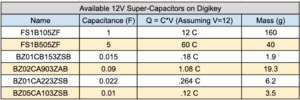
Knowing that our super-capacitor will be rated for 12V, we can filter this parameter into the Digikey website and see our options. Only 6 are available but we can dismiss the FS1B105ZF because it just simply weighs too much. Even though it has the highest charge potential, it could outweigh all the other parts even if they were added up. In addition, we can ignore the BZ05CA103ZSB & BZ01CB153ZSB because the charge is the lowest and has very similar characteristics to the BZ01CA223ZSB . With that being said, we can do some theoretical calculations on the remaining super-capacitors and see if the previously ignored parts need to be revisited. As it stands, we will be looking at theoretical charge and discharge times of the FS1B105ZF, BZ02CA903ZAB, and BZ01CA223ZSB.
All the 12V super-capacitors on Digikey with some key rated values.
[/av_textblock]
[av_heading tag=’h2′ padding=’10’ heading=’Theoretical Calculations’ color=” style=’blockquote modern-quote’ custom_font=” size=” subheading_active=” subheading_size=’15’ custom_class=” admin_preview_bg=” av-desktop-hide=” av-medium-hide=” av-small-hide=” av-mini-hide=” av-medium-font-size-title=” av-small-font-size-title=” av-mini-font-size-title=” av-medium-font-size=” av-small-font-size=” av-mini-font-size=”][/av_heading]
[av_textblock size=” font_color=” color=” av-medium-font-size=” av-small-font-size=” av-mini-font-size=” admin_preview_bg=”]
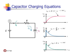
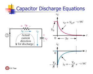
Choosing how to simulate the super-capacitor before ordering it was extremely tricky. The price of each was $20 at least and without knowing what the design was going to look like throughout the semester, calculations for capacitor charge and discharge times could be inaccurate. The good thing is that we just need the general behavior of each capacitor before purchasing one. With that being said, we simply will have each capacitor discharging into a 100 ohm resistor and be able to use the most simple charge and discharge equations equations for this simulation. We will use the equations shown in the images below.
Charging circuit and equation used for theoretical calculations using Matlab.
Discharging circuit and equation used for theoretical calculations using Matlab.
[/av_textblock]
[av_heading tag=’h2′ padding=’10’ heading=’Matlab Results ‘ color=” style=’blockquote modern-quote’ custom_font=” size=” subheading_active=” subheading_size=’15’ custom_class=” admin_preview_bg=” av-desktop-hide=” av-medium-hide=” av-small-hide=” av-mini-hide=” av-medium-font-size-title=” av-small-font-size-title=” av-mini-font-size-title=” av-medium-font-size=” av-small-font-size=” av-mini-font-size=”][/av_heading]
[av_textblock size=” font_color=” color=” av-medium-font-size=” av-small-font-size=” av-mini-font-size=” admin_preview_bg=”]
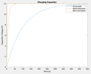
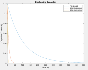
Again, after analyzing these results with a grain of salt, we notice that the FS1B105ZF has a significantly longer charge and discharge time which is expected due to its higher capacitance and therefore larger time constant. This is important to note because there is a higher chance that the current discharge time will not be instantaneous within the final design. For the other two super-capacitors, the BZ02CA903ZAB and the BZ01CA223ZSB, the discharge time was significantly shorter and could potentially pose a problem during our V1 demo and further. If the super-capacitor discharge time is extremely short, the RPM increase on the motors will hardly be noticeable. In addition, when we want to traverse a loop, we may need the boost to last a second or two instead of potentially milliseconds. This is why, for the V1 demo, we will order the FS1B105ZF because at worst case, the super-capacitor will take a longer time to charge but the RPM increase will be easier to spot on the metal gear motor. Even though it is impossible to get a perfect simulation without starting the design process in depth, having some understanding of how each capacitor will behave is important because the group needs to order one for the V1 demo.
Matlab plot of 3 charging super-capacitors to analyze charge time.
Matlab plot of 3 discharging super-capacitors to analyze discharge time.
[/av_textblock]
[av_heading tag=’h2′ padding=’10’ heading=’ FS1B105ZF Verification’ color=” style=’blockquote modern-quote’ custom_font=” size=” subheading_active=” subheading_size=’15’ custom_class=” admin_preview_bg=” av-desktop-hide=” av-medium-hide=” av-small-hide=” av-mini-hide=” av-medium-font-size-title=” av-small-font-size-title=” av-mini-font-size-title=” av-medium-font-size=” av-small-font-size=” av-mini-font-size=”][/av_heading]
[av_textblock size=” font_color=” color=” av-medium-font-size=” av-small-font-size=” av-mini-font-size=” admin_preview_bg=”]
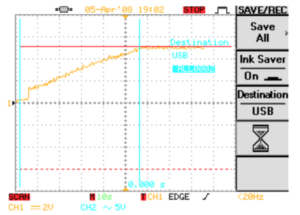
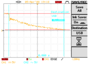
After creating a breadboarded turbo-boost prototype integrated with the FS1B105ZF, we were able to use an oscilloscope and more accurately measure the charge and discharge times of the super-capacitor when being unloaded on a metal gear motor. Fortunately, the results showed a positive sign that we could continue moving forward with this component. First of all, the charging time for the super-capacitor to reach 12V took about 50 seconds. Although this seems a little long, when it is time to demo the fully integrated product, most likely will demonstrate other aspects of the car first before showing off the turbo-boost system, therefore roughly a charging time of 1 minute for the V1 design was acceptable. As far as the discharge time, it took about 40 seconds for the capacitor to reach 0V. Although having a boost last this long may be a bit redundant, it is important to note that the capacitor voltage reaches 5V in about 8 seconds. At 5V there would be no reason to keep the capacitor powering on the motors when it could simply be utilizing the 5V from the 3DoT. Therefore, if the actual discharge time pertaining to us is 8 seconds, yet again, we can continue our turbo-boost design interactions with the FS1B105ZF as the super-capacitor.
Oscilloscope measurements of charging super-capacitor integrated with breadboarded turbo-boost system prototype.
Oscilloscope measurements of discharging super-capacitor integrated with breadboarded turbo-boost system prototype.
[/av_textblock]
[av_heading tag=’h1′ padding=’10’ heading=’Micro Metal Gear Motors’ color=” style=” custom_font=” size=” subheading_active=” subheading_size=’15’ custom_class=” admin_preview_bg=” av-desktop-hide=” av-medium-hide=” av-small-hide=” av-mini-hide=” av-medium-font-size-title=” av-small-font-size-title=” av-mini-font-size-title=” av-medium-font-size=” av-small-font-size=” av-mini-font-size=”]
Stuff we will put here woohoo…
[/av_heading]
[av_heading tag=’h2′ padding=’10’ heading=’MGM Introduction’ color=” style=’blockquote modern-quote’ custom_font=” size=” subheading_active=” subheading_size=’15’ custom_class=” admin_preview_bg=” av-desktop-hide=” av-medium-hide=” av-small-hide=” av-mini-hide=” av-medium-font-size-title=” av-small-font-size-title=” av-mini-font-size-title=” av-medium-font-size=” av-small-font-size=” av-mini-font-size=”][/av_heading]
[av_textblock size=” font_color=” color=” av-medium-font-size=” av-small-font-size=” av-mini-font-size=” admin_preview_bg=”]
After finalizing which super-capacitor was going to be implemented into our boost-shield design, we quickly had to determine which metal gear motors would be used for the V2 and final demos. As explained before, the motors needed to have a good combination of speed (RPM) and torque if ModWheels was gonna reach our goal of 5.6 FPS and traverse the loop-de-loop obstacle. Luckily, we had a set of old motors that would not only be used for the V1 demo, but be used as our initial starting point for micro metal gear motors.
[/av_textblock]
[av_heading tag=’h2′ padding=’10’ heading=’ MGM Testing & Research : Part 1′ color=” style=’blockquote modern-quote’ custom_font=” size=” subheading_active=” subheading_size=’15’ custom_class=” admin_preview_bg=” av-desktop-hide=” av-medium-hide=” av-small-hide=” av-mini-hide=” av-medium-font-size-title=” av-small-font-size-title=” av-mini-font-size-title=” av-medium-font-size=” av-small-font-size=” av-mini-font-size=”][/av_heading]
[av_heading tag=’h3′ padding=’10’ heading=’Identifying the First Set of Motors’ color=” style=’blockquote modern-quote’ custom_font=” size=” subheading_active=” subheading_size=’15’ custom_class=” admin_preview_bg=” av-desktop-hide=” av-medium-hide=” av-small-hide=” av-mini-hide=” av-medium-font-size-title=” av-small-font-size-title=” av-mini-font-size-title=” av-medium-font-size=” av-small-font-size=” av-mini-font-size=”][/av_heading]
[av_textblock size=” font_color=” color=” av-medium-font-size=” av-small-font-size=” av-mini-font-size=” admin_preview_bg=”]
Even though we had a set of motors that we could use to integrate into our V1 toy-car, we did not know what they were rated at as far as gear ratio,RPM, and voltage rating. This was crucial information to know because we needed a reference point when the time came to purchase an upgraded set of motors.
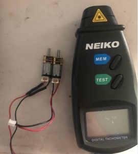
With that being said we tested the motors at 6V and 12V to try and get an estimate of the rated values. For this test, we would use a tachometer to identify RPM and a multimeter to check for the current drawn by each motor individually. In addition, a DC power source was required to test the motors at both voltages mentioned.
Digital tachometer used to measure RPM of previous ModWheels generation’s motors.
[/av_textblock]
[av_heading tag=’h3′ padding=’10’ heading=’Motor Set 1 Experimental Results’ color=” style=’blockquote modern-quote’ custom_font=” size=” subheading_active=” subheading_size=’15’ custom_class=” admin_preview_bg=” av-desktop-hide=” av-medium-hide=” av-small-hide=” av-mini-hide=” av-medium-font-size-title=” av-small-font-size-title=” av-mini-font-size-title=” av-medium-font-size=” av-small-font-size=” av-mini-font-size=”][/av_heading]
[av_textblock size=” font_color=” color=” av-medium-font-size=” av-small-font-size=” av-mini-font-size=” admin_preview_bg=”]
After testing each motor separately at 12V, motor 1 displayed a 498 RPM while motor 2 displayed 520 RPM, each with no load. In addition motor 1 was drawing 52 mA and motor 2 was drawing 54 mA. At 6V motor 1 showed a 231 RPM while motor 2 was 244 RPM. As far as current, both motors were drawing 37 mA with no load. With this information and data sheets provided on the Pololu website, we estimated that the motors had a 50:1 gear ratio.
Table of original motors data measured with digital tachometer and multimeter

[/av_textblock]
[av_heading tag=’h3′ padding=’10’ heading=’Vehicle Speed with 50:1 Gear Ratio Motors’ color=” style=’blockquote modern-quote’ custom_font=” size=” subheading_active=” subheading_size=’15’ custom_class=” admin_preview_bg=” av-desktop-hide=” av-medium-hide=” av-small-hide=” av-mini-hide=” av-medium-font-size-title=” av-small-font-size-title=” av-mini-font-size-title=” av-medium-font-size=” av-small-font-size=” av-mini-font-size=”][/av_heading]
[av_textblock size=” font_color=” color=” av-medium-font-size=” av-small-font-size=” av-mini-font-size=” admin_preview_bg=”]
After I discovered the ratings of our first set of motors and integrated our boost-shield breadboarded prototype to the vehicle itself, I wanted to see how fast ModWheels was before ordering the upgraded motors. To test this, I used a stopwatch to measure how fast ModWheels would cross a 3 foot stretch on the sidewalk. By timing this, we would be able to calculate ModWheels speed in feet per second. In addition, we tested the vehicle’s speed with and without the turbo-boost. Knowing this data, we would order new motors as we saw fit.
3 foot marked sidewalk that was used for vehicle speed experiments.

[/av_textblock]
[av_textblock size=” font_color=” color=” av-medium-font-size=” av-small-font-size=” av-mini-font-size=” admin_preview_bg=”]
Table of experimental results when testing the vehicles speed with the original motors.

[/av_textblock]
[av_heading tag=’h2′ padding=’10’ heading=’MGM Testing & Research : Part 2′ color=” style=’blockquote modern-quote’ custom_font=” size=” subheading_active=” subheading_size=’15’ custom_class=” admin_preview_bg=” av-desktop-hide=” av-medium-hide=” av-small-hide=” av-mini-hide=” av-medium-font-size-title=” av-small-font-size-title=” av-mini-font-size-title=” av-medium-font-size=” av-small-font-size=” av-mini-font-size=”][/av_heading]
[av_heading tag=’h3′ padding=’10’ heading=’Higher RPM : Is This the Answer?’ color=” style=’blockquote modern-quote’ custom_font=” size=” subheading_active=” subheading_size=’15’ custom_class=” admin_preview_bg=” av-desktop-hide=” av-medium-hide=” av-small-hide=” av-mini-hide=” av-medium-font-size-title=” av-small-font-size-title=” av-mini-font-size-title=” av-medium-font-size=” av-small-font-size=” av-mini-font-size=”][/av_heading]
[av_textblock size=” font_color=” color=” av-medium-font-size=” av-small-font-size=” av-mini-font-size=” admin_preview_bg=”]
After analyzing our results from the first set of motors, the group made a huge mistake when ordering the “upgraded” motors. Instead of trying to find a balance of RPM and torque, our mindset was that since ModWheels speed was roughly 4 ft/s with boost, we could maximize our speed by simply choosing motors that had a substantially higher RPM. This was a massive mistake because we ordered 6-12V 4900 RPM motors with a 5:1 gear ratio. The problem that occurred was with such minuscule torque, the motors were unable to spin and move ModWheels because of its weight. In addition, the motors were drawing so much current, that the bluetooth connectivity would go on and off. This was a complete failure and essentially no testing was done because the vehicle was unable to move. The silver lining was we understood what went wrong. First of all, the group got extremely greedy after the first set of experiments, because the mindset became “let’s make ModWheels as fast as possible”; and never took the time to truly understand the data we found. We completely disregarded torque and never looked at the datasheets comparing each rated value for that parameter. After resetting and realizing that we had to pay more attention to detail, we looked for new motors reminding ourselves that simply having a high RPM does not translate to a high vehicle speed, a substantial amount of torque is still required to move the vehicle.
[/av_textblock]
[av_heading tag=’h2′ padding=’10’ heading=’MGM Testing & Research : Part 3′ color=” style=’blockquote modern-quote’ custom_font=” size=” subheading_active=” subheading_size=’15’ custom_class=” admin_preview_bg=” av-desktop-hide=” av-medium-hide=” av-small-hide=” av-mini-hide=” av-medium-font-size-title=” av-small-font-size-title=” av-mini-font-size-title=” av-medium-font-size=” av-small-font-size=” av-mini-font-size=”][/av_heading]
[av_heading tag=’h3′ padding=’10’ heading=’ The Perfect Balance : RPM vs. Torque ‘ color=” style=’blockquote modern-quote’ custom_font=” size=” subheading_active=” subheading_size=’15’ custom_class=” admin_preview_bg=” av-desktop-hide=” av-medium-hide=” av-small-hide=” av-mini-hide=” av-medium-font-size-title=” av-small-font-size-title=” av-mini-font-size-title=” av-medium-font-size=” av-small-font-size=” av-mini-font-size=”][/av_heading]
[av_textblock size=” font_color=” color=” av-medium-font-size=” av-small-font-size=” av-mini-font-size=” admin_preview_bg=”]
When choosing the last set of motors, we knew that the torque needed to be much higher than the second set of motors. Since our vehicle speed was roughly 4 ft/s with 50:1 gear ratio motors, our first thought was using motors that were 30:1 because the RPM would approximately double and have more torque than the second set. The motors that we looked at were the Pololu 30:1 Micro Metal Gearmotor HPCB 12V with Extended Motor Shaft. These motors were rated at 1100 RPM with no load and stall torque of 5.4 oz-in. Since the RPM was roughly twice that of the first set of motors, we needed to look at torque when compared to the second set. The second set we used that never moved the car was rated at a stall torque of 2 oz-in. With time running out in the course, we decided to go with these motors since it had a torque that was more than double than the second set of motors while still having a much higher RPM than the first set. In addition, these motors would have to move much less weight by our final verification demo, ModWheels would have a custom PCB integrated, not a breadboarded prototype. It was time to replicate our first vehicle speed experiment with the upgraded motors, and barring any setbacks, would be ready for verification.
[/av_textblock]
[av_heading tag=’h3′ padding=’10’ heading=’ Vehicle Speed with 30:1 Gear Ratio Motors’ color=” style=’blockquote modern-quote’ custom_font=” size=” subheading_active=” subheading_size=’15’ custom_class=” admin_preview_bg=” av-desktop-hide=” av-medium-hide=” av-small-hide=” av-mini-hide=” av-medium-font-size-title=” av-small-font-size-title=” av-mini-font-size-title=” av-medium-font-size=” av-small-font-size=” av-mini-font-size=”][/av_heading]
[av_textblock size=” font_color=” color=” av-medium-font-size=” av-small-font-size=” av-mini-font-size=” admin_preview_bg=”]
After testing the vehicle’s speed, the group was pleasantly surprised to see that we reached our goal of 5.6 ft/s and now feel confident we can traverse our 12 inch diameter loop-de-loop. It is important to note that this experiment was done with the boost system still breadboarded, and when we integrate our PCB, we expect ModWheels to go even faster. After all is said and done, focusing on all the rated values of the metal gear motors is what made us finally choose the appropriate motors.
Table of experimental results when testing the vehicles speed with the 30:1 gear ratio motors.

[/av_textblock]
[av_heading tag=’h1′ padding=’10’ heading=’Conclusion’ color=” style=” custom_font=” size=” subheading_active=” subheading_size=’15’ custom_class=” admin_preview_bg=” av-desktop-hide=” av-medium-hide=” av-small-hide=” av-mini-hide=” av-medium-font-size-title=” av-small-font-size-title=” av-mini-font-size-title=” av-medium-font-size=” av-small-font-size=” av-mini-font-size=”][/av_heading]
[av_textblock size=” font_color=” color=” av-medium-font-size=” av-small-font-size=” av-mini-font-size=” admin_preview_bg=”]
When choosing both the super-capacitor and metal gear motors, it was key to properly analyze the datasheet’s of all components researched. As we saw when choosing the metal gear motors, once an engineer starts making assumptions, they will fail. In addition, having theoretical calculations alongside experimental results will ultimately help choose appropriate components for a design as well as going through the design process in the most efficient and effective way. Choosing the correct components is the deciding factor when passing or failing verification, so it is important to order early and see if any modifications are needed. With the appropriate supercapacitor and metal gear motors integrated into ModWheels, the group has confidence that the mission success criteria will be reached.
[/av_textblock]
[av_heading tag=’h1′ padding=’10’ heading=’References/Resources’ color=” style=” custom_font=” size=” subheading_active=” subheading_size=’15’ custom_class=” admin_preview_bg=” av-desktop-hide=” av-medium-hide=” av-small-hide=” av-mini-hide=” av-medium-font-size-title=” av-small-font-size-title=” av-mini-font-size-title=” av-medium-font-size=” av-small-font-size=” av-mini-font-size=”][/av_heading]
[av_textblock size=” font_color=” color=” av-medium-font-size=” av-small-font-size=” av-mini-font-size=” admin_preview_bg=”]
- FS Series Super-Capacitor Datasheet
- BZ Series Super-Capacitor Datasheet
- Capacitor Charge & Discharge Informational Source
- SuperCap & Motors Outline/Notes (BP)
[/av_textblock]
[/av_one_full]
