[av_one_full first min_height=” vertical_alignment=” space=” custom_margin=” margin=’0px’ padding=’0px’ border=” border_color=” radius=’0px’ background_color=” src=” background_position=’top left’ background_repeat=’no-repeat’ animation=” mobile_breaking=” mobile_display=”]
[av_textblock size=” font_color=” color=” av-medium-font-size=” av-small-font-size=” av-mini-font-size=” admin_preview_bg=”]
Sojourner Generation 4 Spring 2020
[/av_textblock]
[av_hr class=’default’ height=’50’ shadow=’no-shadow’ position=’center’ custom_border=’av-border-thin’ custom_width=’50px’ custom_border_color=” custom_margin_top=’30px’ custom_margin_bottom=’30px’ icon_select=’yes’ custom_icon_color=” icon=’ue808′ av-desktop-hide=” av-medium-hide=” av-small-hide=” av-mini-hide=”]
[av_textblock size=” font_color=” color=” av-medium-font-size=” av-small-font-size=” av-mini-font-size=” admin_preview_bg=”]
So You Want to Buy a USB Oscilloscope?
Author: Robert Pearson
Verification: Robert Pearson
Approval: Chris Hirunthanakorn
[/av_textblock]
[av_hr class=’default’ height=’50’ shadow=’no-shadow’ position=’center’ custom_border=’av-border-thin’ custom_width=’50px’ custom_border_color=” custom_margin_top=’30px’ custom_margin_bottom=’30px’ icon_select=’yes’ custom_icon_color=” icon=’ue808′ font=’entypo-fontello’ admin_preview_bg=”]
[av_textblock size=” font_color=” color=” av-medium-font-size=” av-small-font-size=” av-mini-font-size=” admin_preview_bg=”]
[/av_textblock]
[av_hr class=’default’ height=’50’ shadow=’no-shadow’ position=’center’ custom_border=’av-border-thin’ custom_width=’50px’ custom_border_color=” custom_margin_top=’30px’ custom_margin_bottom=’30px’ icon_select=’yes’ custom_icon_color=” icon=’ue808′ av-desktop-hide=” av-medium-hide=” av-small-hide=” av-mini-hide=”]
[av_heading tag=’h1′ padding=’10’ heading=’Why USB Oscilloscopes?’ color=” style=” custom_font=” size=” subheading_active=” subheading_size=’15’ custom_class=” admin_preview_bg=” av-desktop-hide=” av-medium-hide=” av-small-hide=” av-mini-hide=” av-medium-font-size-title=” av-small-font-size-title=” av-mini-font-size-title=” av-medium-font-size=” av-small-font-size=” av-mini-font-size=”][/av_heading]
[av_textblock size=” font_color=” color=” av-medium-font-size=” av-small-font-size=” av-mini-font-size=” admin_preview_bg=”]
This is a blog post regarding the troubles of looking for an Oscilloscope for home use. Considering the current crisis that forces us to be at home, a USB Osiclloscope is a great alternative to a costly physical device. USB Oscilloscopes also are portable allowing for anywhere to become your personal EE Lab. One of the biggest concerns was purchasing a proper oscilloscope at the right cost that would serve us well. Considering this O-scope is completely digital, there is a trade off. Digital O-Scopes have a Maximally Flat Envelope Delay that the manufacturer must achieve with their frequency response. If the waveform is not sinusoidal for digital O-Scopes, their can be higher amplitude noise which can lead to a 29% loss. Other trade offs to consider just as any other oscilloscope is the Bandwidth. For digital Oscilloscope by increasing the bandwidth by a factor of 25 MHz, you can see an increase in the cost by about $50.
[/av_textblock]
[av_heading tag=’h2′ padding=’10’ heading=’Application for Sojourner’ color=” style=” custom_font=” size=” subheading_active=” subheading_size=’15’ custom_class=” admin_preview_bg=” av-desktop-hide=” av-medium-hide=” av-small-hide=” av-mini-hide=” av-medium-font-size-title=” av-small-font-size-title=” av-mini-font-size-title=” av-medium-font-size=” av-small-font-size=” av-mini-font-size=”][/av_heading]
[av_textblock size=” font_color=” color=” av-medium-font-size=” av-small-font-size=” av-mini-font-size=” admin_preview_bg=”]
Although oscilloscopes and voltage supplies are provided by CSULB throughout the semester, our project came across a major problem of being able to access campus. This issue came from the the stay-at-home order given by the State of California.
Our project is heavily reliant on the testing phase and rapid prototyping of sensorless encoding circuits. For the Back EMF method, in order to find our proper results, it is necessary to use an oscilloscope. The Back EMF method requires us to view the first two voltage spikes after their rotation. To do this we have to measure the spikes themselves in relation to the motor speed. Another point that we need to consider is the distance of time between these spikes. In order to properly see these values, an oscilloscope is necessary. The same method of analyzing our test circuits would also be necessary to use for the commutator noise method.
Considering the fact that the cost would be factored into our project mid-semester (post budget proposal), in order to keep our costs down, and to get cheaper as well as faster shipping; it was decided a USB Oscilloscope would be the solution.
[/av_textblock]
[av_image src=’https://www.arxterra.com/wp-content/uploads/2020/05/available.jpg’ attachment=’161024′ attachment_size=’full’ align=’center’ styling=” hover=” link=” target=” caption=” font_size=” appearance=” overlay_opacity=’0.4′ overlay_color=’#000000′ overlay_text_color=’#ffffff’ animation=’no-animation’ admin_preview_bg=”][/av_image]
[av_textblock size=” font_color=” color=” av-medium-font-size=” av-small-font-size=” av-mini-font-size=” admin_preview_bg=”]
Figure 1– Available Oscilloscope and Voltage Supply on Campus
[/av_textblock]
[av_heading tag=’h1′ padding=’10’ heading=’Oscilloscope Background’ color=” style=” custom_font=” size=” subheading_active=” subheading_size=’15’ custom_class=” admin_preview_bg=” av-desktop-hide=” av-medium-hide=” av-small-hide=” av-mini-hide=” av-medium-font-size-title=” av-small-font-size-title=” av-mini-font-size-title=” av-medium-font-size=” av-small-font-size=” av-mini-font-size=”][/av_heading]
[av_textblock size=” font_color=” color=” av-medium-font-size=” av-small-font-size=” av-mini-font-size=” admin_preview_bg=”]
One of the first aspects of an oscilloscope to consider is the amount of channels that can be displayed. Channels in oscilloscopes represent the amount of signals you can be display with a USB Oscilloscope. In a desk model of an oscilloscope, it is common to have two channels. For USB, oscilloscopes some of the cheaper models only use one channel. For the purpose of the Back EMF method, we need to view the motor running in forward and compare it to running in reverse. In order to take a proper value with the ADC, we would need to rectify the voltage output of our sample from the motor running in reverse. To do this properly would require two channels.
The oscilloscope has a set range based on frequency, this is called the oscilloscope bandwidth. Bandwidth allows us to take in an analog signal into the oscilloscope up to a certain defined frequency. The certain point is defined as the cutoff frequency, and the quality of the signals past this range come out distorted and more thermal noise can be produced. Considering that one of our methods has us focus on the noise of the commutator noise, excess internal noise from exceeding the range of frequencies would put our project at a disadvantage. Although there can be cons to an excessive amount of bandwidth in your oscilloscope. Too much bandwidth can provide you with noise from 0 Hz all the way up to the range of the oscilloscope, so even if your circuit does not have those frequency values, noise from the entire bandwidth would still be present. Our Polulu Motors run at about 20 KHz.
One final aspect to discuss is the sampling rate. Sampling rate helps give you visual clarity when looking at your waveform. It is best to go with the “5-times rule” which means using an oscilloscope who’s sampling rate is five times the highest frequency of your circuit you are currently testing.
[/av_textblock]
[av_heading tag=’h1′ padding=’10’ heading=’The Options’ color=” style=” custom_font=” size=” subheading_active=” subheading_size=’15’ custom_class=” admin_preview_bg=” av-desktop-hide=” av-medium-hide=” av-small-hide=” av-mini-hide=” av-medium-font-size-title=” av-small-font-size-title=” av-mini-font-size-title=” av-medium-font-size=” av-small-font-size=” av-mini-font-size=”][/av_heading]
[av_textblock size=” font_color=” color=” av-medium-font-size=” av-small-font-size=” av-mini-font-size=” admin_preview_bg=”]
Our original budget for Sojourner was close to $425, considering that we had to buy a Voltage Supply (which cost around $50), one of driving factors for the purchase of the power supply was the cost. Another fact to consider was that the USB Oscilloscope had to be compatible with Linux as well as a Windows 10 Virtual Machine, as the team member who would be working with the oscilloscope only had access to these Operating Systems.
Option 1
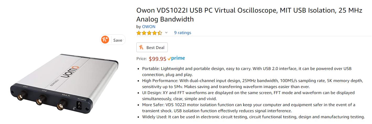
The Owon V1022I
Figure 2-Owon VDS1022I
Analysis:
Although the rise time of the Owon was pretty low compared to other USB oscilloscopes at a value less than 14ns and a recording of a circuit up to 120 Volts being compatible with the circuit the overall bandwidth of this oscilloscope was deemed to low considering the price of $100. The software that comes with the circuit was also described as not being user friendly, as it was stated to only run exclusively with drop down menus.
Option 2
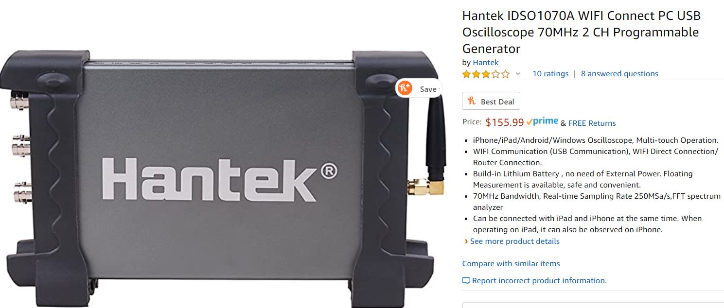
The Hantek IDSO170A
Figure 3-Hantek IDSO170A
Analysis:
The Hantek was built better than alot of other oscilloscopes according to its specs. The rise time on the Hantek was described to be less than 5 ns. It was with the Hantek oscilloscope that we found that increasing the bandwidth by 50 MHz would be a near $100 rise in oscilloscope prices. The Hantek oscilloscope also had an application to run off the Ipad as well. Unfortunately, when trying to order the oscilloscopes it was around early April. The estimated time to ship the Hantek Oscilloscope was April 27th. This was not a viable option, as it did not allow us any time to test any of our circuits.
Option 3
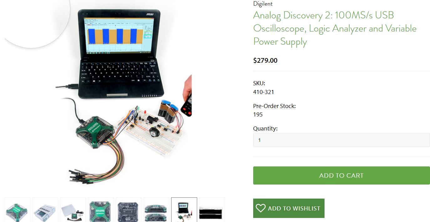
The Analog Discovery 2
Figure 4-Digilent’s Analog Discovery 2
If cost was not an option, the Analog Discovery 2 would be the definite choice of oscilloscope. While the bandwidth of the Analog Discovery is relatively low for the price (30 MHz), the versatility of this oscilloscope is impressive. The Discovery comes packaged with a logic analyzer as well as programmable power supplies (5 Volt rails). For a student in Electrical Engineering, the Analog Discovery has features that go well beyond circuit and power analysis.
[/av_textblock]
[av_hr class=’default’ height=’50’ shadow=’no-shadow’ position=’center’ custom_border=’av-border-thin’ custom_width=’50px’ custom_border_color=” custom_margin_top=’30px’ custom_margin_bottom=’30px’ icon_select=’yes’ custom_icon_color=” icon=’ue808′ av-desktop-hide=” av-medium-hide=” av-small-hide=” av-mini-hide=”]
[av_heading tag=’h1′ padding=’10’ heading=’Implementation’ color=” style=” custom_font=” size=” subheading_active=” subheading_size=’15’ custom_class=” admin_preview_bg=” av-desktop-hide=” av-medium-hide=” av-small-hide=” av-mini-hide=” av-medium-font-size-title=” av-small-font-size-title=” av-mini-font-size-title=” av-medium-font-size=” av-small-font-size=” av-mini-font-size=”][/av_heading]
[av_textblock size=” font_color=” color=” av-medium-font-size=” av-small-font-size=” av-mini-font-size=” admin_preview_bg=”]
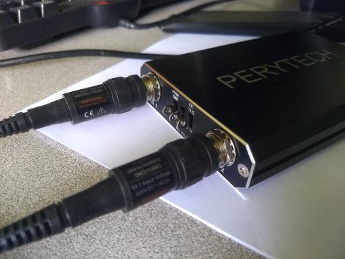
While the other options were considered the oscilloscope we decided on was the Perytech DSO-U2200. The Amazon listing can be found here.
[/av_textblock]
[av_horizontal_gallery ids=’161037,161038,161040′ height=’25’ size=’large’ links=’active’ lightbox_text=” link_dest=” gap=’large’ active=’enlarge’ initial=” control_layout=’av-control-default’ id=”]
[av_textblock size=” font_color=” color=” av-medium-font-size=” av-small-font-size=” av-mini-font-size=” admin_preview_bg=”]
Figure 5-7 – Perytech DSO-U2200
[/av_textblock]
[av_textblock size=” font_color=” color=” av-medium-font-size=” av-small-font-size=” av-mini-font-size=” admin_preview_bg=”]
The Perytech DSO-U2200 was an interesting case. Unlike the Hantek oscilloscope priced at around $160, the Perytech oscilloscope was priced at $110, even though its bandwidth was 60MHz (10 less than the Hantek). The sampling rate of the Perytech oscilloscope has a sampling rate of 240 Ms/s compared to Hantek’s (250 Ms/s). The Perytech seemed to be a budget version of what was offered in the Hantek oscilloscope, although similar to the Analog Discovery, the Perytech also comes packaged in with a Logic Analyzer which adds a second use for the better price.
What was not considered when buying was the support documentation for the oscilloscopes, which caused us trouble whilst trying to set up the Perytech oscilloscope.
[/av_textblock]
[av_heading tag=’h2′ padding=’10’ heading=’Documentation on the Use’ color=” style=” custom_font=” size=” subheading_active=” subheading_size=’15’ custom_class=” admin_preview_bg=” av-desktop-hide=” av-medium-hide=” av-small-hide=” av-mini-hide=” av-medium-font-size-title=” av-small-font-size-title=” av-mini-font-size-title=” av-medium-font-size=” av-small-font-size=” av-mini-font-size=”][/av_heading]
[av_textblock size=” font_color=” color=” av-medium-font-size=” av-small-font-size=” av-mini-font-size=” admin_preview_bg=”]
The manual for the use of a Perytek Oscilloscope can be found here.
[/av_textblock]
[av_textblock size=” font_color=” color=” av-medium-font-size=” av-small-font-size=” av-mini-font-size=” admin_preview_bg=”]
To power on your Perytech Oscilloscope, it must be connected with a standard USB 2.0 cable to your computer. Once connected a red light for power will turn on.
The software for the Perytech can either be installed on disc or through their website, a link can be found within the User-Manual given earlier. It is critical that you if you are to use the Oscilloscope feature you install the file listed under DSO_Install_V2.09.exe. If installing from the disc, the Logic Analyzer is mislabeled under the DSO_Install_LV2.09.exe, so it can be pretty easy to mix them up.
Once launched the Window for the digital oscilloscope is pretty similar to how a regular oscilloscope looks.
[/av_textblock]
[av_image src=’https://www.arxterra.com/wp-content/uploads/2020/05/O-Scope_Interface.png’ attachment=’161045′ attachment_size=’full’ align=’center’ styling=” hover=” link=” target=” caption=” font_size=” appearance=” overlay_opacity=’0.4′ overlay_color=’#000000′ overlay_text_color=’#ffffff’ animation=’no-animation’ admin_preview_bg=”][/av_image]
[av_textblock size=” font_color=” color=” av-medium-font-size=” av-small-font-size=” av-mini-font-size=” admin_preview_bg=”]
Figure 8 – Perytech User Interface
[/av_textblock]
[av_textblock size=” font_color=” color=” av-medium-font-size=” av-small-font-size=” av-mini-font-size=” admin_preview_bg=”]
To use the probes properly the BNC cables must be hooked up properly, such as in Figure 6. Once active, a green light will appear, showing that the signal is triggered. At this point the channels can be enabled by selecting the CH1 and CH2 buttons. CH1 appears in green, while CH2 appears in red. From this point the trigger must be set by going from >slope to: >auto for the automatic wave pattern, >normal for the wave pattern to appear only when triggered, or >single to stop the wave cycle after one trigger.
[/av_textblock]
[av_image src=’https://www.arxterra.com/wp-content/uploads/2020/05/backemf-spikes.jpg’ attachment=’161047′ attachment_size=’full’ align=’center’ styling=” hover=” link=” target=” caption=” font_size=” appearance=” overlay_opacity=’0.4′ overlay_color=’#000000′ overlay_text_color=’#ffffff’ animation=’no-animation’ admin_preview_bg=”][/av_image]
[av_textblock size=” font_color=” color=” av-medium-font-size=” av-small-font-size=” av-mini-font-size=” admin_preview_bg=”]
Figure 9 -Back EMF Generated Voltage (Red)
[/av_textblock]
[av_heading tag=’h1′ padding=’10’ heading=’Conclusion’ color=” style=” custom_font=” size=” subheading_active=” subheading_size=’15’ custom_class=” admin_preview_bg=” av-desktop-hide=” av-medium-hide=” av-small-hide=” av-mini-hide=” av-medium-font-size-title=” av-small-font-size-title=” av-mini-font-size-title=” av-medium-font-size=” av-small-font-size=” av-mini-font-size=”][/av_heading]
[av_textblock size=” font_color=” color=” av-medium-font-size=” av-small-font-size=” av-mini-font-size=” admin_preview_bg=”]
Once your triggers are setup, you should be able to properly view your waveform. For the Sojourner project, the Perytech Oscilloscope was critical in finding the delay time of the voltage created due to the back emf. Sojourner’s digital values had to be implemented through carefully observing the time within these delays, as running tests through ADC and trying to guess our way through that would give us inaccurate and insufficient information.
[/av_textblock]
[av_heading tag=’h1′ padding=’10’ heading=’References’ color=” style=” custom_font=” size=” subheading_active=” subheading_size=’15’ custom_class=” admin_preview_bg=” av-desktop-hide=” av-medium-hide=” av-small-hide=” av-mini-hide=” av-medium-font-size-title=” av-small-font-size-title=” av-mini-font-size-title=” av-medium-font-size=” av-small-font-size=” av-mini-font-size=”][/av_heading]
[av_textblock size=” font_color=” color=” av-medium-font-size=” av-small-font-size=” av-mini-font-size=” admin_preview_bg=”]
https://www.perytech.com/Product/USB-Oscilloscope/Doc/DSO%20Manual-En.pdf
[/av_textblock]
[/av_one_full]


