Goliath Bluetooth Module HC-06 Test
By: Tae Min Lee (Mission, Systems, and Testing Engineer)
One of the requirements of the Goliath was using the Arxterra Control Panel and the Arxterra application. Since, the 3Dot board was not given at the time we had to find an alternative to test the Bluetooth module (HC-06). Before we start using the Arxterra application we performed a basic test on the Bluetooth module. The purpose of this test was to determine the communication between the Bluetooth module and the android device.
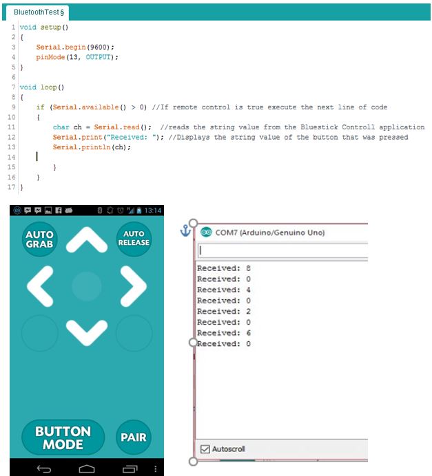
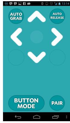
We used an android application called BlueStick Control on an android phone. The following code shown above was uploaded to the Arduino Uno along with the Bluetooth module. By pressing the up key the serial monitor returned a string value 8 corresponding to the key that was just pressed. The next string value 4 corresponds to left, string value 2 corresponds to down and string value 6 corresponds to right. The zero value shows the default string value it returns to as the user lets go of the key (shown above).
The tutorials to test the Bluetooth module came from instructables to test out the basic functions of a Bluetooth module. We performed a test of the code to see the communication between the Arduino Uno with the HC-06 Bluetooth module. We tested to determine the output interface for our lasers and motor control.
Components Used:
- Bluetooth Module (HC-06)
- Wiring Kit
- Arduino Uno
- Motor
- Laser Module
- Arduino IDE
- Arduino Motor Shield
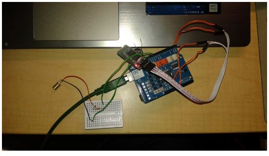
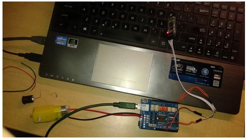
The following circuit shown below was used to test the laser shot control using an Arduino Uno, laser module, and the Bluetooth module.
Modifying the code shown earlier we can control the laser shots by pressing a button from our android device that will be communicating with the Arduino Uno through a Bluetooth Module. See the following code:
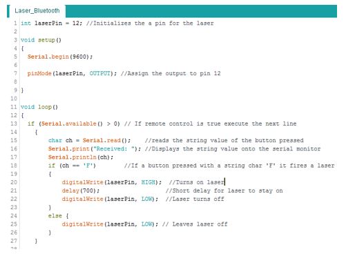
The code will set the laserPin HIGH (turn on laser) when the button with the string character ‘F’ is pressed.
The next test was performed to see if the android device was able to communicate with the Bluetooth Module that was connected with both the Arduino Uno and the Arduino Motor Shield (shown below).
The following code will be used to implement the motor control that will be used on the Arduino Uno and the Arduino Motor Shield:
const int //Declaring all the pins used for motor 1 and motor 2
//Motor 1
PWM_A = 3,
DIR_A = 12,
BRAKE_A = 9,
SNS_A = A0,
//Motor 2
PWM_B = 11,
DIR_B = 13,
BRAKE_B = 8,
SNS_B = A1,
laser = 6;
void setup()
{
// Intializes the output and input for the pins
pinMode(BRAKE_A, OUTPUT);
pinMode(DIR_A, OUTPUT);
pinMode(BRAKE_B, OUTPUT);
pinMode(DIR_B, OUTPUT);
Serial.begin(9600);
}
void move()
{
digitalWrite(BRAKE_A, LOW); // settig the brake LOW to disable motor brake
digitalWrite(DIR_A, LOW); // now change the direction to forward setting LOW the DIR_A pin
analogWrite(PWM_A, 250);
digitalWrite(BRAKE_B, LOW); // now change the direction to forward setting LOW the DIR_B pin
digitalWrite(DIR_B, LOW);
analogWrite(PWM_B, 250);
}
void brake()
{
digitalWrite(BRAKE_A, HIGH); //Sets the brakes for both motor 1 and motor 2
digitalWrite(BRAKE_B, HIGH);
}
void backward()
{
digitalWrite(BRAKE_A, LOW); // setting againg the brake LOW to disable motor brake
digitalWrite(DIR_A, HIGH); // now change the direction to backward setting HIGH the DIR_A pin
analogWrite(PWM_A, 250);
digitalWrite(BRAKE_B, LOW); // setting againg the brake LOW to disable motor brake
digitalWrite(DIR_B, HIGH); // now change the direction to backward setting HIGH the DIR_A pin
analogWrite(PWM_B, 250);
}
void turnRight()
{
digitalWrite(BRAKE_A, LOW); // setting againg the brake LOW to disable motor brake
digitalWrite(DIR_A, HIGH); // now change the direction to backward setting HIGH the DIR_A pin
analogWrite(PWM_A, 250);
digitalWrite(BRAKE_B, LOW); // setting againg the brake LOW to disable motor brake
digitalWrite(DIR_B, LOW); // now change the direction to forward setting LOW the DIR_A pin
analogWrite(PWM_B, 250);
}
void turnLeft()
{
digitalWrite(BRAKE_A, LOW); // setting againg the brake LOW to disable motor brake
digitalWrite(DIR_A, LOW); // now change the direction to forward setting LOW the DIR_A pin
analogWrite(PWM_A, 250);
digitalWrite(BRAKE_B, LOW); // setting againg the brake LOW to disable motor brake
digitalWrite(DIR_B, HIGH); // now change the direction to backward setting HIGH the DIR_A pin
analogWrite(PWM_B, 250);
}
void stop()
{
digitalWrite(BRAKE_A, HIGH);
digitalWrite(BRAKE_B, HIGH);
}
void loop()
{
// put your main code here, to run repeatedly:
char ch = Serial.read();
Serial.print(“Received: “);
Serial.println(ch);
if (ch == ‘8’) //Move forward
{
move();
delay(1000);
stop();
}
}
The code shown above will only implement the move forward function by calling on the sub routine move. By adding else if statements we can implement a turn right, turn left, or backwards.
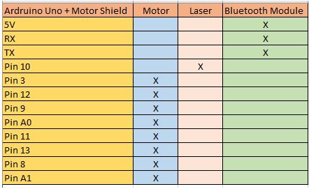
The overall pins that we will be using on the Arduino Uno is shown below:
Sources:
- http://www.instructables.com/id/Add-bluetooth-to-your-Arduino-project-ArduinoHC-06/
- https://www.arduino.cc/en/Main/ArduinoMotorShieldR3
- https://www.arduino.cc/en/Reference/DigitalWrite