By: Kevin Moran (Electronics and Control Engineer), Tae Lee (Systems- Provided the musical notes code needed for this game)
In this post, I will be discussing the final results for the IR Emitter when being used alongside with a Schmitt Trigger and the code that will be used to determine when the 3DoT Rover gets hit 3 times by an IR emitter.
I will first show below what happens when this final circuit is connected to an Arduino analog pin, although the Schmitt trigger is technically used to convert an analog signal to digital, I feel it is important to understand these changes in analog first.
- I first tested the output by connecting it to the Analog input of my Arduino Uno
- The final output of the signal by using the correct resistors values has very little noise and it is controlled within our 0-5V range
- When the IR light hits the receiver, the signal from the photo-transistor is passed by the Schmitt trigger. This trigger then inverts the signal, and reduces the noise from the input giving us the output shown here.

As can be seen this signal is inverted from the original IR receiver signal, and the final output has relatively zero noise.
Since this trigger is an analog to digital converter, I also decided to test the output with a digital Arduino pin.
- I decided to test the circuit with an Arduino Digital Input (2) just to ensure if asked, the PCB would work with either analog or digital input.
- The concept is the same, except the outputs are either 0v or 1v.
- The signal in the output is different from the analog output, they are peaks.
- As you can see from the Arduino plotter, the circuit detects the IR light faster, and counts more hits/second.

However upon closer inspection, I was told my output is not supposed to be spiked, but rather look similar to the analog output. One reason might be the Op-Amp I was told to use. I will continue testing and resolve this issue.
The Code:

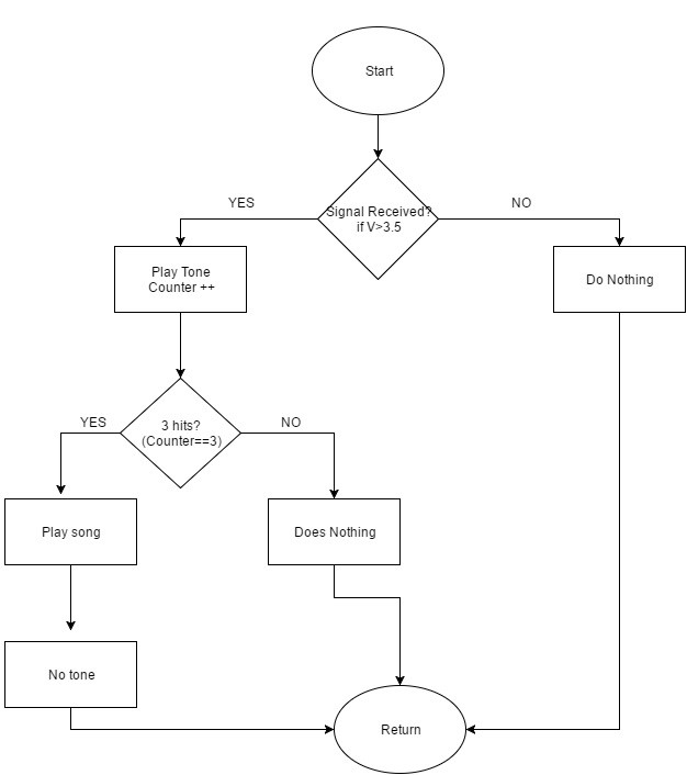
This code is used to track the number of hits on the 3DoT Rover when testing with the analog pin. It consists of a loop that is activated once the voltage on the receiver reaches 3.5v, and counts the number of times it reaches this level or higher. Below I present the pseudo code and the flow chart in hopes of better explaining this code.

Flowchart:

Once the micro-controller detects 3 hits, it will play a short song and then reset, and start over again.
Sources:
https://www.arduino.cc/en/Tutorial/ReadAnalogVoltage