By: Kevin Moran (Electronics and Control Engineer)
In this post I will be discussing my initial selection for the IR receiver and how I began testing its analog output.
Components:
Transistor: SFH 310 (Opto Semiconductor)
Resistor: 2M ohm
IR light
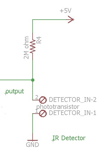
The phototransistor is a two legged transistor, with its third input being the output of the IR LED (Infrared Light).
- When a light is shined, the electrons begin to diffuse from the emitter to the collector, this causes a voltage drop from its original 5V.
- Unfortunately this signal is noisy and trying to use it directly for a game of laser tag would be very difficult. I present below the analog output of this transistor.
Arduino Plotter Graph:

Arduino Monitoring:

As can be appreciated from both the plotter and the monitor plots of the Arduino software, this analog signal is all over the place, the voltage drops varies depending on the distance of the LED from the receiver, and the length of time the light actually hits the receiver. Playing a game of laser tag with these results would not be very appropriate. The noise levels when no IR light is hitting the receiver are also shown on the Arduino plotter graph.
Note: The resistor value of 2M was chosen based on testing the sensitivity of the receiver with various values. 2 mega ohms turned out to be the best result
The code:
To read the analog voltage output

Eagle Cad Schematic:

Sources:
Jeff Cool: Division Manager