By: Adolfo Jimenez (Manufacturing)
Verified By: Jordan Smallwood (Project Manager)
Approved By: Miguel Garcia (Quality Assurance)
Table of Contents
Introduction
In order to test the articulation of the solar panels before they were assembled onto the chassis an EasyDriver stepper motor driver was used to run and test the motors, and thus by extension the solar panels. Stepper motors can move an exact amount of degrees (or steps) when programmed to do so. This gives us total control over the motor, allowing us to move it to an exact location and hold that position. This is done by alternating power sent to 2 separate coils inside the motor at fractions of a second. A stepper motor combined with a motor driver and microcontroller allows us to dictate the speed and amount of steps taken in any direction making them ideal for our solar panel articulation system.
Parts Used
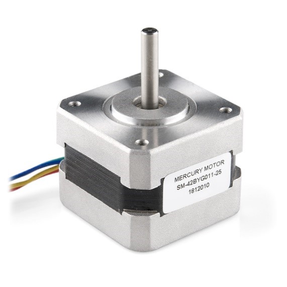
- Bipolar Stepper Motor (ROB-09238)
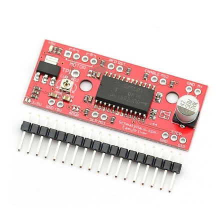
- EasyDriver – Stepper Motor Driver (ROB-12779)
- Arduino UNO
- Breadboard, Wires, 10k Resistor (x2), 12V Power supply
Figure 1: Typical Stepper Motor
Figure 2: Sparkfun Easy Driver
Assembly
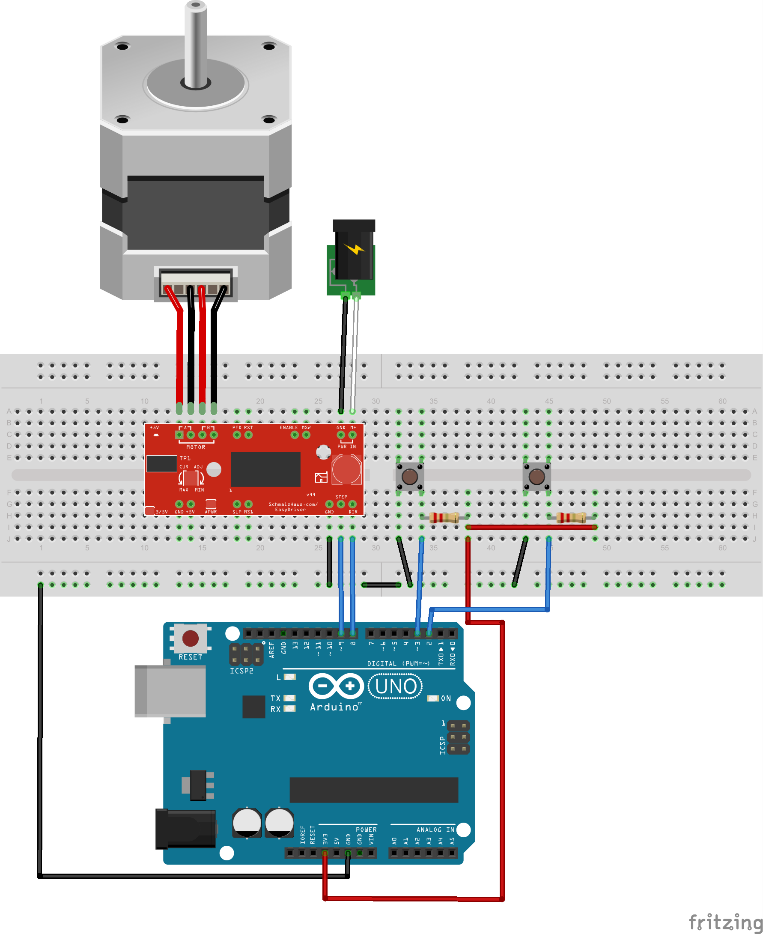
First, the board needed to be assembled, that was a quick and easy job requiring the soldering of the 17 included header pins onto the board. The next step was wiring the entire setup, to do this we first needed to identify which of the four wires pertained to each coil wire pair within the motor. Looking at the datasheet for this stepper motor we can see that the red and green wires form one coil, while the yellow and blue form another. To test this, an LED can be connected to a wire pair on each lead. If the LED blinks while manually turning the motor shaft then those two cables indeed form a coil. The first coil pair should be plugged into Coil A+ and Coil A-, while the second coil pair plugs into Coil B+ and Coil B-. After further research it was discovered that there is no polarity on the coils, so you need not worry about plugging in a coil backwards onto the board. As per the specifications on the datasheet for the motor, a 12-volt power supply was selected to power the motor. All remaining connections can be seen in the following fritzing diagram:
Figure 3: Fritzing Diagram for Simple Stepper Motor Operation
Code
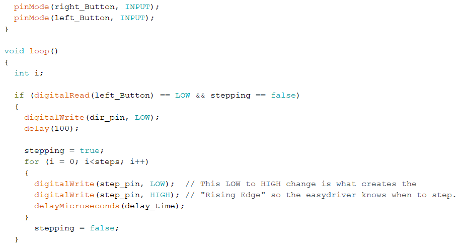
With the physical circuit built the following code was uploaded onto the Arduino UNO to begin controlling the motor. When the code is running, it waits for a button press (a LOW on Arduino pin 2 or 3) and then begins to rotate the stepper motor for the programmed number of steps. A push button switch was added between Pins 2, 3, and ground, with an accompanying 10K pull up resistor used for each pin at 3.3V. For this set up, pin 3 associated with the button on the left (LOW on pin 3) turned the motor clock wise, the button on the right (LOW on pin 2) rotated the motor counter-clockwise.
Figure 4: Code for Simple Operation of Stepper Motors
Conclusion
Utilizing this described setup I was able to test the stepper motors and begin working on the solar panel articulation for our rover. Messing with the code I found that using the motor at slower speeds appeared to provide me with more torque as spinning it at a slower RPM provided the greatest resistance against pressure applied on the shaft by squeezing it with my fingers. One thing to really note is the current adjustment potentiometer on the EasyDriver. I recommend that while the code is running, with a small screw driver slowly turn the potentiometer one way or the other. Depending on the type of motor you use (mainly its coil resistance) you may notice a difference as different current values might operate the motor much more smoothly than others.


