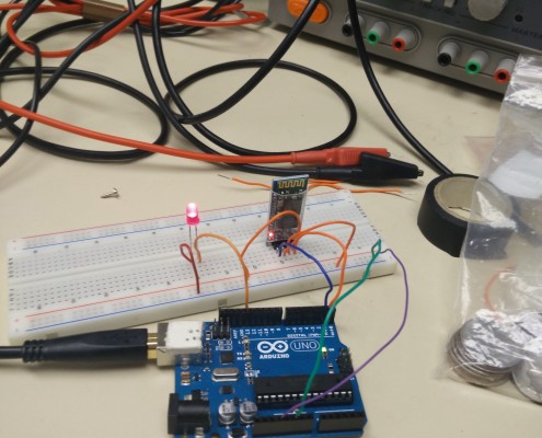
HC-06 Test, It Works
By: Ameen Alattas
In order for to meet the requirement8, level 1 to communicate with the BiPed through Arxterra application, the group needs to use a Bluetooth device V2 Class 2 to use the application to send commands through an Android phone. The group decided to choose the HC-06 because of its recommendation, its ease of use, its inexpensive ($4.50) and works only as a slave. Click this link to see where the group obtained its set up for the test. Keep in mind to connect any device with the Bluetooth a password is needed, which is ‘1234’. Moreover, Disconnect whatever pin is connected to RXD pin_0 in the arduino before uploading the code. To test the Bluetooth after uploading the code the user goes to the serial monitor and enters the letter ‘N’, the Bluetooth should turn on and when the letter ‘F’ is entered the Bluetooth will turn off.
*Note: The code was taken from the same link above.
*This link will take one to the Decision Tree Arxterra Test, were the group tested the direction of RC mode and control panel using the HC-06.
HC-SR04 Test
By: Ameen Alattas
Since one of the requirements is for the BiPed to avoid obstacles, the micro BiPed team decided to use HC-SR04 ultrasonic sensor to work as the BiPed vision. The reason it was decided to use the HC-SR04 is because one was in inventory. To test the sensor the schematic from http://arduinobasics.blogspot.com/2012/11/arduinobasics-hc-sr04-ultrasonic-sensor.html was used to connect the sensors with the Arduino using a breadboard. The code used to test the sensors was taken from http://treehouseprojects.ca/ultrasonictutorial/. The range of the sensors is 2cm – 396cm(4m).Since the safe zone choice was 5cm, if any object is closer than 5cm the LED will be on which mean the sensor is activated to help the BiPed to avoid objects in its way. For now, when the BiPed sense an obstacle within 5cm it will avoid whatever on its way until we build the actual BiPed and see if 5cm is enough to avoid an obstacle without hitting it.
Gyro
Since the BiPed is supposed to walk in a human-like fashion and it has to stabilize when disturbed by a force, using a gyroscope is essential for this project. The gyroscope will measures the angular rates of rotation (X,Y,Z) and measure the current orientation of the BiPed relaying the information to the microcontroller, which in turn keep the BiPed balancing by sending signals to the servos to rotate in away to help the BiPed walk in human-like or to balance itself when it disturbed by a force. At first the L3GD2000 was chosen, but after testing it was noticed that the Y-axis was always negative no matter what the direction of rotation of the gyroscope. Therefore, it was decided to change the gyroscope to the MPU 6050. Although it is not the same type of gyro, previous semesters used the MPU6050 and had good amount of success with it. The connection for the MPU6050 is straightforward. SDA and SCL pins will connect respectively with SDA and SCL on the arduino micro and GND to GND and VCC to power source. In addition, the gyro can issue an external interrupt if it is desired.
From the data shown above, the MPU6050 contains three-axis accelerometer and a three-axis gyroscope. As the chip started to rotate, it was observed that the accelerometer measures the smallest of movement. Likewise with the gyroscope, but its not as sensitive as the accelerometer; however, it will still help the BiPed maintain stability.
The code and set-up used for the gyro can be found at the Arduino site.


