Goliath Fall 2017
Initial Design
By: Vanessa Enriquez (Manufacturing Engineer)
Approved by: Mark Huffman (Project Manager)
After inspecting last year’s final product, I began to redesign the dimensions of the overall body of the tank. While reviewing their SolidWorks’ files, I calculated a maximum possible decrease in width of 8.95 mm. The following changes were made in order to minimize the overall width of the tank and other changes were to satisfy the requirements that were derived in our preliminary plan.
Preliminary Sketches
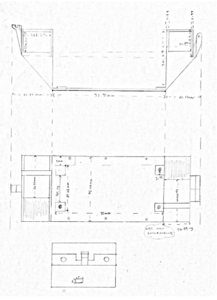
Changes made to the bottom panel include relocating the motors, i/o access cut-out, and realigning all parts. In figure one, I placed the motors in alternate positions on opposite sides of the PCB. This resulted in a decrease in width from 53.98 mm to 45.03 mm. The length was also affected, it is estimated to be 115.45 mm. A 5×5 mm i/o access cut-out was placed in the rear of the bottom panel. Our PCB will have to be flipped to align the i/o port to the cut-out. Lastly, all other parts were recentered to the new width dimension.
Figure 1 – Bottom Panel Preliminary Sketch
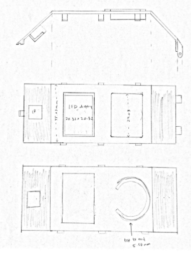
The top panel changes were made to compliment the bottom panel resize. A 20.32×20.32 mm LED display cut-out and an IR sensor cut-out were added to the top as shown in figure two below. All excess cut-outs were removed.
Figure 2 – Top Panel Preliminary Sketch
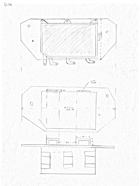
The left-side panel changes included gear and wheel alignment, added wire loops and getting rid of the wings from the previous design. The added loops shown in figure three will be used to maintain the wires away from the center when connecting from the bottom to top panel. The wings used for the sonar sensors are no longer useful. So the entire wing design was removed.
Figure 3 – Side Panel Preliminary Sketch
Calculations
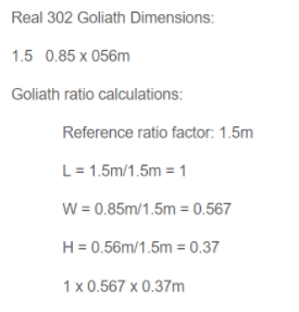
The ideal dimension ratio was calculated by using the actual 302 dimensions of LxWxH, 1.5×0.85×0.56 meters [1]. The actual 302 tank ratio is 1×0.56×0.37 while using the L dimension 1.5m as the reference ratio factor.
Figure 4 – Real 302 Goliath ratio calculations [3]
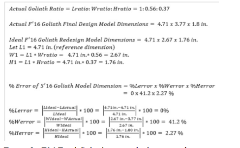
Last year’s final model calculations are shown in figure 5. The %Werror was relatively high at 41.2%. This was calculated by using a reference factor of 4.71 inches. By reducing the width, I can obtain a more accurate scaled-down model of the actual 302 tank. The sum of the %error of F16 based on the 4.71 in. reference factor is 43.47%.
Figure 5 – F16 Final Goliath ratio calculations and percent error
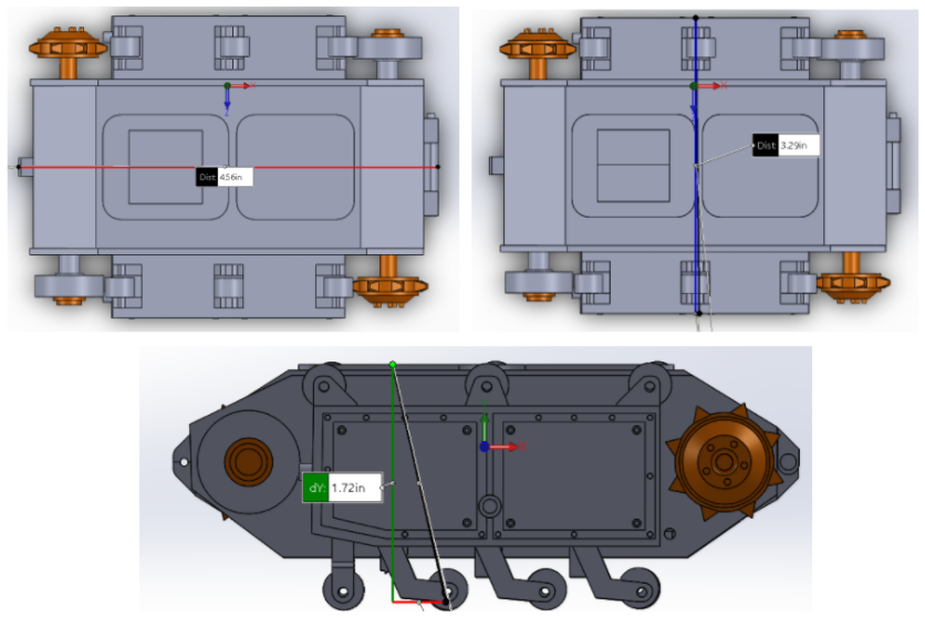
After modifying the 3D model on solidworks I measured the components and the dimensions are currently 4.56×3.29×1.72 inches.
Figure 6 – F17 Goliath dimensions
By using the current length dimension (4.56 in.) as the reference, the ideal height and width for the F17 goliath were calculated below.
Given: Lratio:Wratio:Hratio = 1:0.567:0.37
F17 initial Goliath Dimensions: 4.56×3.29×1.72 inches
Ideal F17 Goliath ratio calculations:
Reference factor: 4.56 in.
L = 4.56*Lratio = 4.56in*1 = 4.56 in
W = 4.56*Wratio = 4.56in*0.567 = 2.59 in
H = 4.56*Hratio = 4.56in*0.37= 1.69 in
F17 ideal Goliath dimensions: 4.56×2.59×1.69 inches
Ideally, the scale down model will measure 4.56×2.59×1.69 inches; whereas, the actual dimensions are 4.56×3.29×1.72 inches. The sum of the %error of F17 based on the 4.56 in. reference factor is 28.8%.
F17 initial Goliath Dimensions: LinitialxWinitialxHinitial = 4.56×3.29×1.72 inches
F17 ideal Goliath dimensions: LidealxWidealxHideal = 4.56×2.59×1.69 inches
% Error F17 Goliath Dimensions = %Lx%Wx%H = 0x27.02×1.78 %
%L = [|(Lideal-Linitial)/Lideal|]*100 = [|(4.56-4.56)/4.56|]*100 = 0%
%W = [|(Wideal-Winitial)/Wideal|]*100 = [|(2.59-3.29)/2.59|]*100 = 27.02%
%H = [|(Hideal-Hinitial)/Hideal|]*100 = [|1.69-1.72)/1.69|]*100 = 1.78%
As of now, the %W is over 14% lower than the F16 final model. There was also a decrease in %H of 0.49% [2].

