I2C PWM IC and Color Sensor Long Range Research Studies
By Malak Alamad | Sojourner Team | F17
Color Sensor Study:
(Updated 12/8/17)
Intro:
In order to properly accomplish our tasks and requirements for the assembly of the small-scale version of the Sojourner Mars rover, I conducted a research study regarding the color sensors. I wanted to find out of there was any way to expand the viewing range of the sensors, without replacing them. After some research, I found that there are three ways to accomplish this: light, magnification, or blinders.
Discussion:
While working on our project and picking out color sensors, we decided to use the TCS34725 color sensor. When we discussed its purpose and design, it will be used to detect the path in the maze, so that the rover can find its way through. We also thought that there should be a way to possibly increase the viewing range of the sensor for better accuracy. After doing some research, I found that there are three possible ways to improve the viewing range of the color sensor, including lights, blinders, and magnification.
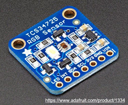
One way to improve the viewing range of the color sensor is by adjusting the lighting. By using a high intensity white LED, the surrounding brightness will increase, thus, the colors that the sensor is trying to detect become more defined, which will improve its viewing ability. The con to this option is that it will use too much power. Another option is to use blinders on the sensor. If we put blinders, we can use them to control the sensor’s field of view and only have it see what we want it to see. The third option would be magnification. By using a magnifying lens, we could focus the light on the detector, which will make it easier for the sensor to detect the colors it is looking for. One option that is not very concrete is decreasing the distance between the sensors and the color it is viewing. There is no clear definition of how far the color sensor can view, because there are many different factors that play a part in its viewing range. But the accuracy could possibly be increased if we have our color sensor closer to the ground in order to detect the path within the maze. The specific color sensor we are using is shown below.
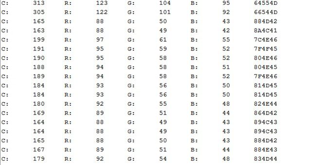
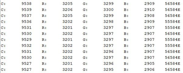
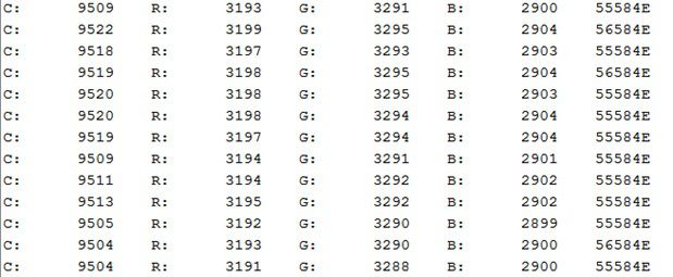
I conducted an experiment to see how well the third method, magnification, would work. Using a black sheet of paper, the color sensor, a 2x lens, an Arduino board, and code I found on Adafruit, I tested the viewing distance of the sensor. Without the lens, the color sensor was able to detect the color of a black piece of paper from 3 mm. Once it reached 4 mm away from the paper, the RGB values spiked and were no longer accurate. When I attached the lens, which was 12 mm high, I began increasing the distance to see if the magnifying glass would increase the viewing range. Once the sensor was 15 mm away from the paper, the RGB values spiked.
RGB Values without Lens at 3 mm:
RGB Values without Lens at 4 mm:
RGB Values without Lens at 12 mm:
RGB Values without Lens at 15 mm:
Conclusion:
From the conducted experiment, I concluded that the magnifying method does not work, and we will not incorporate it into our design. Based on the data found with the lens, the RGB values spiked to about 3000, so I believe that the data is not accurate due to refraction. Because the LED from the sensor is on the inside of the lens, the light affected the results because it didn’t allow for the sensor to see through the lens. Instead, the light was reflected to the sensor and caused erroneous results. If the LED was placed below the lens, the results would have been conclusive. This method is no longer a viable option.
I2C PWM IC Study:
By Malak Alamad
Intro:
In order to properly accomplish our tasks and requirements for the assembly of the small-scale version of the Sojourner Mars rover, I conducted a research study regarding the I2C PWM IC. I measured the current draw, researched its functions, and found how it will be used in the rover.
Discussion:
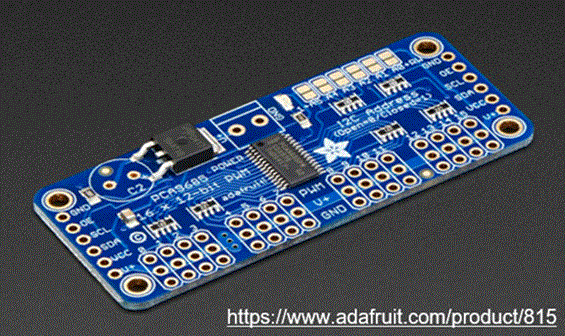
The I2C PWM IC, specifically the PCA9685, is an I2C that is a 16 channel, 12-bit controller. It is a multiplexer that allows for an increased number of outputs for a set number of inputs. It can be configured for a total of up to 992 outputs. For the purpose of the project, we are using this PCA9685 to increase the number of outputs. Utilizing this I2C allows us to make use of the SDA and SCL pins, which are the data signal and clock signal pins, respectively. This clock pin allows the I2C to continuously update its data and automatically send its signals directly to a microcontroller, which in our case is the 3dot. The data pin stores the data. During each clock pulse, one data bit is transferred to the data pin. This process continues until the I2C is no longer in use. Using the SDA and SCL pins of this I2C allows for the GPIO pins to be free, thus, allowing for more input and output pins. One thing that makes this multiplexer unique is that each pin has its own unique address. The reason we chose to use this specific I2C is because of the number of channels it has so we can use it as a hub for our inputs and outputs, it has a low current draw of 7.97 mA so it won’t need a lot of power, and it’s inexpensive so that it can fit our project budget. Below is an image of the specific model we will be using for our rover.

