Goliath Fall 2017
Preliminary Design Document
Mark Huffman (Project Manager)
Vanessa Enriquez (Manufacturing Engineer)
John Ocampo (Electronics and Controls Engineer)
Nornubari Kanabolo (Missions and Systems Engineer)
Program Objective
By Mark Huffman (Project Manager)
Objective
The Goliath tank will participate in a set of events taking place on a maze with an overlaid grid matrix. The first event will be navigating the maze first under remote control then autonomously repeating the same driven route. A second event will involve other robots located within the same maze space. In this event, the goal is to navigate out by, following the rules of the maze and a known route. This is based on the game plan set by the project managers.
Our Goliath tank will build on the progress set by the fall 2016 semester, with a reassignment to the new mission. We plan to make the Goliath smaller and relocate the motors to remove excess space inside the chassis. Then our plan is to add forward sensing for avoiding collisions, color sensors to track the maze and an LED grid display for displaying direction and other information.
Past Requirement Analysis
Fall 2016 Level 1 Requirements Analysis
By Mark Huffman (Project Manager)
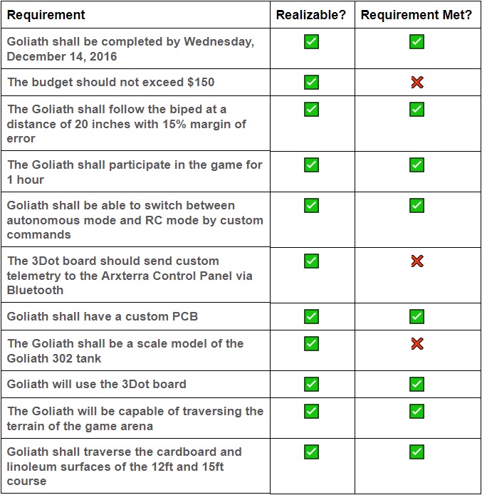
All of their requirements are defined correctly and use the words “should”, “will” and “shall”. There is a clear definition between set requirements that must be meet and requirements that are more-or-less meant to be attempted addons.
The budget should not exceed $150 – Was a solid and realizable goal however they encountered unexpected costs. They should have left room some room in the budget for error and uncertainties with parts and printing.
The 3Dot board should send custom telemetry to the Arxterra Control Panel via Bluetooth – They did use the arxterra control panel to send telemetry commands, it turns out that they didn’t have to make an custom code as they found something to reuse. Great for the schedule and good use of a suggested requirement.
The Goliath shall be a scale model of the Goliath 302 tank – They made a ton of design improvements over the previous group. They did achieve a small tank design that has design characteristics from the actual tank however, they failed to meet exact “scale” dimensions.
Fall 2016 Level 2 Requirements Analysis
By Nornubari Kanabolo (Missions and Systems Engineer)
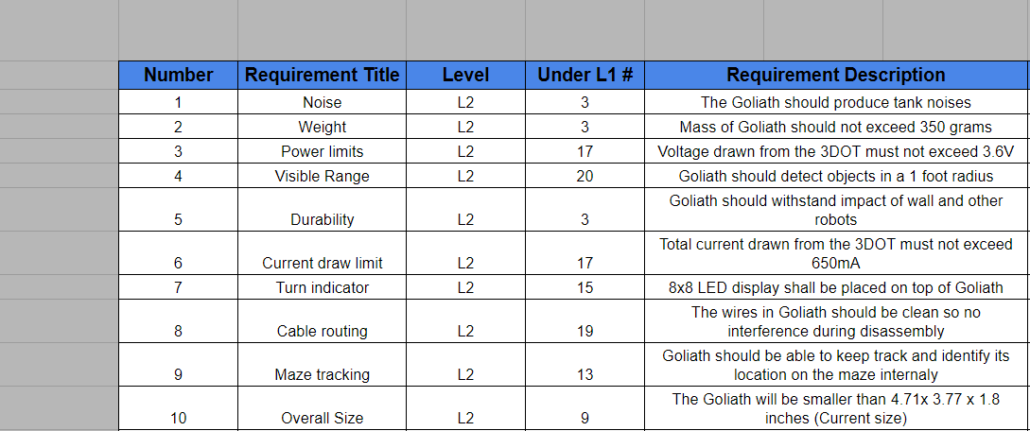
Goliath should make motor noises during the game that fall between 20 to 65dB– This goal is innovative, but specifying that the tank should make motor noises between a certain range made this a harder requirement to meet. They should have just tried to make the Goliath produce tank noises
The Goliath should have an approximate ratio of 1 : 0.566 : 0.373– This ratio is ideal for a scaled model of the Goliath, but with the size of motors and other parts, these dimensions are not realizable. Perhaps smaller parts and better cable routing could have been implemented
Goliath will not surpass a mass of 2.7688 g– This mass is ideal but could be made smaller through the use of less material. This is what we plan to do.
Fall 2016 Level 2 Electronic Sub-Requirements Analysis
By John Ocampo (Electronics and Controls Engineer)
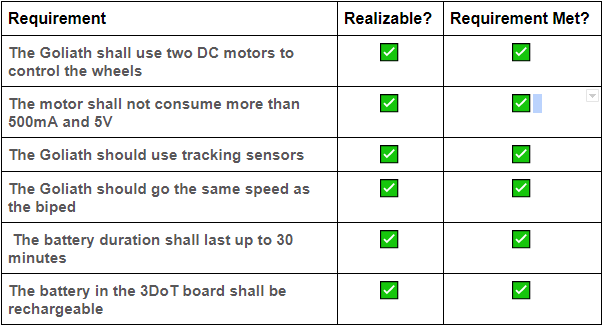
It seems like our predecessor successfully achieved these goals through post-measurements rather than a proposed necessity. An example of this is the 2nd sub-requirement, “… not [consuming] more than 500mA and 5V” and the 5th sub-requirement, “… shall last up to 30 minutes”. These examples seem like they were measurements turned into requirements. The previous group most likely achieved these goals through prior component testing rather than planned design.
They were, however able to achieve a design requirement such as the “tracking sensors”. They created and coded a triangular system that uses the tracking sensors. In addition to that system, they also designed wings onto the Goliath which extended the range of two sensors causing an increase in the effective range or the sight of the triangular system.
Fall 2016 Level 2 Manufacturing Sub-Requirements Analysis
By Vanessa Enriquez (Manufacturing Engineer)
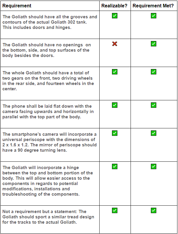
The previous Goliath group project was able to meet all L2 requirements listed above, we plan to build on their success and improve the overall design in terms of size.
The Goliath should have all the grooves and contours of the actual Goliath 302 tank. This includes doors and hinges. The previous semester was successful in realizing this requirement because in researching the structure of Goliath 302, the manufacturing engineer was able to attain the blueprints to build on.
The whole Goliath should have a total of two gears on the front, two driving wheels on the rear side, and fourteen wheels in the center. Aside from the two driving wheels and gears, the tank has seven wheels on either side that mimic the 302 tank design.
The Goliath will incorporate a hinge between the top and the bottom portion of the body. This will allow easier access to the components in regards to potential modifications, installations and troubleshooting of the components. After replacing the snap on hinge between the top and bottom panels, The design incorporated a rod for easier access to the inside for troubleshooting.
Requirements
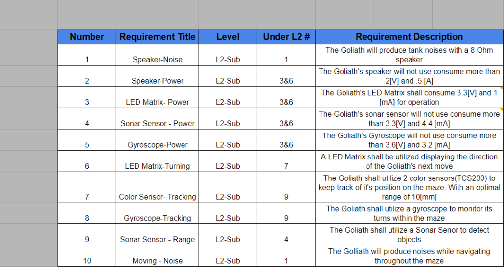
Fall 2017 Level 1 Requirements
Fall 2017 Level 2 Requirements
By Nornubari Kanabolo (Missions and Systems Engineer)
Fall 2017 Level 2 Electronic Sub-Requirements
By John Ocampo (Electronics and Controls Engineer)
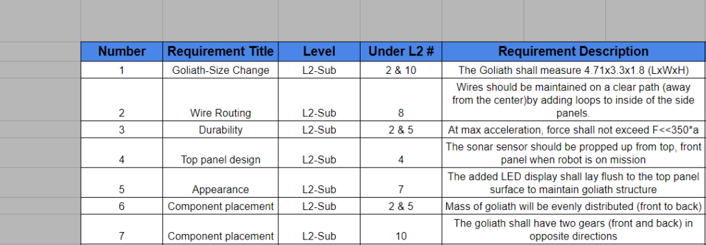
Fall 2016 Level 2 Manufacturing Sub-Requirements Analysis
By Vanessa Enriquez (Manufacturing Engineer)
Design Changes/Innovation
By Mark Huffman (Project Manager)
Creative Solutions
Using the taught creative methods, we created several creative solutions to some of our difficult problems. Our problems involved reducing the overall size, choosing detection methods, physical connection placement and deciding on control methods when other bots are detected. Using brainstorming we determined that using a Bluetooth device would allow us to switch the operating mode of the bot when needed. When tackling the problem of dealing with other bots we decided to look from the point of view of a real driver we determined that when something crosses your path, you stop and then move again when they are further away. For connect placement, we decided that placing a cutout on the physical design would allow easy charging access. In order to reduce the overall size, we brainstormed and determined that if we relocate the motors and relocate components we can shrink some of the tanks overall dimensions.
Systems and Subsystem Design
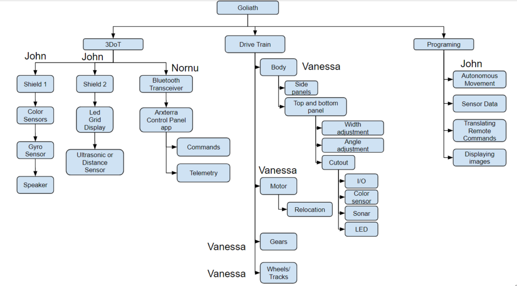
Project Breakdown Structure (PBS)
By Nornubari Kanabolo (Missions and Systems Engineer)
Project Breakdown Structure is the breakdown of the various systems of a given product. They are usually composed of hardware, software, and systems that send and receive information. The Goliath is broken down into the 3DoT board, mobility, camera, and battery. The 3DoT allows for the control of the sensors and Bluetooth. Mobility provides control of the body, motors, gears, wheels, and tracks. Camera allows visibility through a periscope. The battery provides power to the whole robot.
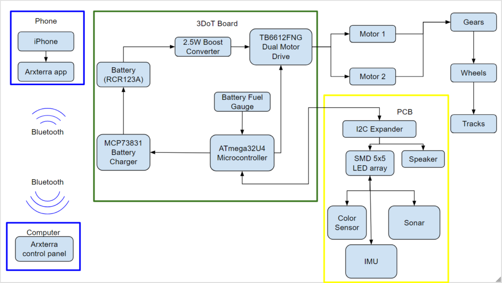
Electronic – System Block Diagram
By Nornubari Kanabolo (Missions and Systems Engineer)
System block diagrams illustrate how each component of the Goliath communicates and connects with each other. With the new 3DoT board there is no need to obtain a Bluetooth module since it has a built-in Bluetooth transceiver. A rechargeable battery is also built into the board, which powers all components connected to it.
Electronic – Interface Diagram
By Nornubari Kanabolo (Missions and Systems Engineer)
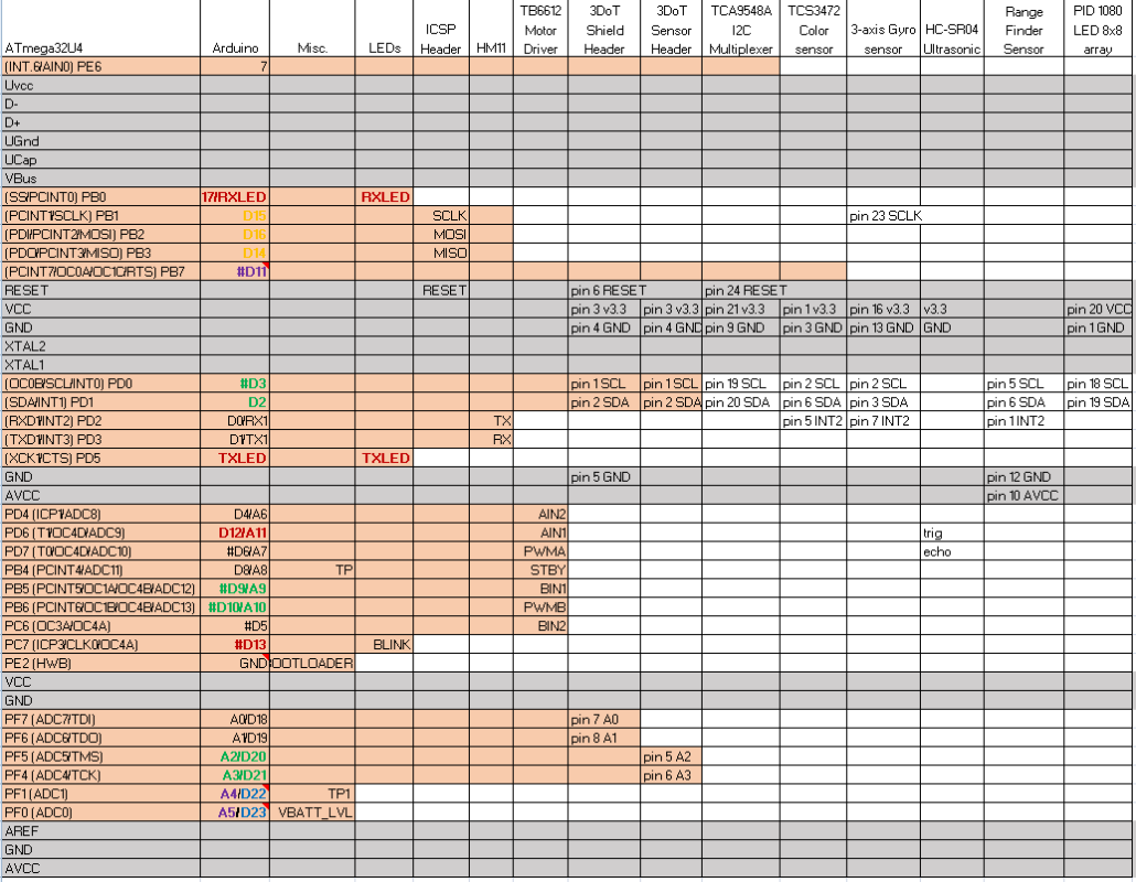
The interface matrix shows how every subsystem will be connected to the ATmega32U4 microcontroller.
Source Material
Mechanical Design
By Vanessa Enriquez (Manufacturing Engineer)
The previous group made lots of design work and ended up creating a very well designed final model. We plan on taking this exact design and only iterating on the design and adding improvements. One issue the previous group had is when they realized the speaker would not fit on the bottom panel, they decided the top panel was a better. However this, in turn, created a mess of cables running from top to bottom panels. In an attempt to organize, we will implement a cover that will contain the excess wires while still allowing the lid to open and close. This will also facilitate the disassembly of the tank. Another issue with the previous design is the lack of access to the 3Dot IO port. We plan on adding a cutout for easy recharging. The biggest change in our plan is to shrink the overall body size to accommodate the 3Dot board more snugly. This redesign requires relocating the motors and redesigning the shape of both the top and bottom panels. Lastly, the sonar wings will be removed and replaced with authenticly pleasing panels.
Source Material
Electronic and Mechanical Task Descriptions
Electronic – Trade Off Studies
By Mark Huffman (Project Manager)
By John Ocampo (Electronics and Controls Engineer)
LED Grid Display – With the LED grid display a study determining the amount of power that the grid uses when all the LEDs are on needs to be conducted. Along with the limitations of displaying images. Also, the longevity of the LEDs needs to observed by having them on for minutes at a time, then hours, and finally days (if time permits).
Color Sensor Line Detection – A case study would test the range of color detection, followed by an investigation on what would be the optimal location and configuration for the sensors for detecting lines on the floor.
Ultrasonic vs IR Distance Detection – This study would comparatively test the differences between the IR distance sensor and an easily available cheaper ultrasonic sensor.
Bridging Multiple I2C Devices – A study into how this works and how it can be used to connect multiple sensors using a minimal amount of IO connectors.
Electronic – Design Tasks
By John Ocampo (Electronics and Controls Engineer)
The current tasks I am assigned with are to determine the new parts for the Goliath. This includes implied responsibilities such as checking the I/O and power usage of the components I choose. Due to the possibility that I must choose components which use more I/O than possible I would need to design a PCB that includes an I2C extender. This PCB will also have connections to the sonar, color sensors, speaker and LED grid display. Since we have a working prototype, in the form of our predecessor’s final product I could mount(tape) components to have an approximation on how the components would function with the Goliath. More importantly, I have the ability to write, compile, and execute code over the prototype. The 1st module of code I prefer to write about is the color sensor since it seems like I do not need to use the existing work of my predecessors. The 2nd module would be to fix the tank noises the Goliath was supposed to produce.
Perform Case studies – Determine correct and effective sensors for the task
Fritzing Diagram – To Determine useable connections and wiring organization
Two Eagle Cade Schematics – For two custom PCBs containing sensors and simplifying overall wiring
Ordering of PCB’s and all required parts – Determine and locate for easier assembly
Programing – Autonomous driving, sensor feedback, driving LED display, and manual RC driving from received commands.
Manufacturing – Design Tasks
By Mark Huffman (Project Manager)
By Vanessa Enriquez (Manufacturing Engineer)
From the L1 requirements, it is evident that the previous group was unable to produce the exact scaled down model of the 302 tank. The tank was slightly larger than the previous model. As the manufacturing engineer, I plan to improve the size by rearranging the PCB positioning with respect to the motors. One attempt is to separate the motors and place one at the front of the tank and center them both. The only limiting factor should be the width of the PCB. This modification will allow us to minimize the empty space on the sides of the PCB which can improve the width. Cleaner cable routing and the addition of an access port will maintain the accessibility to the PCB for troubleshooting. Lastly, the access side panel design and sonars will be removed since the overall mission does not require these capabilities.
Case Study – Perform study on the effect of misaligned motors on driving
3D Model Redesign – Change motor placement, shrink overall size, redesign side panels and add cutouts for IO and sensors
PCB Stencil – Desgin stencil for both PCBs, order, re-flow solder and hand solder
Build Tank – 3D print and assemble tank, polish, finish surface and obtain assembly parts.
Source Material

