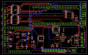
S17 Prosthetic Arm: Custom PCB Layout Design

[av_image src=’/wp-content/uploads/2017/05/PCB-Final-Layout-300×187.png’ attachment=’25420′ attachment_size=’medium’ align=’center’ styling=” hover=” link=” target=” caption=” font_size=” appearance=” overlay_opacity=’0.4′ overlay_color=’#000000′ overlay_text_color=’#ffffff’ animation=’no-animation’][/av_image]

[av_heading heading=’Spring 2017 Prosthetic Arm: Custom PCB Layout Design’ tag=’h3′ style=’blockquote classic-quote’ size=’24’ subheading_active=’subheading_below’ subheading_size=’15’ padding=’10’ color=” custom_font=”]
The Robot Company | CEO Professor Gary Hill
[/av_heading]

[av_textblock size=” font_color=” color=”]

Blog Post Created By Project Manager | Bianca Esquivel

Project Design Created by Electronics and Control Engineer | Mikael Movsisyan and Manufacturing and Design Engineer | Cedric Yannick Mbetga

[/av_textblock]

[av_heading heading=’Preliminary Information’ tag=’h1′ style=’blockquote modern-quote’ size=’20’ subheading_active=” subheading_size=’15’ padding=’10’ color=” custom_font=”][/av_heading]

[av_icon_box position=’left’ boxed=” icon=’ue864′ font=’entypo-fontello’ title=’Design Objective’ link=” linktarget=” linkelement=” font_color=” custom_title=” custom_content=” color=” custom_bg=” custom_font=” custom_border=”]
Aim: To satisfy L1.5 Custom PCB Requirement – The prosthetic arm shall implement a custom printed circuit board (PCB) that incorporates a complexity of design, implementing at least 2 layers, and includes the use surface mount components.

In compliance with with Requirement L1.7 Length – The prosthetic arm shall not exceed the length of 26 cm (User’s arm length – measured in class), the Prosthetic Limb group (following approval from Professor Hill) has decided to design and layout a single PCB board. This PCB board will host the circuit components, according to the electronic design requirements of the Prosthetic Arm and Prosthetic Hand groups. The PCB layout was done in EagleCAD.   
[/av_icon_box]

[av_icon_box position=’left’ boxed=” icon=’ue856′ font=’entypo-fontello’ title=’Materials’ link=” linktarget=” linkelement=” font_color=” custom_title=” custom_content=” color=” custom_bg=” custom_font=” custom_border=”]
Eagle CAD Software
[/av_icon_box]

[av_heading heading=’Iterations of the PCB Layout’ tag=’h1′ style=’blockquote modern-quote’ size=’20’ subheading_active=” subheading_size=’15’ padding=’10’ color=” custom_font=”][/av_heading]

[av_icon_box position=’left’ boxed=” icon=’ue8bd’ font=’entypo-fontello’ title=’First Iteration’ link=” linktarget=” linkelement=” font_color=” custom_title=” custom_content=” color=” custom_bg=” custom_font=” custom_border=”]
This Prosthetic Arm PCB consists of a LM34 analog Temperature Sensor connected to an analog pin of the Arduino Micro MCU, LT3975-1 Buck Converter, one 2-pin and four 3-pin JSTs, two terminal blocks, a 220 Ohm and a 49.9kOhm resistor, 0.47uF, 4.7uF and 22uF capacitors, a SLF7045 inductor, and a BAT54 Schottky diode.

The original trace widths were 0.3mm. The PCB additionally has a top GND plane (Red) and a bottom power plane from the 5V of the Arduino Micro MCU, as shown below.

The LT3975-1 Buck Converter IC is used to step down input voltage of 11.1V to 5V to drive the servos. The servos (hand and arm) will be connected to of the 3-pin JSTs. The other two 3-pin JSTs are used as a back-up in the case of faulty operation of the Buck during testing and mission run. The 2-pin JST is to be connected to an LED, which will be secured on the outside of the arm to notify the user when there is power supplied i.e. ON. The LM34 is connected to an analog pin of the MCU to which it provides analog readings of temperature.
[/av_icon_box]

[av_toggle_container initial=’0′ mode=’accordion’ sort=”]
[av_toggle title=’PCB Layout 1st Iteration’ tags=”]

[/av_toggle]
[av_toggle title=’GND Plane PCB Layout’ tags=”]

[/av_toggle]
[/av_toggle_container]

[av_hr class=’invisible’ height=’25’ shadow=’no-shadow’ position=’center’ custom_border=’av-border-thin’ custom_width=’50px’ custom_border_color=” custom_margin_top=’30px’ custom_margin_bottom=’30px’ icon_select=’yes’ custom_icon_color=” icon=’ue808′ font=’entypo-fontello’]

[av_icon_box position=’left’ boxed=” icon=’ue8be’ font=’entypo-fontello’ title=’Second Iteration’ link=” linktarget=” linkelement=” font_color=” custom_title=” custom_content=” color=” custom_bg=” custom_font=” custom_border=”]
In the second iteration of the pcb circuit layout protection elements were introduced, namely the 3A hold current polyfuse from the input source to the motor drivers and the 1.25A hold current polyfuse from the input source to the buck converter LT3971-5. In addition, a series of vias were added around the buck converter to act as a heat sink. Finally, a 10pF decoupling capacitor was added to the LM34 (per the datasheet layout instructions) and a 10uF decoupling capacitors were added at the source and at the input to the motor drivers.
[/av_icon_box]

[av_toggle_container initial=’0′ mode=’accordion’ sort=”]
[av_toggle title=’PCB Layout 2nd Iteration’ tags=”]

[/av_toggle]

[/av_toggle_container]

[av_hr class=’invisible’ height=’25’ shadow=’no-shadow’ position=’center’ custom_border=’av-border-thin’ custom_width=’50px’ custom_border_color=” custom_margin_top=’30px’ custom_margin_bottom=’30px’ icon_select=’yes’ custom_icon_color=” icon=’ue808′ font=’entypo-fontello’]

[av_icon_box position=’left’ boxed=” icon=’ue8bf’ font=’entypo-fontello’ title=’Third and Final Iteration’ link=” linktarget=” linkelement=” font_color=” custom_title=” custom_content=” color=” custom_bg=” custom_font=” custom_border=”]
Following recommendations from Fabian Suske and Professor Hill, additional circuit protection components were added to the final circuit schematic, namely polyfuses and decoupling capacitors at the input source and to both IC inputs. The schematic above shows the schematic of the Prosthetic Arm group only.

Below is the link to the Prosthetic Limb (Arm + Hand PCB)

https://drive.google.com/open?id=0B6kkqAMmUffraGpHX0t5Mno0YnM
[/av_icon_box]

[av_toggle_container initial=’0′ mode=’accordion’ sort=”]
[av_toggle title=’Final PCB Circuit Schematic’ tags=”]

[/av_toggle]
[av_toggle title=’Final PCB Layout’ tags=”]

[/av_toggle]
[/av_toggle_container]

[av_hr class=’default’ height=’50’ shadow=’no-shadow’ position=’center’ custom_border=’av-border-thin’ custom_width=’50px’ custom_border_color=” custom_margin_top=’30px’ custom_margin_bottom=’30px’ icon_select=’yes’ custom_icon_color=” icon=’ue808′]