
Spring 2017 Prosthetic Hand: Solidworks Palm Design
The Robot Company | CEO Professor Gary Hill
Blog Post Created by Project Manager | Bianca Esquivel
Project Designs Created by Manufacturing and Design Engineer | David Mendoza
Table of Contents
Introduction
When starting this project, it was decided to design a different hand, from previous generation hands design. This was mostly because we found a volunteer, Ernesto, to help demo the project and so the hand need to match the same size as the other hand. This will go over the process of designing and re-designing the palm, and any other parts need to be attached to the palm.
This process is performed in response to requirement:
L1-9 Appearance: The prosthetic hand shall be approximately the same size as the customer’s other hand.
Palm: 11 cm
L2-7 Appearance | System
The prosthetic hand should have a humanoid design such that most integrated parts will not be visible, corresponding to the customer’s measurements: Index Length: 9 cm, Middle Length: 10 cm, Ring Length: 8 cm, Pinky Length: 7 cm, Thumb Length: 10 cm, and Palm Length: 11 cm
Process
The prosthetic palm was going to be modeled after the Inmoov design (Langevin) as shown in Figure 1. The palm would have been made up of two or three parts, depending on how it would have been designed in Solidworks. The original idea was to combine the two parts that connect to the ring and pink finger to make it into two-part palm.
Once we found a new customer, Ernesto, we had to change the design from putting the servo and/or motors from the lower part of the wrist to being inside the palm. Then from the thesis of Hussein on page 26 I modeled the palm to be like his. With the help of auto trace in Solidworks, I took the picture shown in figure 2, and traced it to design the new palm. To fit the size of Ernesto I made the length, from the fingers to the wrist, to be 11 cm and then width was about 90 cm, which turned out to be too big. The fingers would fit on the palm and use some screws or pins to lock them into position. Than the string will go through the holes into the palm and connect to the spools, which are connected to the DC 12 V 10 RPM motors and turn to pull the string, and bend the fingers. When I printed out the palm I had designed, there were some issues as to how the motors and servo would be placed and how they would stay in one position.
After trying to design the palm from scratch I looked back at the tact hand (2016) and saw how they could keep the motors in place. So, I began to redesign that part so that they would fit our finger sizes, that is shown in figure 3.
After designing this part, I looked at how the servo will be held in place, this part was also modeled from a prat on the Tact hand (2016). So, I redesigned the cover for the servo, as it is shown in figure 4, and it will be screwed on inside the palm with half the servo sticking out so it can connect to the thumb and move freely.
Then after looking over the designs I made for the palm, both the Project Manager, Bianca Esquivel, and I decided to make some changes, to how the DC motors will be placed and how the fingers will connect to the palm. Now the holes that will connect the fingers to the palm will be circular holes for the string to go through to reach the DC motors. I also added in an extra space for the servo to be screwed on, for the thumb. After talking with the arm group, about how we are to connect the hand and arm together. We decided that the arm will go inside the palm that will have to holes to put screws through and hold them together.
The final part was the cover for the palm. Which I traced the outer lines of the palm, then I will screw nails to hold the cover onto the palm.
Results
When the palm from figure 5 was finally printed, and assembled together with the fingers, it was seen that the hand would not be able to work or grasp anything. This could be because the fingers were not placed in the right position or that they were too long. Another error that occurred with this design was that there was no place to hold the motors still, so that they can pull the strings.
Conclusion
It would have been best to print out the palm sooner and faster, to be able to look over it and see what need to be fixed and possible ways to fix it. It was tough trying to figure it out all at once on Solidworks, the best approach would be to design it and print it out then talk to the team about how to make it better. It would have helped a lot more, to print out the hand sooner and then try and solve possible ways to use the pulley system for the fingers and how to hold the motors in place.
Link to Palm Solidworks Files:
Figure 1

Figure 2
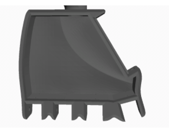
Figure 3

Figure 4

Figure 5

Figure 6

References
Langevin, G. (n.d.). Hand and Forarm. Retrieved April 30, 2017, from http://inmoov.fr/hand-and-forarm/
Hussein, M. E. (2014). 3D Printed Myoelectric Prosthetic Arm (Unpublished master’s thesis). Sydney University. Retrieved from https://drive.google.com/folderview?i…
S, P. (2016, May 12). Tact: Low-cost, Advanced Prosthetic Hand. Retrieved April 30, 2017, from http://www.instructables.com/id/Tact-Low-cost-Advanced-Prosthetic-Hand/