Spring 2017 Prosthetic Hand: Xbee Communication Test
The Robot Company | CEO Professor Gary Hill
Blog Post created by Project Manager | Bianca Esquivel
Project Test Executed by Electronics and Control Engineer | Forest Nutter
Table of Contents
Preliminary Information
Test Objective
We need to verify the hook up of the Xbee so we can design a shield for it. We want the Xbee to be able to send and receive data from a wireless source. Ex hand to foot and vice versa. We need to know what pins we need in order for the Xbee to work like Rx, Tx, CTS, RTS. we also need to research level shifting since the Xbee is a 3.3v device and see if the arduino 3.3v regulator is strong enough for the Xbee.
This Test Reflects the Subsystem Requirements:
L2-6 Software | System
The hand will be coded so that two individual fingers can move independently and remotely.
Subsystem:
L2-6.1 The hand shall be controlled via an Arduino Nano, and thus will be coded using the Arduino IDE.
L2-6.1.2 The Arduino IDE should contain a Xbee coded section so that it will connect to the flex sensors on the toes.
Materials
(1) Arduino Uno
(1) Arduino Nano
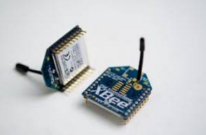
(2) Xbees
(2) Xbee Explorers
Test Set Up
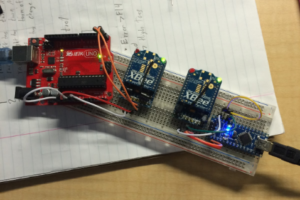
One Xbee is connected to the Arduino Uno and the other is connected to the Arduino Nano and from this set up, we can test (a) whether the Xbees can send and receive data and (b) that their communication is bi-directional.
Arduino Code
Arduino Code:
void XbeeSR(int Mode, int PWN, int &FR1, int &FR2, int &FR3){
while (Serial.available()>0 && incomingByte != 254) { //run until you find the SYNC char or the serial buffer is empty.
if (incomingByte==254){
FR1=Serial.parseInt();
FR3=Serial.parseInt();
//while (Serial.available()>0){
//}
}
Serial.println(Mode);
}
Results
Verified that Communication is possible. (Software)
Verified that bi-directional communication is possible without flow control. (Software)
Verified that Communication is possible. (Arduino)
Verified that bi-directional communication is possible without flow control. (Arduino)
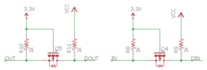
Found a level shifter schematic online that will change 5v to 3.3v and 3.3v to 5v. We found it from the sparkfun Xbee explorer shield.
Xbee Communication: Send & Receive
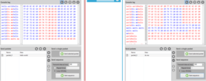
Xbee communication is visible here through the software, specifically X CTU software which is a free, multi-platform application that is best used for simple wireless network configurations. Here, we verify that the Xbee is hooked up correctly and can send and receive data. In this picture we send ‘hello world’ from one Xbee to the other one.
Xbee Communication: Bi-Directional Application
3.3 V Regulator
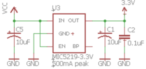
The output of the arduino micro 3.3v regulator is max 50 mA but we have been warned that the board may overheat at this current. That is why almost every Xbee shield has a 3.3v regulator.
Xbees typical current draw is 50 mA for idle/receiving. So we decided to use a 3.3v regulator just to be safe and make sure it is reliable. We found this from the sparkfun Xbee explorer shield.
Conclusion
The Xbee is hooked up correctly in the schematic and does not require (CTS, RTS) pins. This means that the Xbee can send and receive data with only 2 pins hooked to the Arduino instead of 4. This is useful for us because we were low on usable pins and this helps us conserve pins for other uses. Using the Xbee we send data from the foot’s flex sensors in the form of its various modes to the hand and receive data from the hand’s force sensors so that the vibrating motors in the foot can reference that feedback. We are using pieces from the sparkfun Xbee explorer shield, such as the level shifter and 3.3v regulator, to make sure that data from the Arduino to the Xbee does not damage the Xbee, and that the Arduino does not overheat because of too much current draw from the Xbee.
For future reference, the software used to code the Xbee XTCU is free for download and can be downloaded with through this link:

