Spring 2016 3DOT Goliath, Progression of Laser Tag components
By: Kevin Moran (Electronics and Control Engineer)
In this post we will explore the progression in the components explored throughout this project to make the Laser Tag game possible.
- My first idea was to use a laser diode as the emitter and a Photo-resistor as the receiver.
- Pros:
- 15 meter range
- No Assembly required
- Pros:
- Power dissipation of 75mW
- Cons:
- Dangerous to the human eye
- No circuit to build and learn from
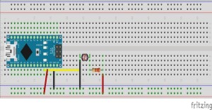
Simplistic Laser Receiver build with Fritzing diagrams (Photo-resistor)
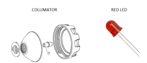
- Since we are designing a 3DoT Rover that will be manufactured for children, the laser was discarded. My next idea was to use a simple LED alongside a collimator to simulate a safer laser beam.
- Pros:
- Safe to use
- 3 feet range
- Pros:
- Power dissipation of 60mW
- Cons:
- Beam had a 3 inch diameter from 3 feet distance
- Did not meet the “cool” requirement
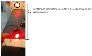
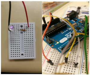
Red LED with collimator powered by a 4.5V power supply and 220ohm resistor
- The third option to be able to satisfy our requirements for the laser tag game was to use a Photo-transistor as a receiver alongside an IR LED as the emitter
- Pros:
- Safe to use
- Will require PCB board to cancel our noise and filter signal
- Pros:
- Analog voltage output can be manipulated
- Cons:
- Output contains noise.
- Range has to be worked on
- Not visible to naked eye
Although the range is not as impressive as the laser, this is a safe device to use, as Infrared Light is not absorbed by the human eye. By using this device I will be able to satisfy the rubric for the PCB schematic design, as I will be adding on a Schmitt Trigger, which will be discussed in the following blog post.
Emmiter/ Receiver
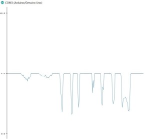
Voltage output using Arduino Analog Pins
This circuit still needs to be filtered out and passed through an Inverting Schmitt Trigger. The Schmitt trigger will filtered out the noise and using voltage resistors there will be two voltage thresholds. Which will then be digitized and sent to the microcontroller for processing.

