Spring 2016 A-TeChToP Central Sensor Suite Sensor Post #2
By: Stephen Cortez (Electronics Engineer)
Introduction
This blog post will cover the remaining two sensors that were made by the group, which includes the ECG and blood oximeter. Research concluded that commercial devices for these categories were either too large or too expensive to implement into the project, requiring custom sensors.
The ECG is a series of IC components along with resistors and capacitors that form analog filters that take the raw biological signals from a subject in order to produce a clear heart signal. Then, the blood oximeter uses a red LED, an infrared (IR) LED, and the TSL235R sensor to measure the percentage of oxygen within a subject’s blood based upon how much red light is absorbed by oxygenated blood while IR light is simultaneously passed through the same section of skin.
Table of Contents
ECG
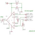
For the ECG, this link will show the circuit that was used as a template for the CSS’s circuit: https://www.youtube.com/watch?v=Uj9OXNg_p78 [1]. Looking at the schematic, it is clear that the circuit uses an instrumentation amplifier, an operational amplifier, a highpass filter, and a lowpass filter. The instrumentation amplifier used by the group was an INA128, the respective pin connections were not changed from the template circuit. Next, the highpass filter in the template was changed to be made using a 1uF capacitor and a 1Mohm resistor, creating a cutoff frequency of about 0.16Hz. This adjustment was made to reduce the amount of relevant ECG signal was noticed to be being removed by the original filter and simply preserve the signal while eliminating baseline noise. Next the lowpass filter was implemented, using 4.3Mohm resistor and a 1000pF capacitor, along with the operational amplifier. The lowpass new cutoff frequency of about 36Hz was adjusted in order to remove more muscle artifact noise from the ECG signal considering that there was still noticeable disruptions from signals below 50Hz. However, since 50Hz is a characteristic frequency of muscle artifact noise, a notch filter was added to the circuit designed to remove 50Hz signals. The final output from the notch filter was then fed into an analog pin on an Arduino Uno. Using a simple analog read sketch, the ECG signal could be viewed in real-time of the Serial Plotter Arduino IDE tool. In order to use the Serial Plotter, which is a fast and easy alternative to an oscilloscope should the situation be appropriate, you must have Arduino Ide version 1.6 at least. Newer versions will have it as well. This tool functions just like the Serial Monitor in that the Baud rates between the sketch and the monitor must match, but a plot can be seen instead of values. The following image is a snippet of the final ECG circuit design used in the CSS project.

Fig 1.
Looking at this figure, there are three leads that enter the instrumentation amplifier: Left Arm, Right Arm, and Ref-GND. These three leads symbolize the Einthoven Triangle electrode formation, which was selected in order to minimize the number of electrodes while still promoting a quality signal. The Left Arm, connected to INA128 pin 3, is the positive electrode which will be placed on the bottom left abdomen of the subject. The Right Arm, connected to INA128 pin 2, is the negative electrode and will be placed on the upper right pectoralis of the subject. Finally, the Ref-GND lead, which is connected to Vref, is the reference ground connection. This connection is necessary for the INA128 to operate since it provides a bottom voltage reference point for the IC and creates the energy potential needed for the component to operate. Once these leads are properly connected using good electrodes, the circuit should provide a clear ECG signal on the Serial Plotter tool, where the P, QRS, and T waves/complex will be identifiable.
Blood Oximeter
Next, the blood oximeter was slightly more complex to develop. Taking into account the principles behind blood in relation to absorption of the electromagnetic spectrum, which can be found here: http://portal.fke.utm.my/fkelibrary/files/mohammadjabbarbinhusin/2012/9_MOHAMMADJABBARBINHUSIN2012.pdf [2], the oximeter was designed around the fact that the TSL235R is capable of converting light information into frequencies, but only through digital means. Thus, this sensor required for the group to use timers and interrupts in the Arduino IDE software in order to count the pulses of the frequencies outputted by the sensor and converting them into relevant information. The final code used for these purposes will be provided in other links, but will be explained here. Initially, timers are difficult to implement but can become quite useful. Using the function “millis();”, a timer will begin at that exact moment in the code. Thus, variables of the type “unsigned long” are able to be assigned as timers, meaning that they hold the timer value whenever “millis()” is used and can be incremented or reset depending on the needed operation of the code. Using the line “unsigned long Start = millis();” will record that start of a timer at the particular section of the code. Once millis() is first called upon, then all subsequent calls will be later time values in the code each time the void loop is run. This means that at the end of each void loop iteration, the timer value will reset. However, this does not mean that the total time that you have been running your code is lost, since the unsigned long value at the end of each loop can be set equal to the timer and then added with itself, thus incrementing the time and keeping track of the total time that your code has been running. It is important to note that timers are necessary for reading frequency digital outputs from sensors since measuring periods must be made in order to know how long a sampling time should be made. In the oximeter code, a measurement period of 1 second is used, in which, an interrupt is attached to the digital pin reading the TSL235R sensor.
Using a “while” loop, the current time of the running code can be incremented for each time that the criteria of whether the current time minus the starting time is greater than or equal to 1 second has been met. Within the while loop, for each time this criterion is not met, the attached interrupt will quickly increment a counter to represent the number of pulses counted as well as sum the current time with itself in order to increase. However, notice that this particular interrupt has been made to only trigger when the rising edge of a waveform is detected, meaning that only when the TSL235R senses a wavelength and outputs a rising edge, the pulse will be counted. When the criterion is finally met the code will exit the while loop, make calculations based upon the number of pulses counted, and output the frequency detected during the sampling interval as well as reset the timer variables. This method of digital measurement has proven to be quite effective and other useful features can be carefully placed throughout the code in order to improve the overall performance and functionality. The following link is a forum that helps describe these measurements and even provide some examples: http://forum.arduino.cc/index.php?topic=21536.15 [3]. For the CSS project, a 1 second measurement was taken while only the IR LED was on and another when the Red LED and IR LED were both on. The calculated ratio between these measurements were used to create a percentage value related to the relative percentage of oxygen present within a subject’s blood. Healthy values should be expected to be about 95 to 99 %, but most likely not 100% since that is not possible. With these calculations, a relative blood oxygen percent can be calculated.
References
[1] – J.Dominguez.(2013).ECG Circuit Class Project.[Online].Available: https://www.youtube.com/watch?v=Uj9OXNg_p78
[2] – Husin, M. J. B.(2012).Multipurpose Pulse Oximeter.[Online].Available: http://portal.fke.utm.my/fkelibrary/files/mohammadjabbarbinhusin/2012/9_MOHAMMADJABBARBINHUSIN2012.pdf
[3] – Arduino.(2010).How to: Light to Frequency Converter – TSL235R?.[Online].Available: http://forum.arduino.cc/index.php?topic=21536.15