Spring 2016 A-TechTop Seizure Watch Subgroup Solution for Decreasing Size
By Marena William (Manufacturing Engineer)
Introduction
After the group was debriefed on the Critical Design Review (CDR), we realized that our housing dimensions (maximum dimensions) need to be changed. Throughout the course of the semester our goal was to have a fully functional seizure watch however after the PCB layout was done this goal seemed unachievable. This post discusses how we approached this problem.
Table of Contents
New PCB layout/ Flex PCB
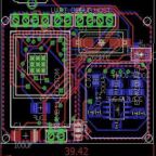
The PCB that you see in our previous post has dimensions of 38.10×59.06 mm. Most of the PCB area is occupied by the SAMB11, the EDA connector and the 24 Pin connector which result in a large PCB compared to an average watch. A good approach to this problem is designing a flex PCB that allows the board to have more area looping around the wrist instead of being limited to one side of the wrist. Due to time constrain and the available sources this solution was not implemented this semester however a possible design is provided (figure 1), also see notes.
Another creative solution could be dissecting the SAMB11 into its components and then laying out this components separately which allows more flexibility in the design.

Figure 1: Possible condensed PCB design with less headers.
Notes
- The new dimensions of the PCB does not take in consideration the battery holder as it could be attached separately from the PCB in a more sophisticated design.
- Eagle Cad does not support flex PCBs this design was done for illustration purposes.
- The same notes for the previous PCB was followed for this design.
Conclusion/ Next Task
As a result of the above work the SolidWorks design need to be modified to reflect the changes. The modified model should now be a display model of what the watch could look like given more time and resources.