Spring 2016 AdBot System Block Diagram and Interface Matrix Definition
By Don T. (Mission, Systems, and Test)
Dang Le (Project Manager)
A system block diagram and interface matrix allow people to replicate the project. They show the components that are used and wire connections. AdBot’s interface matrix begins displaying all the Arduino Uno’s pins and names. Components are placed in columns. When an Arduino pin is not vacant anymore, the row turns white to indicate that the next component cannot place a jumper lead in the white box.

Figure 1 Interface Matrix Definition
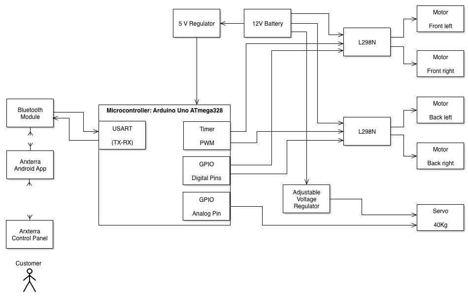
Figure 2 System Block Diagram
Resource Files
Link 1 AdBot Interface Matrix Definition Excel Sheet
The system block diagram is created using the full version of Shapes.