Spring 2016 Pathfinder Charging Control Circuit
by: Tuong Vu (Sensors, Actuators and Power)
Table of Contents
Introduction:
This document is to explain the charging control circuit of the pathfinder. The customer wants the pathfinder to have a self-charge capability. This circuit will help regulate voltage and circuit during the charging time of the batteries by the solar panel. The purpose is to prevent the damage to the batteries from overcharging.
Electronic Components:
- 2 X resistors 1k ¼ watts
- solar panel : NPower Amorphous Solar Panel Battery Maintainer Kit – 2.5 Watts
- 2 X batteries : 10000MAh lead Battery
- N- channel IRF840
Understand Components:
Figure 1
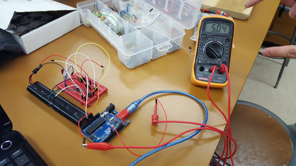
According to the diagram above, two pins are reserved for this circuit from the Arduino, specifically one analog pin and the other digital pin. Analog pin is used for the intake voltage data from the voltage divider. We implement the voltage divider to prevent damaging the I/O pins on the arduino, see table 1. Ideally the mosfet acts like switch such when voltage into the gate is much higher than the threshold voltage, the mosfet turns on, which means the drain and source pins are in series together. Arduino can generate a 5 volts output, which is enough to turn the mosfet on. When the drain and source are connected the solar panel is directly in series with the battery, allowing the current to flow and effectively charging the battery.
The batteries and the solar panel switch place
Arduino Code:
Code generates a sequence of addition of input voltage taken from the voltage divider, which will go through an if statement in order to turn the Mosfet on.
/*————————————————————–
Program: Volt_measure
Description: Reads value on analog input A2 and calculates
The voltage assuming that a voltage divider
Network on the pin divides by 11.
Hardware: Arduino Uno with voltage divider on A2.
Software: Developed using Arduino 1.0.5 software
Should be compatible with Arduino 1.0 +
Date: 22 May 2013
Author: W.A. Smith, http://startingelectronics.org
————————————————————–*
// number of analog samples to take per reading
#define NUM_SAMPLES 10
int sum = 0; // sum of samples taken
unsigned char sample_count = 0; // current sample number
float voltage = 0.0; // calculated voltage
int r8 = 8;
void setup()
{
Serial.begin(9600);
pinMode(r8,OUTPUT); // output pin.
}
void loop()
{
// take a number of analog samples and add them up
while (sample_count < NUM_SAMPLES)
{
sum += analogRead(A0);
sample_count++;
delay(10);
}
// calculate the voltage
// use 5.0 for a 5.0V ADC reference voltage
// 5.015V is the calibrated reference voltage
voltage = ((float)sum / (float)NUM_SAMPLES * 5.015) / 1024.0;
// send voltage for display on Serial Monitor
// voltage multiplied by 11 when using voltage divider that
// divides by 11. 11.132 is the calibrated voltage divider
// value
Serial.print(voltage * 11.132);
Serial.println (” V”);
sample_count = 0;
sum = 0;
if (voltage < 4)
{
digitalWrite(r8,HIGH);
//delay(5000);
}
else if ( voltage > 4)
{
digitalWrite (r8,LOW);
//delay(5000);
}
}
//delay(100000) .
This code was written by W.A. Smith, but is modified with the if statement by us. The Arduino is taking samples and applying them through the equation in the code ( see code) thus gives the voltage increment we need. The output voltage generated by the arduino is the 8 digital pin, this is where the mosfet going to get the voltage to turn on or off.
figure 2 ATmega 328P specifications
Test results
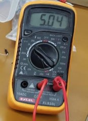
The above picture shows that the battery has 5.04 V before charging
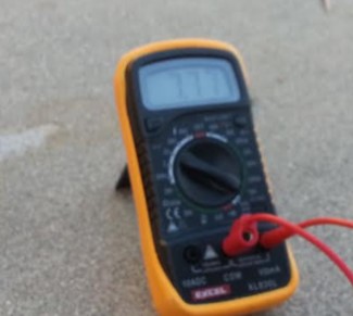
This picture shows that the battery now has 7.77 V after charging
Source Materials:
Arduino: Read Analog Voltage click here
NASA: How do Photovoltaics Work? click here


