Spring 2016 Velociraptor: Circuit Schematic & Servo Load Test
By: Ashlee Chang (E&C)
Table of Contents
A Clean Electronic Setup
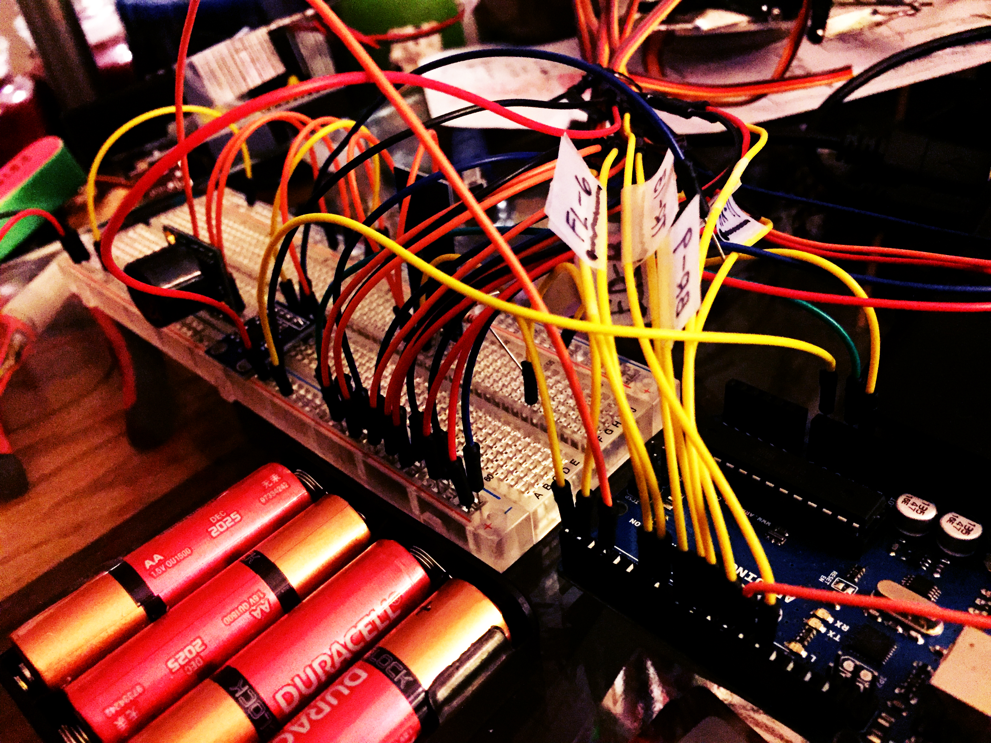
Breadboard testing
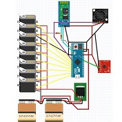
The electronics journey goes as so: Fritzing diagram, breadboard testing, circuit schematic, and then PCB (printed circuit board) fabrication. All electronic components are Arduino microcontroller, four batteries, eight servos, Bluetooth, ultrasonic sensor, and accelerometer. Notably, there are quite a bit of components, meaning a lot of wires needed to interface between them all. That is why the team decided that most of the wiring would be implemented on the PCB to avoid a messy project. Also, the microcontroller will be mounted directly on the PCB for this very purpose.
Servo Load Test
Servos in general draw quite a sum of current, and that current draw is proportional to the load (weight) the arm has to push against. A voltage regulator will be needed for the velociraptor, so it’s essential to see approximately how much current is drawn by these powerful servos so an appropriate regulator can be chosen. A test was conducted to see the servo load versus current draw.
Servo load and current test
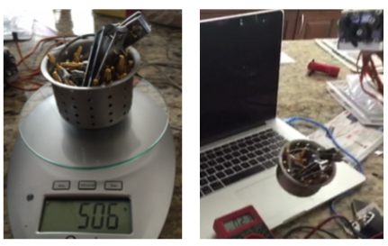
A bucket containing miscellaneous materials to reach a particular weight was used and weighed on a scale. Afterwards, a string was used on the bucket and attached to the servo. A simple sweep code was installed on the servo to work against this load. An ammeter was inserted into the servo and power source loop.
Servo load and current results
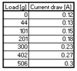
The results were documented in the above table. The velociraptor currently weighs 544g (not taking into account the PCB, microcontroller, sensors, and Bluetooth). Thus, the project will weigh around a total 570g-600g. Taking the current draw of 0.3A at 506g from the table, this brings the current draw of eight servos at 2.4A. If the project is estimated to be 600g, the total current draw should be close to 3A, not taking into account current going to other parts of the circuit. Thus, the voltage regulator must be capable of handling over 3A.
Voltage Regulator
The voltage regulator is the only major component on the circuit schematic. Choosing a proper one was difficult. A decision between an LDO (low dropout voltage) voltage regulator versus switching regulator was contemplated. The switching regulator is actually highly efficient compared to the LDO voltage regulator. The lesser the inefficiencies, the lower amount of energy will be wasted as heat. Because the velociraptor shall be designed as a child’s toy, hot electrical pieces is a definite no-no that must be avoided for the health and safety of the user. With all switching regulators, there needs an inductor in the suggested schematic, which requires specific placement of the schematic in terms of distance on the PCB. Finding a switching regulator with an internal inductor proved to be impossible. In addition, there are not many switching regulators capable of stepping down small voltages. In the velociraptor’s case, the voltage had to be stepped down from 7.4V to 6.0V, which is only a change of 1.4V. Due to the complexity of switching regulators, the team decided on an LDO voltage regulator.
Some spec considerations that must be taken into account were: 5A maximum current output, input of 7.4V, output of 6V, capable of stepping down 1.4V, efficient, and through-hole (the smaller the package size, the hotter the component can get). The voltage regulator agreed on was MIC29512. Some additional features include current limiting protection, thermal shutdown, and an enable input pin that can be used to turn off the voltage regulator when not in use.
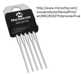
MIC29512 Voltage Regulator
Heat Sink
If the voltage regulator were to be a surface mounted piece, some copper embedding must be implemented. However, seeing the voltage regulator is a through-hole TO-220 package, a screw on heat sink can be used. For calculations based on the datasheet, the math is as follows: Rtsa = [125 – 50] C / 3W – 2 C/W – 1 C/W = 22 C/W. Any heat sink under 20 C/W would be ideal, but one with a specification of 9.6 C/W was chosen because, after all, this is a child’s toy.
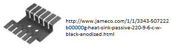
Heat sink choice
Eagle Circuit Schematic
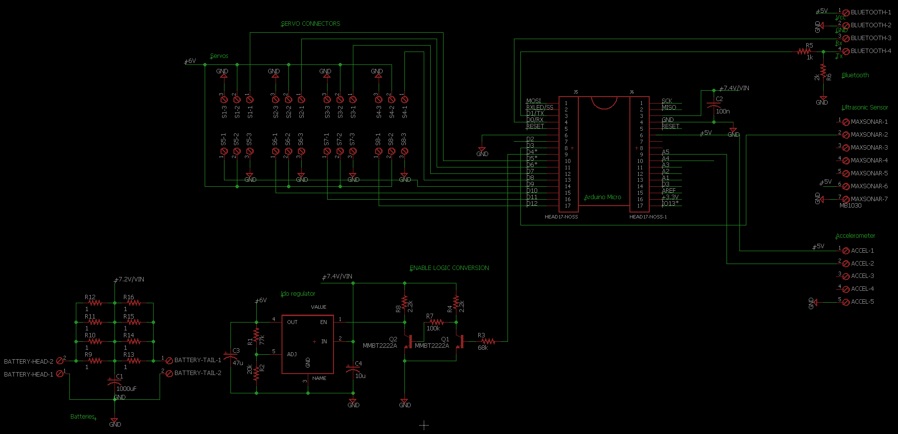
Velociraptor circuit schematic
The final circuit schematic is shown above. Both two batteries will be in series, and those two are in parallel. The resistors in between are used to help with any possible offset in between the two battery pairs. Transistors were placed to use the enable pin. A large capacitor needs to be next to the batteries. A TO-220 package was made for the schematic, and the recommended schematic was constructed based on the MIC29512 datasheet. The respective resistors used were calculated to output 6V on the voltage regulator. The batteries were connected to both the microcontroller (which can take inputs up to 12V) and the voltage regulator. The regulator feeds the servos as to get to that optimal voltage of 6V. The Arduino micro is placed directly in the schematic. Lastly, some simple connectors were used for the sensors, actuators, and Bluetooth.